1991 FORD FESTIVA ECO mode
[x] Cancel search: ECO modePage 5 of 454

TURBO BOOST GAUGE & SENSOR (CAPRI)
1. Disconnect 3-pin boost sensor electrical connected located on right side of firewall. Turn ignition on. Measure voltage between
Yellow/Green and Black wires. Voltage should be greater than 10 volts. Turn ignition off. If voltage is greater than 10 volts, go t o n e xt
step. If voltage is 10 volts or less, repair Yellow/Green or Black wires as necessary.
2. Remove instrument panel. See INSTRUMENT PANEL
under REMOVAL & INSTALLATION. Disconnect instrument panel 8-pin
connector. With boost sensor disconnected, measure resistance through White/Black between instrument panel and boost sensor harness
connector. If resistance is less than 5 ohms, go to next step. If resistance is 5 ohms or more, repair or replace White/Black wire.
3. With 8-pin instrument panel connector disconnected, ground White/Black at boost gauge. Boost gauge should read low. Apply 12 vo l t s
to White/Black wire at boost gauge. Boost gauge should read high. If boost gauge operates as specified, go to next step. If boost gauge
does not operate as specified, replace boost gauge.
4. Reconnect instrument panel connectors (if removed). With ignition on and boost sensor disconnected, install jumper wire between
Yellow/Green and White/Black wires of boost sensor vehicle harness connector. Boost gauge should read high. If boost gauge reads
high, replace boost sensor. If boost gauge does not read high, go to TROUBLE SHOOTING
for other possible causes.
REMOVAL & INSTALLATION
INSTRUMENT PANEL
Removal & Installation (Capri)
1. Disconnect negative battery cable. Pull storage compartment from heater/radio bezel. Pull outward and remove trim covers located on
both sides of steering column. Remove retaining screws and carefully pull instrument panel bezel partially away from dash. Disconnect
electrical connectors from clock and switches in bezel. Remove instrument panel bezel.
2. Disconnect speedometer cable from transaxle. Remove instrument panel retaining screws and slide instrument panel outward. Press lock
tab and release speedometer cable from instrument panel. Remove electrical connectors from rear of instrument panel. Remove
instrument panel. To install instrument panel, reverse removal procedure.
Removal & Installation (Festiva)
1. Disconnect negative battery cable. Remove upper and lower steering column covers. Remove screws from panel bezel and remove bezel.
Disconnect rear wiper switch and rear defogger switch wiring harness connectors (if equipped).
2. Remove instrument panel-to-dash screws. Pull panel from dash. Reach behind panel and release speedometer drive cable lock tab. Lift
lock tabs and disconnect 2 electrical connectors from rear of panel. Remove panel. To install instrument panel, reverse removal
procedure.
INDICATOR LIGHTS
Removal & Installation
Remove instrument panel for access to indicator light bulbs. See INSTRUMENT PANEL under REMOVAL & INSTALLATION. To remove
bulb, rotate bulb counterclockwise to disengage locking tabs. When tabs release, pull bulb from printed circuit board. To install bulb, reverse
removal procedure. Install instrument panel and test lights.
SPEEDOMETER R & I
Removal & Installation (Capri)
R e mo ve n e ga t ive b a t t e r y c a b l e . R e mo ve in st r u me n t p a n e l . S e e INSTRUMENT PANEL under REMOVAL & INSTALLATION. Disassemble
instrument panel and remove speedometer/tachometer/boost gauge assembly from instrument panel. To install, apply a 3/16" (4.6 mm) b al l o f
Silicone Damping Grease (D7AZ-19A331-A) into drive hole of speedometer head. Reverse removal procedure to complete installation.
Removal & Installation (Festiva)
R e mo ve n e ga t ive b a t t e r y c a b l e . R e mo ve in st r u me n t p a n e l . S e e INSTRUMENT PANEL under REMOVAL & INSTALLATION. Disassemble
instrument panel and remove speedometer head assembly from instrument panel. Speedometer is a separate module and can be removed
independently from gauges. To install, reverse removal procedure.
SPEED SENSOR
On vehicles equipped with speed control, a speed sensor is mounted in speedometer head assembly. If replacement is necessary, speedometer
head assembly must be replaced. See SPEEDOMETER R & I
under REMOVAL & INSTALLATION.
FUEL GAUGE
Removal & Installation
Remo ve in st ru men t p an el . See INSTRUMENT PANEL under REMOVAL & INSTALLATION. Disassemble panel and remove fuel gauge.
To install gauge, reverse removal procedure. On Capri, the fuel/volt gauge must be replaced as an assembly.
FUEL SENDING UNIT
Removal & Installation
1. For Festiva, remove rear seat. For Capri, remove rear seat cushion. On Festiva, remove carpet hold-down pins and lift carpet for access
to sending unit access plate. On all models, remove access plate screws. NOTE:Federal law requires that a label stating the odom eter has been repaired or replaced be affixed to any
vehicle that has its odom eter repaired, replaced or set to zero.
Page 4 of 5 MITCHELL 1 ARTICLE - INSTRUMENT PANEL 1991 ACCESSORIES & SAFETY EQUIPMENT Ford Motor Co. Switches
...
3/10/2009 http://www.eautorepair.net/app/PrintItems.asp?S0=2097152&S1=0&SG=%7B959286D2%2D3A85%2D4BFC%2D9C5C%2D
...
Page 191 of 454

Back To Article
E - T HEORY/OPERAT ION
1991 ENGINE PERFORMANCE Ford/Mercury T heory & Operation
INTRODUCTION
This article covers basic description and operation of engine performance-related systems and components. Read this article before attempting
to diagnose systems with which you are not completely familiar.
COMPUTERIZED ENGINE CONTROLS
An electronic Control Assembly (ECA) receives and processes signals from various sensors and switches. See Fig. 1 . It then generates signals
which control ignition timing, fuel injection functions and various emission control devices. The ECA has system diagnostic capabilities and
will store trouble codes for use by service technicians.
Fig. 1: Identifying Input Devices & Output Signals (Not All Shown)
Courtesy of FORD MOTOR CO.
ELECTRONIC CONTROL ASSEMBLY (ECA)
The ECA is located under the instrument panel on the driver side. It receives and processes data from sensors, switches and other components.
The ECA generates output signals to control fuel injection, spark timing, other engine functions and emission systems.
CEC INPUT DEVICES
Vehicles are equipped with different combinations of input devices. Not all devices are used on all models. To determine input device usage of
a specific model, see appropriate wiring diagram in WIRING DIAGRAMS article. The available input devices include the following:
BAROMETRIC PRESSURE SENSOR (BP)
This device senses changes in barometric pressure. The ECA uses this information in calculating fuel metering, ignition timing and idle speed.
On Festiva, BP is incorporated into the ECA. On Capri, BP is located on the passenger-side cowl.
BRAKE ON-OFF (BOO) SWITCH
This switch, located at the brake pedal, senses brake operation. The ECA uses this information in calculating fuel metering.
NOTE:Com ponents are grouped into 2 categories. T he first category is CEC INPUT DEVICES, which control or
produce voltage signals m onitored by the control unit. T he second category is CEC OUT PUT SIGNALS,
which are com ponents controlled by the control unit.
Page 1 of 6 MITCHELL 1 ARTICLE - E - THEORY/OPERATION 1991 ENGINE PERFORMANCE Ford/Mercury Theory & Operation
3/10/2009 http://www.eautorepair.net/app/PrintItems.asp?S0=2097152&S1=0&SG=%7B7DD6473C%2DB5BB%2D4F20%2D9D70%2D
...
Page 263 of 454
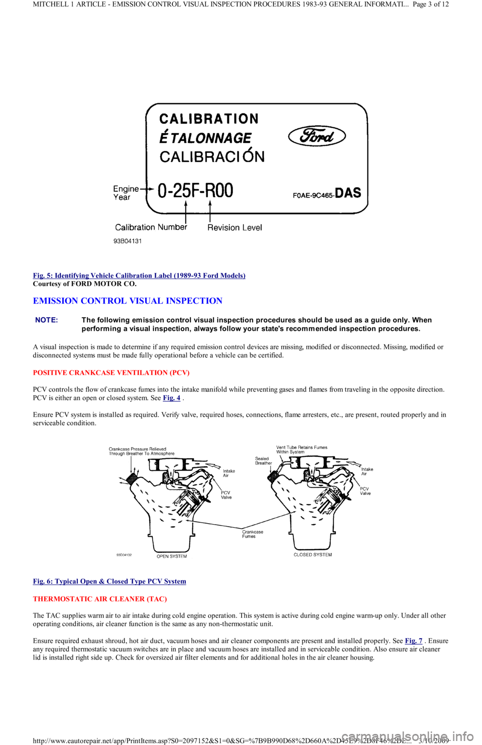
Fig. 5: Identifying Vehicle Calibration Label (1989
-93 Ford Models)
Courtesy of FORD MOTOR CO.
EMISSION CONTROL VISUAL INSPECTION
A visual inspection is made to determine if any required emission control devices are missing, modified or disconnected. Missing, mo d ifie d o r
disconnected systems must be made fully operational before a vehicle can be certified.
POSITIVE CRANKCASE VENTILATION (PCV)
PCV controls the flow of crankcase fumes into the intake manifold while preventing gases and flames from traveling in the opposite direction.
PCV is either an open or closed system. See Fig. 4
.
Ensure PCV system is installed as required. Verify valve, required hoses, connections, flame arresters, etc., are present, routed properly and in
serviceable condition.
Fig. 6: Typical Open & Closed Type PCV System
THERMOSTATIC AIR CLEANER (TAC)
The TAC supplies warm air to air intake during cold engine operation. This system is active during cold engine warm-up only. Under all other
operating conditions, air cleaner function is the same as any non-thermostatic unit.
Ensure required exhaust shroud, hot air duct, vacuum hoses and air cleaner components are present and installed properly. See Fig. 7
. Ensure
any required thermostatic vacuum switches are in place and vacuum hoses are installed and in serviceable condition. Also ensure air cleaner
lid is installed right side up. Check for oversized air filter elements and for additional holes in the air cleaner housing.
NOTE:T he following em ission control visual inspection procedures should be used as a guide only. When
perform ing a visual inspection, always follow your state's recom m ended inspection procedures.
Page 3 of 12 MITCHELL 1 ARTICLE - EMISSION CONTROL VISUAL INSPECTION PROCEDURES 1983-93 GENERAL INFORMATI
...
3/10/2009 http://www.eautorepair.net/app/PrintItems.asp?S0=2097152&S1=0&SG=%7B9B990D68%2D660A%2D45E9%2D8F46%2DE
...
Page 282 of 454
Back To Article
GENERAL INFORMATION
Waveform s - Injector Pattern T utorial
* PLEASE READ THIS FIRST *
PURPOSE OF THIS ARTICLE
Learning how to interpret injector drive patterns from a Lab Scope can be like learning ignition patterns all over again. This article exists to
ease you into becoming a skilled injector pattern interpreter.
You will learn:
How a DVOM and noid light fall short of a lab scope.
The two types of injector driver circuits, voltage controlled & current controlled.
The two ways injector circuits can be wired, constant ground/switched power & constant power/switched ground.
The two different pattern types you can use to diagnose with, voltage & current.
All the valuable details injector patterns can reveal.
SCOPE OF THIS ARTICLE
This is NOT a manufacturer specific article. All different types of systems are covered here, regardless of the specific year/make/model/engine.
The reason for such broad coverage is because there are only a few basic ways to operate a solenoid-type injector. By understanding the
fundamental principles, you will understand all the major points of injector patterns you encounter. Of course there are minor differences in
each specific system, but that is where a waveform library helps out.
If this is confusing, consider a secondary ignition pattern. Even though there are many different implementations, each still has a primary
voltage turn-on, firing line, spark line, etc.
If specific waveforms are available in On Demand for the engine and vehicle you are working on, you will find them in the Engine Performance
section under the Engine Performance category.
IS A LAB SCOPE NECESSARY?
INTRODUCTION
You probably have several tools at your disposal to diagnose injector circuits. But you might have questioned "Is a lab scope necessary to do a
thorough job, or will a set of noid lights and a multifunction DVOM do just as well?"
In the following text, we are going to look at what noid lights and DVOMs do best, do not do very well, and when they can mislead you. As
you might suspect, the lab scope, with its ability to look inside an active circuit, comes to the rescue by answering for the deficiencies of these
other tools.
OVERVIEW OF NOID LIGHT
The noid light is an excellent "quick and dirty" tool. It can usually be hooked to a fuel injector harness fast and the flashing l igh t is e a sy t o
understand. It is a dependable way to identify a no-pulse situation.
However, a noid light can be very deceptive in two cases:
If the wrong one is used for the circuit being tested. Beware: Just because a connector on a noid light fits the harness does not mean it is
the right one.
If an injector driver is weak or a minor voltage drop is present.
Use the Right Noid Light
In the following text we will look at what can happen if the wrong noid light is used, why there are different types of noid lights (besides
differences with connectors), how to identify the types of noid lights, and how to know the right type to use.
First, let's discuss what can happen if the incorrect type of noid light is used. You might see:
A dimly flashing light when it should be normal.
A normal flashing light when it should be dim.
A noid light will flash dim if used on a lower voltage circuit than it was designed for. A normally operating circuit would appear
underpowered, which could be misinterpreted as the cause of a fuel starvation problem.
Here are the two circuit types that could cause this problem: NOTE:This is GENERAL inform ation. This article is not intended to be specific to any unique situation or
individual vehicle configuration. For m odel-specific inform ation see appropriate articles where
available.
NOTE:This is GENERAL inform ation. This article is not intended to be specific to any unique situation or
individual vehicle configuration. For m odel-specific inform ation see appropriate articles where
available.
Page 1 of 19 MITCHELL 1 ARTICLE - GENERAL INFORMATION Waveforms - Injector Pattern Tutorial
3/10/2009 http://www.eautorepair.net/app/PrintItems.asp?S0=2097152&S1=0&SG=%7B9B990D68%2D660A%2D45E9%2D8F46%2DE
...
Page 284 of 454

Since DVOMs update their display roughly two to five times a second, all measurements in between are averaged. Because a potential voltage
drop is visible for such a small amount of time, it ge t s "a ve r a ge d o u t ", c a u sin g yo u t o miss it .
Only a DVOM that has a "min-max" function that checks EVERY MILLISECOND will catch this fault consistently (if used in that mode). The
Fluke 87 among others has this capability.
A "min-max" DVOM with a lower frequency of checking (100 millisecond) can miss the fault because it will probably check when the injector
is not on. This is especially true with current controlled driver circuits. The Fluke 88, among others fall into this category.
Outside of using a Fluke 87 (or equivalent) in the 1 mS "min-max" mode, the only way to catch a voltage drop fault is with a lab scope. You
will be able to see a voltage drop as it happens.
One final note. It is important to be aware that an injector circuit with a solenoid resistor will always show a voltage drop when the circuit is
energized. This is somewhat obvious and normal; it is a designed-in voltage drop. What can be unexpected is what we already covered--a
voltage drop disappears when the circuit is unloaded. The unloaded injector circuit will show normal battery voltage at the injector.
Remember this and do not get confused.
Checking Injector On-Time With Built-In Function
Several DVOMs have a feature that allows them to measure injector on-time (mS pulse width). While they are accurate and fast to hookup,
they have three limitations you should be aware of:
They only work on voltage controlled injector drivers (e.g "Saturated Switch"), NOT on current controlled injector drivers (e.g. "Peak &
Hold").
A few unusual conditions can cause inaccurate readings.
Varying engine speeds can result in inaccurate readings.
Regarding the first limitation, DVOMs need a well-defined injector pulse in order to determine when the injector turns ON and OFF. Voltage
controlled drivers provide this because of their simple switch-like operation. They completely close the circuit for the entire duration of the
pulse. This is easy for the DVOM to interpret.
The other type of driver, the current controlled type, start off well by completely closing the circuit (until the injector pintle opens), but then
they throttle back the voltage/current for the duration of the pulse. The DVOM understands the beginning of the pulse but it cannot figure out
the throttling action. In other words, it cannot distinguish the throttling from an open circuit (de-energized) condition.
Yet current controlled injectors will still yield a millisecond on-time reading on these DVOMs. You will find it is also always the same,
regardless of the operating conditions. This is because it is only measuring the initial completely-closed circuit on-time, which always takes the
same amount of time (to lift the injector pintle off its seat). So even though you get a reading, it is useless.
The second limitation is that a few erratic conditions can cause inaccurate readings. This is because of a DVOM's slow display rate; roughly
two to five times a second. As we covered earlier, measurements in between display updates get averaged. So conditions like skipped injector
pulses or intermittent long/short injector pulses tend to get "averaged out", which will cause you to miss important details.
The last limitation is that varying engine speeds can result in inaccurate readings. This is caused by the quickly shifting injector on-time as the
engine load varies, or the RPM moves from a state of acceleration to stabilization, or similar situations. It too is caused by the averaging of all
measurements in between DVOM display periods. You can avoid this by checking on-time when there are no RPM or load changes.
A lab scope allows you to overcome each one of these limitations.
Checking Injector On-Time With Dwell Or Duty
If no tool is available to directly measure injector millisecond on-time measurement, some techs use a simple DVOM dwell or duty cycle
functions as a replacement.
While this is an approach of last resort, it does provide benefits. We will discuss the strengths and weaknesses in a moment, but first we will
look at how a duty cycle meter and dwell meter work.
How A Duty Cycle Meter and Dwell Meter Work
All readings are obtained by comparing how long something has been OFF to how long it has been ON in a fixed time period. A dwell meter
and duty cycle meter actually come up with the same answers using different scales. You can convert freely between them. See
RELATIONSHIP BETWEEN DWELL & DUTY CYCLE READINGS TABLE
.
The DVOM display updates roughly one time a second, although some DVOMs can be a little faster or slower. All measurements during this
update period are tallied inside the DVOM as ON time or OFF time, and then the total ratio is displayed as either a percentage (duty cycle) or
degrees (dwell meter).
For example, let's say a DVOM had an update rate of exactly 1 second (1000 milliseconds). Let's also say that it has been measuring/tallying
an injector circuit that had been ON a total of 250 mS out of the 1000 mS. That is a ratio of one-quarter, which would be displayed as 25%
duty cycle or 15° dwell (six-cylinder scale). Note that most duty cycle meters can reverse the readings by selecting the positive o r n e ga t ive
slope to trigger on. If this reading were reversed, a duty cycle meter would display 75%.
Strengths of Dwell/Duty Meter
The obvious strength of a dwell/duty meter is that you can compare injector on-time against a known-good reading. This is the only practical
way to use a dwell/duty meter, but requires you to have known-good values to compare against.
Another strength is that you can roughly convert injector mS on-time into dwell reading with some computations.
A final strength is that because the meter averages everything together it does not miss anything (though this is also a severe weakness that we
will look at later). If an injector has a fault where it occasionally skips a pulse, the meter registers it and the reading changes accordingly.
Page 3 of 19 MITCHELL 1 ARTICLE - GENERAL INFORMATION Waveforms - Injector Pattern Tutorial
3/10/2009 http://www.eautorepair.net/app/PrintItems.asp?S0=2097152&S1=0&SG=%7B9B990D68%2D660A%2D45E9%2D8F46%2DE
...
Page 345 of 454
Back To Article
HEAT ER SYST EM
1990-92 HEAT ER SYST EMS Ford Motor Co.
DESCRIPTION
The heater system consists of control panel, blower case, heater case, air control doors and ducts. The control panel incorporates 3 control
levers and a 3-speed fan switch. The control panel is located in the center of the instrument panel. All air control doors are cable operated
from the control panel.
The blower case is mounted on the bulkhead, behind the instrument panel on passenger's side of vehicle. The blower case houses a blower
motor, blower motor resistor and the fresh/recirculation air door. The heater case contains mode select door, temperature air mix door and
heater core.
OPERATION
Three control levers, temperature mix, fresh/recirculation and mode select, mechanically operate their associated cables and doors. The
temperature control lever adjusts the mix of fresh or recirculated air with heated air. In full heat position, all airflow goes through the heater
core.
In full cool position, the mix air door closes, allowing airflow to by-pass the heater core. The mode select lever, directs airflow to selected
vents. The fresh/recirculation control lever allows selection of fresh (outside) air or recirculated compartment air.
AJUSTMENT
FRESH/RECIRCULATION CONTROL CABLE
Remove the glove box. Remove fresh/recirculation cable retaining clip. Move control lever to RECIRCULATION position, while holding the
lever door in RECIRCULATION position. Ensure control lever does not move. Install fresh/recirculation cable retaining clip.
MODE SELECT CABLE
Remove mode select cable retaining clip. Move mode select lever to VENT position. Hold mode select lever downward against its stop.
Ensure that mode select lever does not move. Install mode select cable retaining clip.
TEMPERATURE CONTROL CABLE
Set temperature control lever to maximum cold position. Remove temperature cable retaining clip. Hold temperature control lever upward and
against its stop. Ensure that temperature lever does not move. Install temperature cable retaining clip.
TROUBLE SHOOTING
BLOWER MOTOR INOPERATIVE
Check blown motor fuse. Check for defective blower motor and/or blower motor resistor. Check blower motor switch. Check for open in
ground wire. Check for loose electrical connectors or poor connections. See WIRING DIAGRAMS
in this article.
BLOWER DOES NOT CHANGE SPEED
Check for defective blower motor. Check blower motor wiring harness. Check blower motor resistor. Check for blower motor fan switch. See
WIRING DIAGRAMS
in this article.
BLOWER RUNS CONSTANTLY
Check for defective blower motor resistor. Check for short in blower switch or wiring. See WIRING DIAGRAMS
in this article.
HEATER TEMPERATURE INSUFFICIENT
Check for proper coolant level. Check water pump for noise, leaks or wear. Check heater hoses for leaks or restrictions. Check heater core for
leaks, plugs or restrictions. Check inlet and outlet heater hoses for hot water flow. Check thermostat condition and operation. Check air mix
door position and adjust cable if necessary.
IMPROPER WARM AIR DISTRIBUTION
Check air mix door position. Adjust cable as necessary. Check function control door position. Adjust cable as necessary. Check for restriction
in ventilation air duct assembly. Repair as necessary.
TESTING BLOWER MOTOR & RESISTOR
1. Ensure 15-amp blower motor fuse is okay. Using voltmeter, check for battery voltage at blower motor Blue/Yellow terminal. If battery
voltage is present, go to next step. If battery voltage is not present, repair open in Blue/Yellow wire between blower motor and fuse box.
2. Disconnect blower motor connector. Using a jumper wire, apply battery voltage to Blue/Yellow terminal and ground the Blue/Red
terminal. If blower motor does not run, replace blower motor. If blower motor runs, go to next step.
3. Reconnect blower motor connector. Turn ignition on. Turn blower motor off. Disconnect the blower motor resistor connector. Using a
voltmeter, measure voltage at Blue/Red terminal of resistor connector. If battery voltage is not present, repair open in Blue/Red wire
between resistor and blower motor. If voltage is present, go to next step.
4. Using a jumper wire, ground Blue/Black, Blue/Yellow and Blue/White terminals of the blower fan switch one at a time. If the motor
runs at 3 different speeds, go to next step. If not, repair open in wire that failed to operate blower motor.
Page 1 of 4 MITCHELL 1 ARTICLE - HEATER SYSTEM 1990-92 HEATER SYSTEMS Ford Motor Co.
3/10/2009 http://www.eautorepair.net/app/PrintItems.asp?S0=2097152&S1=0&SG=%7B9B990D68%2D660A%2D45E9%2D8F46%2DE
...
Page 361 of 454
tube from evaporator core fins while removing thermostatic switch. To install, reverse removal procedure. Evacuate and recharge system.
THERMOSTATIC EXPANSION VALVE
Removal & Installation
1. Discharge A/C system using approved refrigerant recovery/recycling equipment. Remove evaporator housing. See EVAPORATOR
HOUSING under REMOVAL & INSTALLATION. Remove air inlet duct. See Fig. 1 .
2. Remove insulation from sensing bulb. Disconnect thermostatic expansion valve at evaporator tube fitting and inlet tube fitting (from
receiver-drier). See Fig. 3
. Remove thermostatic expansion valve. To install, reverse removal procedure. Use new "O" rings. Evacuate
and recharge system.
A/C RELAYS
Removal & Installation
A/C relays are located in left front corner of engine compartment, near battery. Unclip relay holder from its mounting bracket. Disconnect
relay wiring. DO NOT pull on wiring connector to remove relay from holder. Remove relay from holder. To install, reverse removal procedure.
A/C-HEATER CONTROL ASSEMBLY
Removal & Installation
1. A/C control module is located above radio. Remove accessory bezel. Remove radio (if necessary) and glove box. Disconnect
recirculated/fresh air cable from door lever. See Fig. 5
. Disconnect mode select cable from door lever. See Fig. 6 .
2. Disconnect temperature control cable from door lever. See Fig. 4
. Pull control assembly away from dash, and disconnect wiring
connectors. Remove control assembly.
3. To install, reverse removal procedure. Check and adjust temperature control, recirculated/fresh air and mode cables. See
ADJUSTMENTS. Test control assembly operation.
BLOWER MOTOR
Removal & Installation
Disconnect negative battery cable. Remove A/C air outlet duct located below steering column. See Fig. 2 . Disconnect blower motor wiring.
Remove blower motor attaching screws and blower motor. Remove blower wheel attaching nut. Remove blower wheel and washer. To install,
reverse removal procedure.
BLOWER MOTOR RESISTOR
Removal & Installation
Disconnect negative battery cable. Remove air duct located below steering column. See Fig. 2 . Disconnect blower motor resistor wiring.
Remove blower resistor attaching screws and resistor. To install, reverse removal procedure.
AIR DISTRIBUTION PLENUM
Removal & Installation
1. Remove instrument panel. See INSTRUMENT PANEL under REMOVAL & INSTALLATION. Drain cooling system. Disconnect
heater hoses in engine compartment. Disconnect wiring for blower motor and blower resistor. Disengage wiring harness and antenna
lead from bracket on front of air distribution housing.
2. Loosen connector duct-to-air inlet clamp screw. Remove upper and lower mounting nuts from plenum. Disengage and remove plenum
from defroster ducts. To install, reverse removal procedure. Refill cooling system, and check for leaks.
HEATER CORE
Removal & Installation
1. Remove air distribution plenum. See AIR DISTRIBUTION PLENUM under REMOVAL & INSTALLATION. Disconnect linkage
connecting defroster doors. Remove attaching screw located near blower resistor. Turn housing around and remove attaching screw
located near blower motor opening.
2. Remove clips retaining blower housing halves. Separate blower housing halves. Remove heater core. Remove tube insert from heater
core. To install, reverse removal procedure. Test system for proper operation.
INSTRUMENT PANEL
Removal & Installation
1. Disconnect negative battery cable. Remove steering wheel, steering column covers and multifunction switch assembly. Disconnect
electrical connectors from switches on instrument panel. Remove instrument cluster hood.
2. Disconnect speedometer cable from transmission. Remove 4 instrument cluster screws. Pull instrument cluster out from instrument
panel cluster enough to disconnect wiring and speedometer cable. Remove instrument cluster.
3. Remove steering column shield. Remove shield bracket. Remove glove box. Remove fuse panel cover and 4 fuse panel screws. Pull fu se
panel out, but DO NOT remove. Remove shift lever console and mount brackets. CAUTION: DO NOT rem ove screw in front of blower resistor, or blower resistor m ounting plate will fall into air
distribution plenum . T o retrieve plate, disassem ble instrum ent panel.
Page 13 of 14 MITCHELL 1 ARTICLE - 1991 AIR CONDITIONING & HEAT MANUAL A/C
3/10/2009 http://www.eautorepair.net/app/PrintItems.asp?S0=2097152&S1=0&SG=%7B9B990D68%2D660A%2D45E9%2D8F46%2DE
...
Page 365 of 454
Back To Article
MAINTENANCE INFORMATION
1988-93 MAINT ENANCE Ford Motor Co. Maintenance Inform ation
MODEL IDENTIFICATION
VIN LOCATION
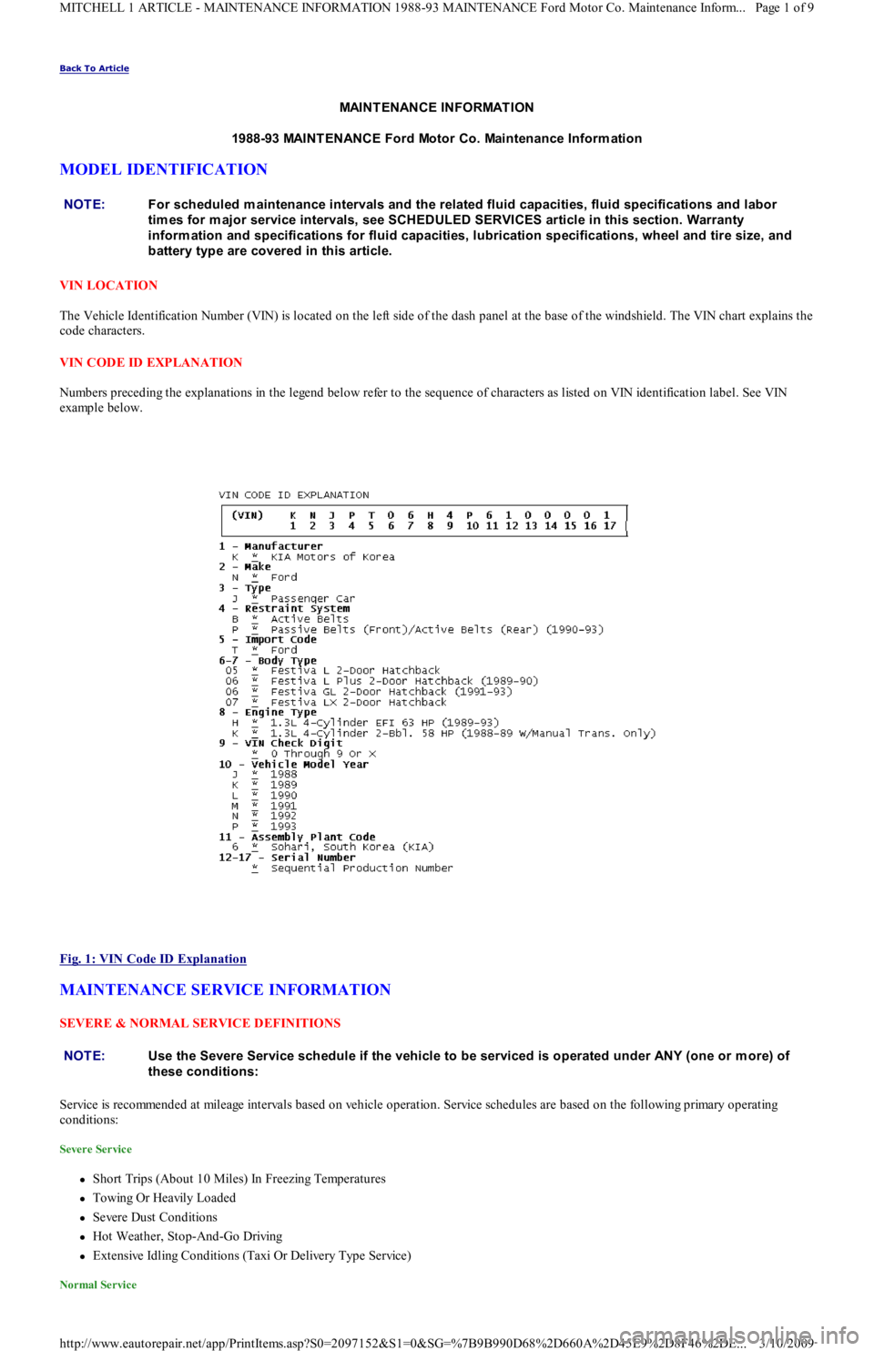
The Vehicle Identification Number (VIN) is located on the left side of the dash panel at the base of the windshield. The VIN chart explains the
code characters.
VIN CODE ID EXPLANATION
Numbers preceding the explanations in the legend below refer to the sequence of characters as listed on VIN identification label. See VIN
example below.
Fig. 1: VIN Code ID Explanation
MAINTENANCE SERVICE INFORMATION
SEVERE & NORMAL SERVICE DEFINITIONS
Service is recommended at mileage intervals based on vehicle operation. Service schedules are based on the following primary operating
conditions:
Severe Service
Short Trips (About 10 Miles) In Freezing Temperatures
Towing Or Heavily Loaded
Severe Dust Conditions
Hot Weather, Stop-And-Go Driving
Extensive Idling Conditions (Taxi Or Delivery Type Service)
Normal Service
NOTE:For scheduled m aintenance intervals and the related fluid capacities, fluid specifications and labor
tim es for m ajor service intervals, see SCHEDULED SERVICES article in this section. Warranty
inform ation and specifications for fluid capacities, lubrication specifications, wheel and tire size, and
battery type are covered in this article.
NOTE:Use the Severe Service schedule if the vehicle to be serviced is operated under ANY (one or m ore) of
these conditions:
Page 1 of 9 MITCHELL 1 ARTICLE - MAINTENANCE INFORMATION 1988-93 MAINTENANCE Ford Motor Co. Maintenance Inform...
3/10/2009 http://www.eautorepair.net/app/PrintItems.asp?S0=2097152&S1=0&SG=%7B9B990D68%2D660A%2D45E9%2D8F46%2DE
...