1991 FORD FESTIVA steering wheel
[x] Cancel search: steering wheelPage 20 of 454
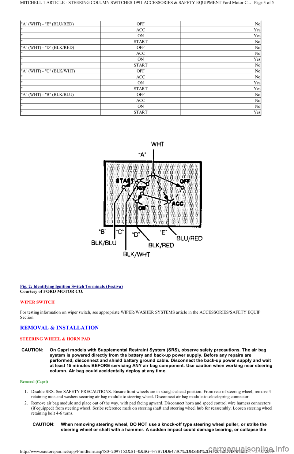
Fig. 2: Identifying Ignition Switch Terminals (Festiva)
Courtesy of FORD MOTOR CO.
WIPER SWITCH
For testing information on wiper switch, see appropriate WIPER/WASHER SYSTEMS article in the ACCESSORIES/SAFETY EQUIP
Section.
REMOVAL & INSTALLATION
STEERING WHEEL & HORN PAD
Removal (Capri)
1. Disable SRS. See SAFETY PRECAUTIONS. Ensure front wheels are in straight-ahead position. From rear of steering wheel, remove 4
retaining nuts and washers securing air bag module to steering wheel. Disconnect air bag module-to-clockspring connector.
2. Remove air bag module and place out of the way, with pad facing upward. Disconnect horn and speed control wire harness connectors
(if equipped) from steering wheel. Scribe reference mark on steering shaft and steering wheel hub for reassembly. Loosen steering wheel
retaining bolt 4-6 turns.
"A" (WHT) - "E" (BLU/RED)OFFNo
"ACCYes
"ONYes
"STARTNo
"A" (WHT) - "D" (BLK/RED)OFFNo
"ACCNo
"ONYes
"STARTNo
"A" (WHT) - "C" (BLK/WHT)OFFNo
"ACCNo
"ONYes
"STARTYes
"A" (WHT) - "B" (BLK/BLU)OFFNo
"ACCNo
"ONNo
"STARTYes
CAUTION: On Capri m odels with Supplem ental Restraint System (SRS), observe safety precautions. T he air bag
system is powered directly from the battery and back-up power supply. Before any repairs are
perform ed, disconnect and shield battery ground cable. Disconnect the back-up power supply and wait
at least 15 m inutes BEFORE servicing ANY air bag com ponent. Use caution when working near steering
colum n. Air bag could accidentally deploy at any tim e.
CAUT ION: When rem oving steering wheel, DO NOT use a knock-off type steering wheel puller, or strike the
steering wheel or shaft with a ham m er. A sudden im pact could dam age bearing, or collapse the
Page 3 of 5 MITCHELL 1 ARTICLE - STEERING COLUMN SWITCHES 1991 ACCESSORIES & SAFETY EQUIPMENT Ford Motor C
...
3/10/2009 http://www.eautorepair.net/app/PrintItems.asp?S0=2097152&S1=0&SG=%7B7DD6473C%2DB5BB%2D4F20%2D9D70%2D
...
Page 21 of 454
3. Position Steering Wheel Remover (T67L-3600-A) on steering wheel. Tighten bolt on remover until steering wheel is loose. Remove
steering wheel puller, steering wheel retaining bolt, and steering wheel.
Installation
1. Ensure front wheels are in straight-ahead position. Route clockspring wiring harness through steering wheel opening. Position steering
wheel on steering shaft and align reference marks.
2. Ensure clockspring wire is not pinched when positioning steering wheel. Install new steering wheel retaining bolt and tighten to
specification. See TORQUE SPECIFICATIONS table at end of article. Connect horn and speed control wiring connectors (if equipped)
to steering wheel.
3. Connect air bag module-to-clockspring connector. Install air bag module. Tighten air bag module retaining nuts to specification.
Activate SRS. See SAFETY PRECAUTIONS. Check AIR BAG light to ensure system is functioning properly.
Removal (Festiva)
From back of steering wheel, remove 2 screws securing horn pad. Disconnect horn wire from horn pad and remove pad. Remove steering
wheel nut. Scribe reference mark on steering shaft and steering wheel hub for reassembly. Using Steering Wheel Puller (T67L-3600-A),
remove steering wheel.
Installation
Position steering wheel on steering shaft and align reference marks. Be sure cutouts in rear cover engage turn signal canceling cam. To
complete installation, reverse removal procedure.
COMBINATION SW ITCH
Removal (Capri)
1. Disconnect negative battery cable. Remove lower steering column cover. Remove center access panel and trim cover under steering
column. Remove left side defroster connector tube. Remove steering column upper retaining bolts. Column will pivot downward and
rest on instrument panel brace.
2. Remove 2 switch retaining screws and remove switch. Grasp switch and lever and pull lever out of switch. Disconnect switch electrical
connectors and remove switch.
Installation
Align key with slot and install lever in switch assembly. Position switch on steering column and install retaining screws. To complete
installation, reverse removal procedure.
Removal (Festiva)
1. Disconnect negative battery cable. Remove steering wheel. See STEERING WHEEL & HORN PAD under REMOVAL &
INSTALLATION. Remove 4 screws from upper half of lower steering column cover and remove cover. Remove upper steering column
cover. Remove 5 clips from lower half of lower steering column cover and remove cover.
2. Release wiring harness clip and unplug 4 harness connectors from back of combination switch. From below steering column, loosen
band clamp securing switch hub to steering column jacket. Pull switch assembly from steering column.
Installation
Slide combination switch assembly onto steering column. Make sure switch assembly is seated and level against end of column jacket. To
complete installation, reverse removal procedure.
HEADLIGHT SWITCH
Removal & Installation (Capri)
1. Headlight off/on switch is located on left side of instrument panel bezel. Disconnect negative battery cable. Pull out center storage
compartment. Remove 2 upper screws, 2 lower screws and heater/radio bezel. Pull outward and remove trim covers located on both
sides of steering column.
2. Remove retaining screws and carefully pull instrument panel bezel partially away from dash. Disconnect electrical connector from
headlight switch. Depress tangs on both sides of switch and remove switch from bezel. To install, reverse removal procedure.
IGNITION SWITCH & LOCK CYLINDER
Removal (Capri)
1. Disconnect negative battery cable. Remove lower steering column cover. Remove center access panel and trim cover under steering
column. Remove left side defroster connector tube. Remove steering column upper retaining bolts. Column will pivot downward and
rest on instrument panel brace. steering colum n.
CAUT ION: Rem ove steering wheel carefully to avoid dam aging clockspring wiring, air bag m odule connector, or
accidentally turning clockspring. After steering wheel rem oval, tape clockspring in position to prevent
dam age and keep it from being turned accidentally.
CAUTION: Ensure that no wiring is pinched beneath steering colum n when lowered.
Page 4 of 5 MITCHELL 1 ARTICLE - STEERING COLUMN SWITCHES 1991 ACCESSORIES & SAFETY EQUIPMENT Ford Motor C
...
3/10/2009 http://www.eautorepair.net/app/PrintItems.asp?S0=2097152&S1=0&SG=%7B7DD6473C%2DB5BB%2D4F20%2D9D70%2D
...
Page 22 of 454
2. With ignition key inserted in lock assembly, rotate tumbler while pushing release pin with a .125" (3.17 mm) drift punch. Pull tumbler
assembly out of housing. Remove upper column cover. Remove column lock shield. Disconnect ignition switch electrical connector.
Remove switch retaining screws and remove switch.
Installation
Position ignition switch on column lock assembly. Make sure actuator pin of lock assembly fits into slot in ignition switch. To complete
installation, reverse removal procedure.
Removal & Installation (Festiva)
1. Disconnect negative battery cable. Remove 4 screws from upper half of lower steering column cover and remove cover. Remove upper
steering column cover. Remove 5 clips from lower half of lower steering column cover and remove cover.
2. Remove 4 steering column shield nuts and remove shield. Remove 2 shield bracket bolts and remove bracket. Remove air discharge duct
from below steering column. Remove steering column attaching nuts then lower steering column mounting bracket.
3. Remove tie strap securing key warning buzzer switch wires. Remove ignition switch attaching screw. Pull switch loose from switch
housing. Remove switch harness from routing clip and disconnect electrical connectors. Remove switch. To install, reverse removal
procedure.
TURN SIGNAL SWITCH
See COMBINATION SWITCH under REMOVAL & INSTALLATION.
WIPER SWITCH
Removal & Installation (Capri)
Remove center trim panel and lower steering column cover. Disconnect wiper switch electrical connector and pull wiring from routing clip.
Firmly grasp switch and lever and pull out to remove. To install, reverse removal procedure.
Removal & installation (Festiva)
See COMBINATION SWITCH under REMOVAL & INSTALLATION.
TORQUE SPECIFICATIONS
TORQUE SPECIFICATIONS CAUTION: Ensure that no wiring is pinched beneath steering colum n when it is lowered.
ApplicationFt. Lbs. (N.m)
Capri
Column Lock Shield Screw & Nut11-14 (15-19)
Ignition Lock Housing Bolt12-13 (16-18)
Steering Wheel Bolt23-33 (31-45)
Upper Column Retaining Bolts17-23 (23-31)
Festiva
Steering Wheel Nut29-36 (39-49)
Upper Column Retaining Bolts23-34 (31-46)
INCH Lbs. (N.m)
Capri
Ign it io n Swit ch Screw50-70 (5.6-7.9)
Capri & Festiva
Air Bag Module-To-Steering Wheel Nuts35-53 (4-6)
Copyr ight 2009 Mitchell Repair Information Company, LLC. All Rights Reserved.
Article GUID: A00028303
Page 5 of 5 MITCHELL 1 ARTICLE - STEERING COLUMN SWITCHES 1991 ACCESSORIES & SAFETY EQUIPMENT Ford Motor C
...
3/10/2009 http://www.eautorepair.net/app/PrintItems.asp?S0=2097152&S1=0&SG=%7B7DD6473C%2DB5BB%2D4F20%2D9D70%2D
...
Page 26 of 454
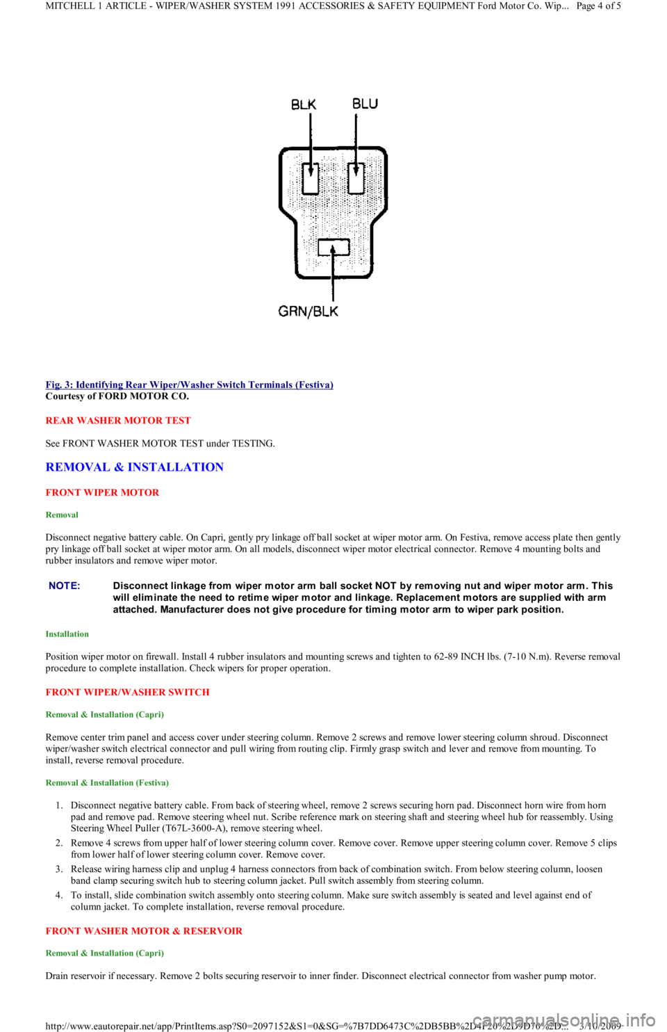
Fig. 3: Identifying Rear Wiper/Washer Switch Terminals (Festiva)
Courtesy of FORD MOTOR CO.
REAR WASHER MOTOR TEST
See FRONT WASHER MOTOR TEST under TESTING.
REMOVAL & INSTALLATION
FRONT WIPER MOTOR
Removal
Disconnect negative battery cable. On Capri, gently pry linkage off ball socket at wiper motor arm. On Festiva, remove access plate then gently
pry linkage off ball socket at wiper motor arm. On all models, disconnect wiper motor electrical connector. Remove 4 mounting bolts and
rubber insulators and remove wiper motor.
Installation
Position wiper motor on firewall. Install 4 rubber insulators and mounting screws and tighten to 62-89 INCH lbs. (7-10 N.m). Reverse removal
procedure to complete installation. Check wipers for proper operation.
FRONT WIPER/WASHER SWITCH
Removal & Installation (Capri)
Remove center trim panel and access cover under steering column. Remove 2 screws and remove lower steering column shroud. Disconnect
wiper/washer switch electrical connector and pull wiring from routing clip. Firmly grasp switch and lever and remove from mounting. To
install, reverse removal procedure.
Removal & Installation (Festiva)
1. Disconnect negative battery cable. From back of steering wheel, remove 2 screws securing horn pad. Disconnect horn wire from horn
pad and remove pad. Remove steering wheel nut. Scribe reference mark on steering shaft and steering wheel hub for reassembly. Using
Steering Wheel Puller (T67L-3600-A), remove steering wheel.
2. Remove 4 screws from upper half of lower steering column cover. Remove cover. Remove upper steering column cover. Remove 5 clips
from lower half of lower steering column cover. Remove cover.
3. Release wiring harness clip and unplug 4 harness connectors from back of combination switch. From below steering column, loosen
band clamp securing switch hub to steering column jacket. Pull switch assembly from steering column.
4. To install, slide combination switch assembly onto steering column. Make sure switch assembly is seated and level against end of
column jacket. To complete installation, reverse removal procedure.
FRONT WASHER MOTOR & RESERVOIR
Removal & Installation (Capri)
Drain reservoir if necessary. Remove 2 bolts securing reservoir to inner finder. Disconnect electrical connector from washer pump mo t o r.
NOTE:Disconnect linkage from wiper m otor arm ball socket NOT by rem oving nut and wiper m otor arm . This
will elim inate the need to retim e wiper m otor and linkage. Replacem ent m otors are supplied with arm
attached. Manufacturer does not give procedure for tim ing m otor arm to wiper park position.
Page 4 of 5 MITCHELL 1 ARTICLE - WIPER/WASHER SYSTEM 1991 ACCESSORIES & SAFETY EQUIPMENT Ford Motor Co. Wip
...
3/10/2009 http://www.eautorepair.net/app/PrintItems.asp?S0=2097152&S1=0&SG=%7B7DD6473C%2DB5BB%2D4F20%2D9D70%2D
...
Page 28 of 454
Back To Article
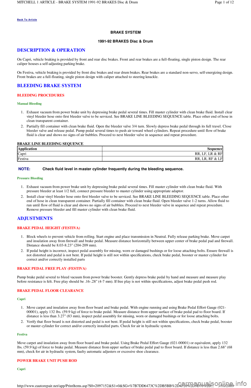
BRAKE SYST EM
1991-92 BRAKES Disc & Drum
DESCRIPTION & OPERATION
On Capri, vehicle braking is provided by front and rear disc brakes. Front and rear brakes are a full-floating, single piston design. The rear
caliper houses a self-adjusting parking brake.
On Festiva, vehicle braking is provided by front disc brakes and rear drum brakes. Rear brakes are a standard non-servo, self-en e r giz in g d e sign .
Front brakes are a full-floating, single piston design with caliper attached to steering knuckle.
BLEEDING BRAKE SYSTEM
BLEEDING PROCEDURES
Manual Bleeding
1. Exhaust vacuum from power brake unit by depressing brake pedal several times. Fill master cylinder with clean brake fluid. Install clear
vinyl bleeder hose onto first bleeder valve to be serviced. See BRAKE LINE BLEEDING SEQUENCE table. Place other end of hose in
clean transparent container.
2. Partially fill container with clean brake fluid. Open the bleeder valve 3/4 turn. Slowly depress brake pedal through its full travel. Close
bleeder valve and release pedal. Pump pedal several times to push air toward wheel cylinders. Repeat procedure until flow of brake
fluid is clear and shows no signs of air bubbles. Proceed to next bleeder valve in sequence and repeat procedure.
BRAKE LINE BLEEDING SEQUENCE
Pressure Bleeding
1. Exhaust vacuum from power brake unit by depressing brake pedal several times. Fill master cylinder with clean brake fluid. With
pressure bleeder at least 1/2 full, connect pressure bleeder to master cylinder using appropriate adaptor.
2. Install clear vinyl bleeder hose onto first bleeder valve to be serviced. See BRAKE LINE BLEEDING SEQUENCE table. Place other
end of hose in clean transparent container. Partially fill container with clean brake fluid. Open bleeder valve 1-2 turns. Allow fluid to
run until flow of fluid is clear and shows no signs of air bubbles. Proceed to next bleeder valve in sequence and repeat procedure.
Remove pressure bleeder and fill master cylinder with clean brake fluid.
ADJUSTMENTS
BRAKE PEDAL HEIGHT (FESTIVA)
1. Block wheels to prevent vehicle from rolling. Start engine and place transmission in Neutral. Fully release parking brake. Move carpet
and insulation away from firewall and brake pedal. Measure distance horizontally between upper center of brake pedal pad and firewall.
Distance should be 8.03-8.23" (204-209 mm).
2. If pedal height is incorrect, inspect pedal assembly for missing, worn or damaged bushings or for loose attaching bolts. Ensure firewall is
not distorted and pedal is not bent. If pedal height is still not within specifications, check brake pedal, booster or master cylinder for
correct and/or correctly installed parts
BRAKE PEDAL FREE PLAY (FESTIVA)
Pump brake pedal several to bleed vacuum from power brake booster. Gently depress brake pedal by hand and measure and measure play
before resistance is felt. Free play should be .16-.28" (4-7 mm). If free play is not within specifications, adjust brake pedal push rod.
BRAKE PEDAL FLOOR CLEARANCE
Capri
1. Move carpet and insulation away from floor board and brake pedal. With engine running and using Brake Pedal Effort Gauge (021-
00001), apply 132 lbs. (59.9 kg) of force to brake pedal. Measure distance from upper surface of brake pedal pad to floor board. If
distance is less than 3.27" (83 mm), inspect pedal assembly for missing, worn or damaged bushings or for loose attaching bolts.
2. Verify that floor board is not distorted and pedal is not bent. If pedal height is still not within specifications, check brake pedal, booster
or master cylinder for correct and/or correctly installed parts. Check for air in hydraulic system.
Festiva
Move carpet and insulation away from floor board and brake pedal. Using Brake Pedal Effort Gauge (021-00001) or equivalent, apply 132
lbs. (59.9 kg) of force to brake pedal. Measure distance from upper surface of brake pedal pad to floor board. If distance is less than 2.68" (68
mm), check for air in hydraulic system, faulty automatic adjusters or excessive shoe clearance.
POWER BRAKE UNIT PUSH ROD
Capri
ApplicationSequence
CapriRR, LF, LR & RF
FestivaRR, LR, RF & LF
NOTE:Check fluid level in m aster cylinder frequently during the bleeding sequence.
Page 1 of 12 MITCHELL 1 ARTICLE - BRAKE SYSTEM 1991-92 BRAKES Disc & Drum
3/10/2009 http://www.eautorepair.net/app/PrintItems.asp?S0=2097152&S1=0&SG=%7B7DD6473C%2DB5BB%2D4F20%2D9D70%2D
...
Page 33 of 454
Removal
Remove rotor and hub assembly from steering knuckle. Separate rotor, knuckle and hub. See FRONT BRAKE ROTOR & HUB under
REMOVAL & INSTALLATION. Press outer bearing from hub using Bearing Splitter (D84L-1123-A) and Shaft Protector (D80L-625-2).
Remove and discard outer grease seal. Pry inner wheel bearing grease seal from steering knuckle using a large screwdriver. Discard seal.
R e mo ve in n e r b e a r in g.
Bearing Preload
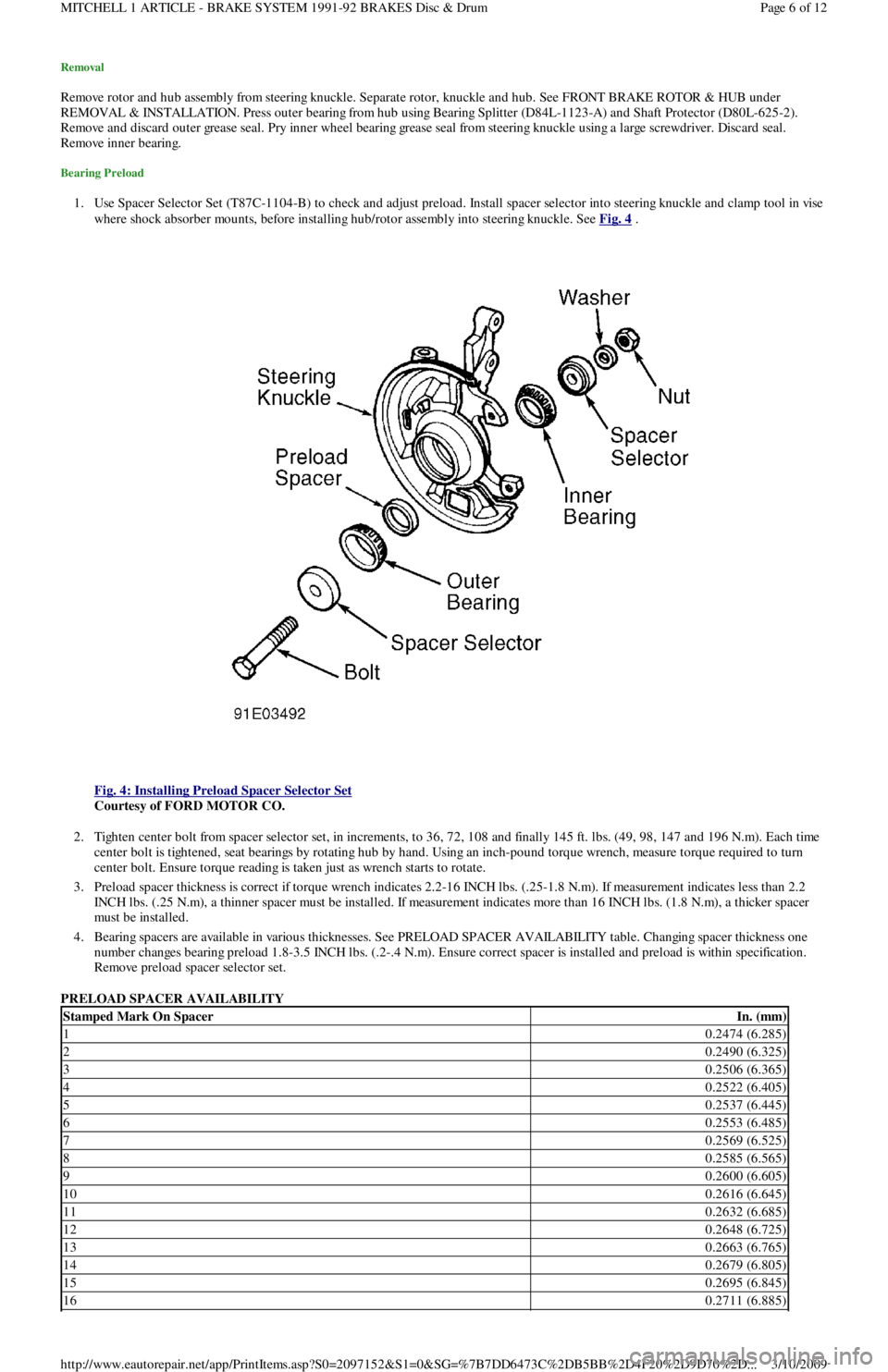
1. Use Spacer Selector Set (T87C-1104-B) to check and adjust preload. Install spacer selector into steering knuckle and clamp tool in vise
where shock absorber mounts, before installing hub/rotor assembly into steering knuckle. See Fig. 4
.
Fig. 4: Installing Preload Spacer Selector Set
Courtesy of FORD MOTOR CO.
2. Tighten center bolt from spacer selector set, in increments, to 36, 72, 108 and finally 145 ft. lbs. (49, 98, 147 and 196 N.m). Each time
center bolt is tightened, seat bearings by rotating hub by hand. Using an inch-pound torque wrench, measure torque required to turn
center bolt. Ensure torque reading is taken just as wrench starts to rotate.
3. Preload spacer thickness is correct if torque wrench indicates 2.2-16 INCH lbs. (.25-1.8 N.m). If measurement indicates less than 2.2
INCH lbs. (.25 N.m), a thinner spacer must be installed. If measurement indicates more than 16 INCH lbs. (1.8 N.m), a thicker spacer
must be installed.
4. Bearing spacers are available in various thicknesses. See PRELOAD SPACER AVAILABILITY table. Changing spacer thickness one
number changes bearing preload 1.8-3.5 INCH lbs. (.2-.4 N.m). Ensure correct spacer is installed and preload is within specification.
Remove preload spacer selector set.
PRELOAD SPACER AVAILABILITY
Stamped Mark On SpacerIn. (mm)
10.2474 (6.285)
20.2490 (6.325)
30.2506 (6.365)
40.2522 (6.405)
50.2537 (6.445)
60.2553 (6.485)
70.2569 (6.525)
80.2585 (6.565)
90.2600 (6.605)
100.2616 (6.645)
110.2632 (6.685)
120.2648 (6.725)
130.2663 (6.765)
140.2679 (6.805)
150.2695 (6.845)
160.2711 (6.885)
Page 6 of 12 MITCHELL 1 ARTICLE - BRAKE SYSTEM 1991-92 BRAKES Disc & Drum
3/10/2009 http://www.eautorepair.net/app/PrintItems.asp?S0=2097152&S1=0&SG=%7B7DD6473C%2DB5BB%2D4F20%2D9D70%2D
...
Page 34 of 454
Installation
1. Lubricate bearings with appropriate wheel bearing grease. Place inner bearing into steering knuckle. Install new inner bearing gr e a se
seal, and drive seal into place using appropriate seal installer.
2. Place original outer wheel bearing preload spacer (or spacer selected during preload inspection process) into steering knuckle bore.
Place outer wheel bearing into steering knuckle bore.
3. Liberally lubricate lip of NEW outer grease seal with appropriate lubricant. Drive seal into steering knuckle bore. Install brake rotor on
hub axle hub. Tighten bolts to 33-40 ft. lbs. (45-54 N.m). Position rotor/hub assembly into steering knuckle, and press assembly into
place using adapter from spacer selector set. To complete installation, reverse removal procedure.
REAR WHEEL BEARINGS
Removal & Installation
1. Raise and support rear axle. Remove wheel. Remove wheel bearing dust cap. On Capri, remove rear brake caliper. See REAR BRAKE
CALIPER & PADS under REMOVAL & INSTALLATION. On all models, carefully unstake rear axle lock nut using a chisel. DO NOT
damage threads on axle spindle. Remove and discard axle nut.
2. On Capri, remove rotor/hub assembly. On Festiva, remove brake drum/hub assembly. On all models, DO NOT allow outer wheel
bearing to fall out of hub. Remove inner bearing grease seal. Remove inner bearing. To install rear bearings, reverse removal procedure.
Adjust rear wheel bearings. See REAR AXLE BEARINGS under ADJUSTMENTS.
OVERHAUL
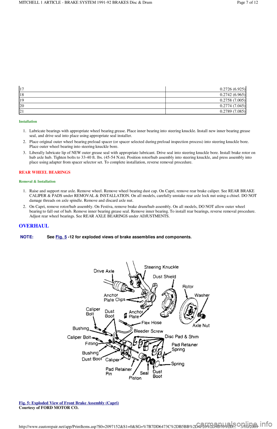
Fig. 5: Exploded View of Front Brake Assembly (Capri)
Courtesy of FORD MOTOR CO.
170.2726 (6.925)
180.2742 (6.965)
190.2758 (7.005)
200.2774 (7.045)
210.2789 (7.085)
NOTE:See Fig. 5
-12 for exploded views of brake assem blies and com ponents.
Page 7 of 12 MITCHELL 1 ARTICLE - BRAKE SYSTEM 1991-92 BRAKES Disc & Drum
3/10/2009 http://www.eautorepair.net/app/PrintItems.asp?S0=2097152&S1=0&SG=%7B7DD6473C%2DB5BB%2D4F20%2D9D70%2D
...
Page 38 of 454
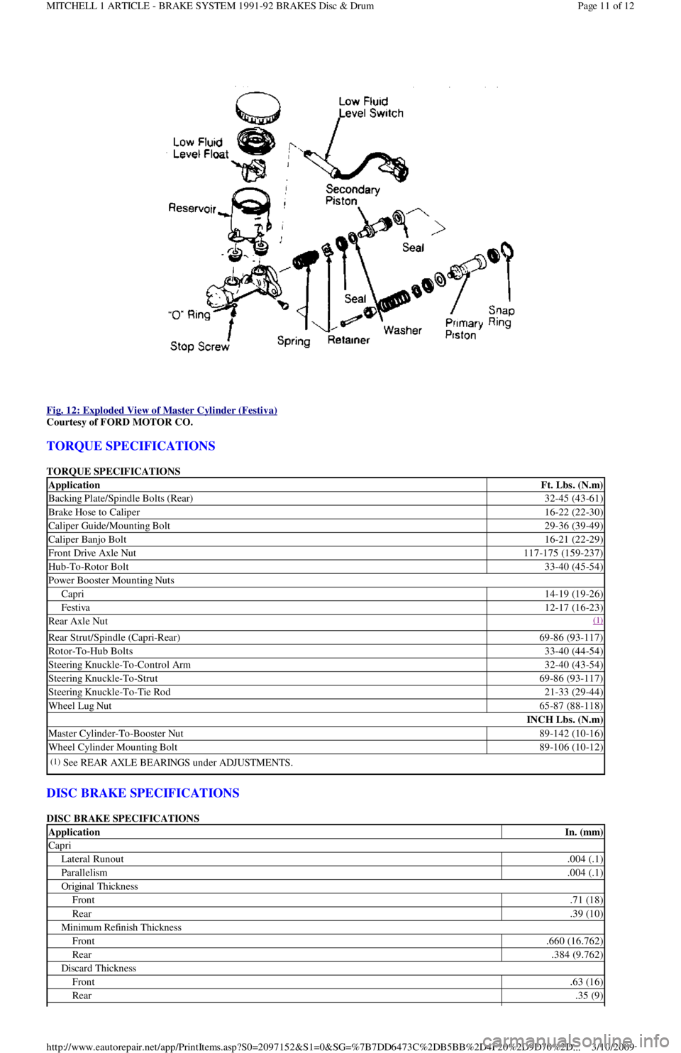
Fig. 12: Exploded View of Master Cylinder (Festiva)
Courtesy of FORD MOTOR CO.
TORQUE SPECIFICATIONS
TORQUE SPECIFICATIONS
DISC BRAKE SPECIFICATIONS
DISC BRAKE SPECIFICATIONS
ApplicationFt. Lbs. (N.m)
Backing Plate/Spindle Bolts (Rear)32-45 (43-61)
Brake Hose to Caliper16-22 (22-30)
Caliper Guide/Mounting Bolt29-36 (39-49)
Caliper Banjo Bolt16-21 (22-29)
Front Drive Axle Nut117-175 (159-237)
Hub-To-Rotor Bolt33-40 (45-54)
Power Booster Mounting Nuts
Capri14-19 (19-26)
Festiva12-17 (16-23)
Rear Axle Nut(1)
Rear Strut/Spindle (Capri-Rear)69-86 (93-117)
Rotor-To-Hub Bolts33-40 (44-54)
Steering Knuckle-To-Control Arm32-40 (43-54)
Steering Knuckle-To-Strut69-86 (93-117)
Steering Knuckle-To-Tie Rod21-33 (29-44)
Wheel Lug Nut65-87 (88-118)
INCH Lbs. (N.m)
Master Cylinder-To-Booster Nut89-142 (10-16)
Wheel Cylinder Mounting Bolt89-106 (10-12)
(1)See REAR AXLE BEARINGS under ADJUSTMENTS.
ApplicationIn. (mm)
Capri
Lateral Runout.004 (.1)
Parallelism.004 (.1)
Original Thickness
Front.71 (18)
Rear.39 (10)
Min imu m Refin ish Th ickn ess
Front.660 (16.762)
Rear.384 (9.762)
Discard Thickness
Front.63 (16)
Rear.35 (9)
Page 11 of 12 MITCHELL 1 ARTICLE - BRAKE SYSTEM 1991-92 BRAKES Disc & Drum
3/10/2009 http://www.eautorepair.net/app/PrintItems.asp?S0=2097152&S1=0&SG=%7B7DD6473C%2DB5BB%2D4F20%2D9D70%2D
...