1991 FORD FESTIVA steering wheel
[x] Cancel search: steering wheelPage 376 of 454
the WHEEL ALIGNMENT section.
OVERHAUL
STEERING GEAR
Disassembly
1. With steering gear removed from vehicle, place steering gear in a soft-jawed vise. Mark threaded portion of tie rod for reassembly.
Remove tie rod ends. Remove tie rod boots. Remove lock pins from both ends of rack. See Fig. 1
.
2. Remove tie rod ball socket from end of rack. Remove both tie rods. Remove lock nut from yoke plug. Remove yoke plug, spring and
yoke support. Use a small screwdriver to remove pinion oil seal from pinion shaft. Remove pinion bearing snap ring.
3. Remove pinion and bearing assembly. If necessary use Valve Body Puller (T78P-3504-B) to remove pinion and bearing assembly.
Remove rack from pinion side of housing. If lower pinion bearing needs replacing, use Blind Hole Bearing Puller (D80L-100-L) and
Slide Hammer (T50T-100-A) to remove.
4. Press bushing lock tabs into the 3 slots located at end of rack housing. Use Blind Hole Bearing Puller (D80L-100-L), to remove rack
support bushing from right end of rack housing.
Inspection
1. Check rubber boots, ball bearings and tooth surface of rack for wear or damage. Using a dial indicator and "V" blocks, check rack for
straightness. Maximum allowable runout is 0.012" (0.3 mm). If rack support bushings are worn, use a screwdriver to release the tab lock
on the side opposite the pinion. Use blind hole Bearing Puller (D80L-100R) with slide hammer to remove bushing.
2. Check tie rod ball joints for smooth operation. Replace parts as necessary. Check sliding surface of rack support and gear housing for
cracks or damage. Check rack bushing for excessive wear. Replace entire gear housing assembly if any of these parts are worn or
damaged.
Reassembly
1. Apply lithium grease to ball bearing, roller bearing, inside of gear housing, lip of oil seal, sliding surface and back of rack support,
sliding surface of rack bushing, rack pinion teeth and ball joints. Install rack support bushing into right end of rack housing. Ensure lock
tabs engage with slots in housing.
2. If previously removed, install a new lower pinion bearing using a bushing installer or a piece of wooden dowel stock. Carefully insert
non-toothed side of rack into left end of rack housing, with rack teeth facing pinion bore. Position rack in housing so rack protrudes
2.4" (62 mm) from the left side of housing. Install pinion and upper bearing assembly so that when bearing is seated, notch (for "U" joint
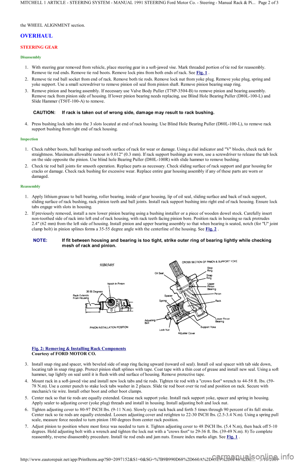
clamp bolt) in pinion splines forms a 35-55 degree angle with the centerline of the housing. See Fig. 2
.
Fig. 2: Removing & Installing Rack Components
Courtesy of FORD MOTOR CO.
3. Install snap ring and spacer, with beveled side of snap ring facing upward (toward oil seal). Install oil seal spacer with tab side down,
locating tab in snap ring gap. Protect pinion shaft splines with tape. Coat tape with a thin coat of grease and install new seal. Using a soft
hammer, tap lightly on seal until it is flush with end surface of housing. Remove protective tape.
4. Mount rack in a soft-jawed vise and install new lock tabs and tie rods. Tighten tie rod with a "crows foot" wrench to 44-58 ft. lbs. (59-
78 N.m). Use a center punch to stake lock tabs washer in 2 places. Slide tie rod boot over tie rod and position on rack. Secure with
mechanic's tie wire. Install other boot and other boot clamps.
5. Center rack so that tie rods are equally extended. Grease rack support yoke. Install rack support yoke, spacer and spring in housing.
Apply sealer to adjusting cover (yoke plug) threads and install in housing. Install adjusting bolt and lock nut.
6. Tighten adjusting cover to 80-97 INCH lbs. (9-11 N.m). Slowly cycle rack back and forth 5 times through 90 percent of its full stroke.
Center rack so tie rods are equally extended. Loosen adjusting cover and retighten to 22-30 INCH lbs. (2.5-3.4 N.m). Using a spring pull
scale, measure force needed to turn pinion 180 degrees from center rack position.
7. Adjust pinion to position where most force was needed to turn it. Tighten adjusting cover to 48 INCH lbs. (5.4 N.m), then back off 5-10
degrees. Hold adjusting bolt with a wrench and tighten the lock nut with a "crows foot" to 29-36 ft. lbs. (39-49 N.m). 8) To comp l et e
reassembly, reverse disassembly procedure. Install tie rod ends and jam nuts. Ensure index marks align. See Fig. 1
. CAUT ION: If rack is taken out of wrong side, dam age m ay result to rack bushing.
NOTE:If fit between housing and bearing is too tight, strike outer ring of bearing lightly while checking
m esh of rack and pinion.
Page 2 of 3 MITCHELL 1 ARTICLE - STEERING SYSTEM - MANUAL 1991 STEERING Ford Motor Co. - Steering - Manual Rack & Pi
...
3/10/2009 http://www.eautorepair.net/app/PrintItems.asp?S0=2097152&S1=0&SG=%7B9B990D68%2D660A%2D45E9%2D8F46%2DE
...
Page 377 of 454
WHEEL ALIGNMENT
After performing appropriate service procedures, refer to WHEEL ALIGNMENT SPECIFICATIONS & PROCEDURES article in the WHEEL
ALIGNMENT section.
TORQUE SPECIFICATIONS
TORQUE SPECIFICATIONS
ApplicationFt. Lbs. (N.m)
Pinion Adjusting Screw Lock Nut29-36 (39-49)
Mounting Bracket Bolt23-34 (31-46)
Tie Rod End Castle Nut26-30 (35-40)
Tie Rod-to-Rack Ball Joint43-58 (58-79)
Copyr ight 2009 Mitchell Repair Information Company, LLC. All Rights Reserved.
Article GUID: A00054859
Page 3 of 3 MITCHELL 1 ARTICLE - STEERING SYSTEM - MANUAL 1991 STEERING Ford Motor Co. - Steering - Manual Rack & Pi
...
3/10/2009 http://www.eautorepair.net/app/PrintItems.asp?S0=2097152&S1=0&SG=%7B9B990D68%2D660A%2D45E9%2D8F46%2DE
...
Page 378 of 454
Back To Article
ST EERING SYST EM - POWER
1991-92 ST EERING Ford Motor Co. - Steering - Power Rack & Pinion
DESCRIPTION & OPERATION
Power steering system consists of a rack and pinion steering gear, valve body, power steering pump, fluid reservoir and interconnecting
hydraulic lines. Pressure and return lines from pump are connected to valve body. A vane-type power steering pump draws fluid from the
steering reservoir. Fluid is compressed by rotor and vanes inside steering pump and sent to steering gear. Pressure is monitored and controlled
by a pressure switch and a control valve located inside of steering pump.
TROUBLE SHOOTING
Refer to TROUBLE SHOOTING - BASIC PROCEDURES article in the GENERAL TROUBLE SHOOTING section.
LUBRICATION
CAPACITY
Information is not available.
FLUID TYPE
Use Dexron-II ATF type fluid.
FLUID LEVEL CHECK
Check fluid level before engine is started, while fluid is still cool. Remove reservoir cap fluid indicator on steering pump. Check fluid level.
Fluid should be between the "L" and "H" marks on the level gauge dipstick. If fluid is needed, fill to the "L" mark on dipstick. Run engine until
warm and turn steering wheel fully in both directions about 10 times. Return steering to straight-ahead position and shut engine off. Ensure
fluid level is between "L" and "H" marks. Add fluid if necessary.
HYDRAULIC FLUID BLEEDING
1. Raise and support front of vehicle. Ensure pump reservoir is filled to specified level. With ignition coil wire disconnected, crank engine
and add fluid to steering pump until fluid level remains constant. While cranking engine, rotate steering from stop to stop. Recheck and
add fluid as necessary.
2. Start engine and allow to idle for several minutes. Turn steering wheel completely lock-to-lock several times. Check fluid level. Add
fluid as necessary. Continue this procedure until there is no bubbling or decrease in fluid level.
ADJUSTMENTS
BELT TENSION
On Festiva, remove air duct and air cleaner. On all models, loosen steering pump mounting pivot bolt and the adjusting bolt lock nut. Using
Belt Tension Gauge (021-0028A), fit gauge to longest available belt span for testing. Adjust belt to specification. See BELT TENSION
SPECIFICATIONS . Tighten adjuster lock nut to 32-45 ft. lbs. (43-61 N.m) on Capri or 27-38 ft. lbs. (37-52 N.m) on Festiva.
BELT TENSION SPECIFICATIONS
REMOVAL & INSTALLATION
STEERING GEAR
Removal
1. Disconnect negative battery cable. On Capri, mark and loosen intermediate lower U-joint. On Festiva, mark and remove steering gear
intermediate shaft connecting steering gear to column shaft. On all models, disconnect high pressure and return lines and plug them.
Loosen front wheel lug nuts.
2. Raise vehicle. Remove front wheels. Remove tie rod end cotter pins and nuts. Separate tie rod ends from steering knuckles using Tie
Rod Remover (T85M-3395-A). Remove tie rod end splash shields. Remove right fender splash shield. Remove front catalytic converter
nuts and separate converter from inlet pipe.
3. Place reference marks on tie rod end and tie rod for reassembly reference. Loosen tie rod jam nut and remove right tie rod end. Remove
steering gear mounting bolts and washers. Slide steering gear to the left and pull right tie rod through fender opening. Remove steering
gear by sliding it to the right.
Installation
Application
(1) Deflection: In.
(mm)Gauge Tension:
Lbs. (kg)
New Belt
Capri & Festiva.31-.35 (8-9)110-132 (50-60)
Used Belt
Capri.31-.35 (8-9)110-132 (50-60)
Festiva.35-.39 (9-10)95-110 (43-50)
(1)Apply approximately 22 lbs. (9.9 kg) of pressure.
Page 1 of 9 MITCHELL 1 ARTICLE - STEERING SYSTEM - POWER 1991-92 STEERING Ford Motor Co. - Steering - Power Rack & Pi
...
3/10/2009 http://www.eautorepair.net/app/PrintItems.asp?S0=2097152&S1=0&SG=%7B9B990D68%2D660A%2D45E9%2D8F46%2DE
...
Page 379 of 454
1. Position steering gear in its mounting position. Attach intermediate shaft to steering gear pinion and tighten clamp bolt to 13-20 ft. lbs.
(18-26 N.m). Guide intermediate shaft into steering column hole. Lower vehicle.
2. Lift steering gear and align intermediate shaft with universal joint and install clamp bolt. Raise vehicle. Install steering gear mounting
bolts and tighten to 23-34 ft. lbs. (31-46 N.m). Install right tie rod end, using marks made during removal for installation reference.
Attach tie rod ends to steering knuckles. Install tie rod end nuts and tighten to 22-33 ft. lbs. (29-44 N.m).
3. Install tie rod end cotter pins. Attach catalytic converter to inlet pipe and install attaching nuts. Tighten nuts to 23-34 ft. lbs. (31-46
N.m). Install tie rod end splash shields. Install right fender splash shield. install front wheels. Lower vehicle.
4. Connect high pressure and return lines. Connect negative battery cable. Add power steering fluid and bleed air from system and check
for leaks. See HYDRAULIC FLUID BLEEDING
under LUBRICATION.
POWER STEERING PUMP
Removal (Capri)
1. Remove right radiator support and brace. Remove pump drive belt. Disconnect intercooler outlet hose at throttle intake (if equipped).
R e mo ve gr o u n d wir e fr o m e n gin e l ift in g e ye .
2. Remove pressure and return hoses and plug. Remove wire from pressure switch. Remove adjusting screw, nut and block from pump
bracket. Remove pivot bolt. Remove bracket retaining bolts then remove pump.
Removal (Festiva)
Remove air duct and air cleaner. Disconnect electrical connector from fluid pressure switch on power steering pump. Disconnect and plug
return and pressure lines. Remove adjustment bolt. Remove lock nut, washer and bracket bolt. Loosen mounting bolt and disconnect drive
belt. Remove mounting bolt. Remove power steering pump.
Installation (Capri & Festiva)
To install pump, reverse removal procedure. Adjust steering belt tension. Tighten all nuts and bolts to specification. See TORQUE
SPECIFICATIONS . Add power steering fluid and bleed air from system and check for leaks. See HYDRAULIC FLUID BLEEDING
under LUBRICATION.
OVERHAUL
STEERING GEAR
Disassembly (Capri)
1. Remove steering gear and place in soft-jawed vise. Remove external hydraulic lines. See Fig. 1 . Remove mount brackets and rubber
mount bushings. Remove brass tubing seats using a self-tapping screw and 2 screwdrivers.
Page 2 of 9 MITCHELL 1 ARTICLE - STEERING SYSTEM - POWER 1991-92 STEERING Ford Motor Co. - Steering - Power Rack & Pi
...
3/10/2009 http://www.eautorepair.net/app/PrintItems.asp?S0=2097152&S1=0&SG=%7B9B990D68%2D660A%2D45E9%2D8F46%2DE
...
Page 385 of 454
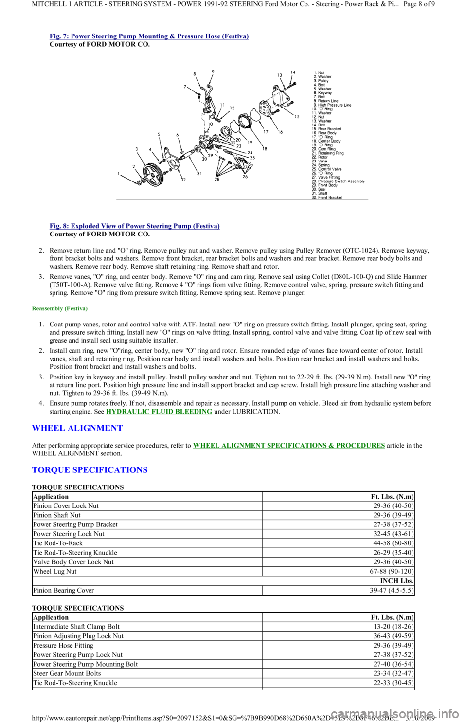
Fig. 7: Power Steering Pump Mounting & Pressure Hose (Festiva)
Courtesy of FORD MOTOR CO.
Fig. 8: Exploded View of Power Steering Pump (Festiva)
Courtesy of FORD MOTOR CO.
2. Remove return line and "O" ring. Remove pulley nut and washer. Remove pulley using Pulley Remover (OTC-1024). Remove keyway,
front bracket bolts and washers. Remove front bracket, rear bracket bolts and washers and rear bracket. Remove rear body bolts and
washers. Remove rear body. Remove shaft retaining ring. Remove shaft and rotor.
3. Remove vanes, "O" ring, and center body. Remove "O" ring and cam ring. Remove seal using Collet (D80L-100-Q) and Slide Hammer
( T5 0 T- 1 0 0 - A) . R e mo ve va l ve fit t in g. R e mo ve 4 "O" r in gs fr o m va l ve fit t in g. R e mo ve c o n t r o l va l ve , sp r in g, p r e ssu r e swit c h fit t ing a n d
spring. Remove "O" ring from pressure switch fitting. Remove spring seat. Remove plunger.
Reassembly (Festiva)
1. Coat pump vanes, rotor and control valve with ATF. Install new "O" ring on pressure switch fitting. Install plunger, spring seat, spring
and pressure switch fitting. Install new "O" rings on valve fitting. Install spring, control valve and valve fitting. Coat lip of new seal with
grease and install seal using suitable installer.
2. Install cam ring, new "O"ring, center body, new "O" ring and rotor. Ensure rounded edge of vanes face toward center of rotor. In st al l
vanes, shaft and retaining ring. Position rear body and install washers and bolts. Position rear bracket and install washers and bolts.
Position front bracket and install washers and bolts.
3. Position key in keyway and install pulley. Install pulley washer and nut. Tighten nut to 22-29 ft. lbs. (29-39 N.m). Install new "O" ring
at return line port. Position high pressure line and install support bracket and cap screw. Install high pressure line attaching washer and
nut. Tighten to 29-36 ft. lbs. (39-49 N.m).
4. Ensure pump rotates freely. If not, disassemble and repair as necessary. Install pump on vehicle. Bleed air from hydraulic system before
starting engine. See HYDRAULIC FLUID BLEEDING
under LUBRICATION.
WHEEL ALIGNMENT
After performing appropriate service procedures, refer to WHEEL ALIGNMENT SPECIFICATIONS & PROCEDURES article in the
WHEEL ALIGNMENT section.
TORQUE SPECIFICATIONS
TORQUE SPECIFICATIONS
TORQUE SPECIFICATIONS
ApplicationFt. Lbs. (N.m)
Pinion Cover Lock Nut29-36 (40-50)
Pinion Shaft Nut29-36 (39-49)
Power Steering Pump Bracket27-38 (37-52)
Power Steering Lock Nut32-45 (43-61)
Tie Rod-To-Rack44-58 (60-80)
Tie Rod-To-Steering Knuckle26-29 (35-40)
Valve Body Cover Lock Nut29-36 (40-50)
Wheel Lug Nut67-88 (90-120)
INCH Lbs.
Pinion Bearing Cover39-47 (4.5-5.5)
ApplicationFt. Lbs. (N.m)
Intermediate Shaft Clamp Bolt13-20 (18-26)
Pinion Adjusting Plug Lock Nut36-43 (49-59)
Pressure Hose Fitting29-36 (39-49)
Power Steering Pump Lock Nut27-38 (37-52)
Power Steering Pump Mounting Bolt27-40 (36-54)
Steer Gear Mount Bolts23-34 (32-47)
Tie Rod-To-Steering Knuckle22-33 (30-45)
Page 8 of 9 MITCHELL 1 ARTICLE - STEERING SYSTEM - POWER 1991-92 STEERING Ford Motor Co. - Steering - Power Rack & Pi
...
3/10/2009 http://www.eautorepair.net/app/PrintItems.asp?S0=2097152&S1=0&SG=%7B9B990D68%2D660A%2D45E9%2D8F46%2DE
...
Page 387 of 454
Back To Article
ST EERING COLUMN
1991 ST EERING Ford Motor Co. - Steering Colum ns
DESCRIPTION
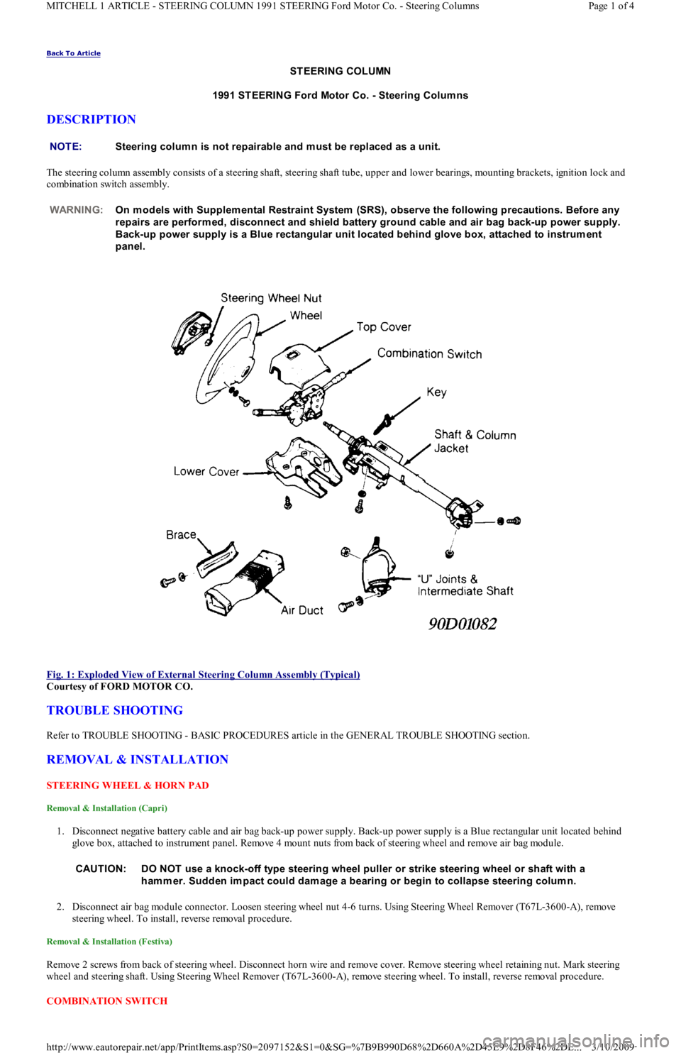
The steering column assembly consists of a steering shaft, steering shaft tube, upper and lower bearings, mounting brackets, ignition lock and
combination switch assembly.
Fig. 1: Exploded View of External Steering Column Assembly (Typical)
Courtesy of FORD MOTOR CO.
TROUBLE SHOOTING
Refer to TROUBLE SHOOTING - BASIC PROCEDURES article in the GENERAL TROUBLE SHOOTING section.
REMOVAL & INSTALLATION
STEERING WHEEL & HORN PAD
Removal & Installation (Capri)
1. Disconnect negative battery cable and air bag back-up power supply. Back-up power supply is a Blue rectangular unit located behind
glove box, attached to instrument panel. Remove 4 mount nuts from back of steering wheel and remove air bag module.
2. Disconnect air bag module connector. Loosen steering wheel nut 4-6 turns. Using Steering Wheel Remover (T67L-3600-A), remove
steering wheel. To install, reverse removal procedure.
Removal & Installation (Festiva)
Remove 2 screws from back of steering wheel. Disconnect horn wire and remove cover. Remove steering wheel retaining nut. Mark steering
wheel and steering shaft. Using Steering Wheel Remover (T67L-3600-A), remove steering wheel. To install, reverse removal procedure.
COMBINATION SW ITCH NOTE:Steering colum n is not repairable and m ust be replaced as a unit.
WARNING:On m odels with Supplem ental Restraint System (SRS), observe the following precautions. Before any
repairs are perform ed, disconnect and shield battery ground cable and air bag back-up power supply.
Back-up power supply is a Blue rectangular unit located behind glove box, attached to instrum ent
panel.
CAUT ION: DO NOT use a knock-off type steering wheel puller or strike steering wheel or shaft with a
ham m er. Sudden im pact could dam age a bearing or begin to collapse steering colum n.
Page 1 of 4 MITCHELL 1 ARTICLE - STEERING COLUMN 1991 STEERING Ford Motor Co. - Steering Columns
3/10/2009 http://www.eautorepair.net/app/PrintItems.asp?S0=2097152&S1=0&SG=%7B9B990D68%2D660A%2D45E9%2D8F46%2DE
...
Page 388 of 454
Removal & Installation (Capri)
Disconnect negative battery cable. With steering wheel removed, remove screws from lower column cover and remove lower cover. Remove
steering column upper retaining bolts. Steering column will rest on instrument panel bracket. Release wiring harness clip and unplug
connectors. Remove 2 switch retaining screws and remove switch from steering column. To install, reverse removal procedure.
Removal & Installation (Festiva)
Disconnect negative battery cable. With steering wheel removed, remove screws from lower column cover and remove both upper and lower
cover. Release wiring harness clip and unplug connectors. Loosen band clamp securing switch hub to steering column jacket. Remove swit c h
from steering column. To install, reverse removal procedure.
IGNITION SWITCH & LOCK
Removal & Installation (Capri Ignition Switch)
1. Disconnect negative battery cable. With steering wheel removed, remove upper and lower column covers. Remove center access panel
and trim panel under steering wheel. Remove left side defroster connector tube.
2. Remove steering column upper attaching bolts. Lower steering column onto instrument panel brace. Remove ignition tumbler. With
ignition key inserted, rotate tumbler while pushing release pin with .125" (3.17 mm) drift. Pull tumbler out of ignition lock housing.
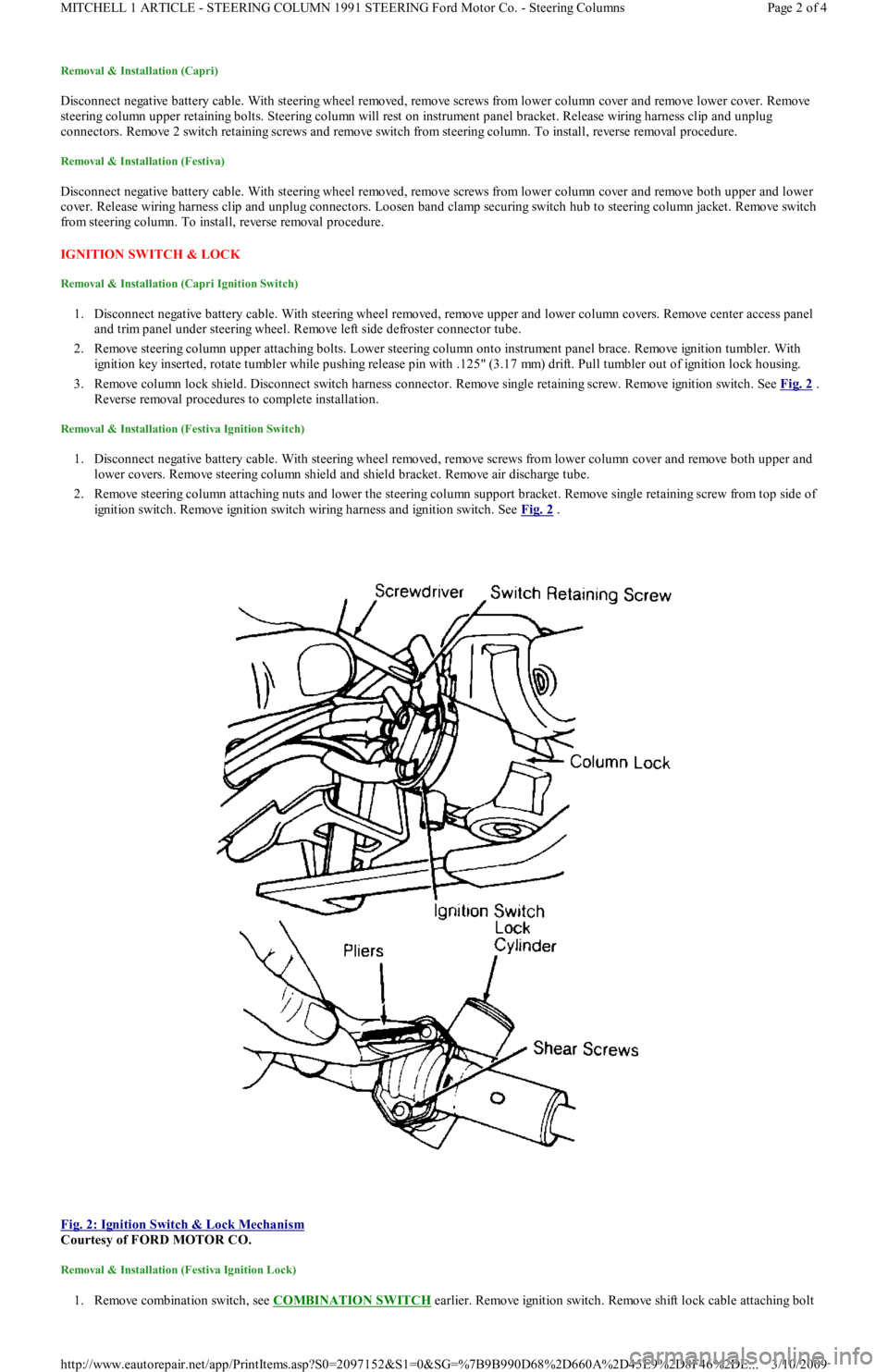
3. Remove column lock shield. Disconnect switch harness connector. Remove single retaining screw. Remove ignition switch. See Fig. 2
.
Reverse removal procedures to complete installation.
Removal & Installation (Festiva Ignition Switch)
1. Disconnect negative battery cable. With steering wheel removed, remove screws from lower column cover and remove both upper and
lower covers. Remove steering column shield and shield bracket. Remove air discharge tube.
2. Remove steering column attaching nuts and lower the steering column support bracket. Remove single retaining screw from top side of
ignition switch. Remove ignition switch wiring harness and ignition switch. See Fig. 2
.
Fig. 2: Ignition Switch & Lock Mechanism
Courtesy of FORD MOTOR CO.
Removal & Installation (Festiva Ignition Lock)
1. Remove combination switch, see COMBINATION SW ITCH earlier. Remove ignition switch. Remove shift lock cable attaching bolt
Page 2 of 4 MITCHELL 1 ARTICLE - STEERING COLUMN 1991 STEERING Ford Motor Co. - Steering Columns
3/10/2009 http://www.eautorepair.net/app/PrintItems.asp?S0=2097152&S1=0&SG=%7B9B990D68%2D660A%2D45E9%2D8F46%2DE
...
Page 389 of 454
and disconnect cable from lock housing. Using slim-nose locking pliers, grip and remove round headed shear screws securing column
lock housing and cap to column jacket. See Fig. 2
.
2. Remove lock housing. To install lock housing, position lock cylinder and cap on column jacket. Using new screws, tighten only enough
to hold lock housing in position. Use ignition key to ensure lock works correctly without binding. Adjust switch if necessary. Tighten
shear screws until heads break off. Install ignition switch in cylinder. Reverse removal procedures to complete installation.
STEERING COLUMN
Removal & Installation (Capri)
1. Place wheels in a straight-ahead position. Remove ignition key and lock steering wheel. Disconnect negative battery cable and air bag
back-up power supply. Back-up power supply is a Blue rectangular unit located behind glove box, attached to instrument panel.
2. Remove air bag module from steering wheel. Remove steering column access cover and trim panel. Remove defroster duct connecting
hose. Remove steering column lower shroud. Loosen lower steering c o l u mn r e t a in in g n u t s. R e mo ve st e e r in g c o l u mn u p p e r r e t a in in g
nuts.
3. Remove ignition lock shield and ignition switch mount screw. Disconnect all necessary electrical connectors. Mark and remove steering
shaft universal joint bolt. Remove steering column from instrument panel. To install, reverse removal procedure. Once steering column
is completely installed, check all switches and functions for proper operation.
Removal (Festiva)
1. Disconnect battery ground cable. Place wheels in a straight-ahead position. Remove steering wheel, upper and lower column covers,
combination switch, ignition switch and harness connectors.
2. Remove steering column shield and air duct from below steering column. Remove 2 steering column upper mounting bracket-to-
instrument panel crossmember nuts.
3. Lower upper end of column as necessary to gain access to intermediate shaft upper "U" joint. Mark steering shaft and upper "U" jo in t fo r
reassembly reference.
4. Remove "U" joint attaching bolt. Loosen 2 steering column hinge bracket-to-clutch/brake pedal support nuts. Remove steering column
with upper "U" joint by pulling toward passenger compartment.
Installation (Festiva)
1. Align marks made during removal and install column with intermediate shaft upper "U" joint over intermediate shaft. Install, but do not
tighten, "U" joint clamp bolt.
2. Install and tighten hinge bracket nuts. Install shim clips on column upper bracket flanges (if removed). Position upper end of steering
column to instrument panel mounting studs.
3. Install upper bracket retaining nuts. Turn steering wheel lock-to-lock several times to align "U" joint splines. Tighten "U" joint clamp
bolt.
4. Install air duct and instrument panel brace. Install harness connectors, ignition switch, combination switch, upper and lower column
covers and steering wheel.
OVERHAUL
STEERING COLUMN
Disassembly & Reassembly (Capri)
1. Remove steering column. See STEERING COLUMN under REMOVAL & INSTALLATION. Position steering column in soft-jawed
vise. Using Steering Wheel Remover (T67L-3600-A), remove steering wheel. Put 2 strips of tape on air bag clockspring, to avoid
rotation.
2. Remove 3 clockspring retaining screws and remove clockspring. With ignition key installed, rotate tumbler to Run position while
pushing tumbler release pin with .125" (3.17 mm) drift. Remove tumbler and upper column shroud. Remove key warning switch.
3. Remove bearing plate. Remove and discard snap ring located at front end of steering column. Remove multifunction switch. Remove
column lock and upper bearing using a suitable bearing puller. To reassemble, reverse disassembly procedure.
Disassembly (Festiva)
Disassembly of steering column assembly is not recommended by manufacturer. If any components are found defective, replace steering
column assembly.
Inspection (Festiva)
1. Measure steering shaft for signs of collapse. Steering shaft length should be between 23.86-23.94" (606-608 mm). If measurement is not
within specification, replace steering column assembly.
2. Check for steering shaft side play. Any detectable side play can adversely affect steering control. If side play in excess of .03" (.75 mm)
is present, bearings are badly worn. Replace steering column assembly.
Reassembly (Festiva)
NOTE:If steering rack and interm ediate shaft are also rem oved, "U" joints and interm ediate shaft m ust be
m arked for reassem bly reference. Both ends of shaft are identical.
CAUT ION: If steering shaft shear pins break during housing or bearing rem oval, the com plete shaft and colum n
m ust be replaced. T o determ ine if pins have sheared, m easure steering shaft from top end of shaft to
center of U-
joint bearing. If length is less than 24.23" (615.7 m m ) or greater than 24.66" (617.7 m m ), pins
have sheared.
Page 3 of 4 MITCHELL 1 ARTICLE - STEERING COLUMN 1991 STEERING Ford Motor Co. - Steering Columns
3/10/2009 http://www.eautorepair.net/app/PrintItems.asp?S0=2097152&S1=0&SG=%7B9B990D68%2D660A%2D45E9%2D8F46%2DE
...