1991 FORD FESTIVA height adjustment
[x] Cancel search: height adjustmentPage 28 of 454
Back To Article
BRAKE SYST EM
1991-92 BRAKES Disc & Drum
DESCRIPTION & OPERATION
On Capri, vehicle braking is provided by front and rear disc brakes. Front and rear brakes are a full-floating, single piston design. The rear
caliper houses a self-adjusting parking brake.
On Festiva, vehicle braking is provided by front disc brakes and rear drum brakes. Rear brakes are a standard non-servo, self-en e r giz in g d e sign .
Front brakes are a full-floating, single piston design with caliper attached to steering knuckle.
BLEEDING BRAKE SYSTEM
BLEEDING PROCEDURES
Manual Bleeding
1. Exhaust vacuum from power brake unit by depressing brake pedal several times. Fill master cylinder with clean brake fluid. Install clear
vinyl bleeder hose onto first bleeder valve to be serviced. See BRAKE LINE BLEEDING SEQUENCE table. Place other end of hose in
clean transparent container.
2. Partially fill container with clean brake fluid. Open the bleeder valve 3/4 turn. Slowly depress brake pedal through its full travel. Close
bleeder valve and release pedal. Pump pedal several times to push air toward wheel cylinders. Repeat procedure until flow of brake
fluid is clear and shows no signs of air bubbles. Proceed to next bleeder valve in sequence and repeat procedure.
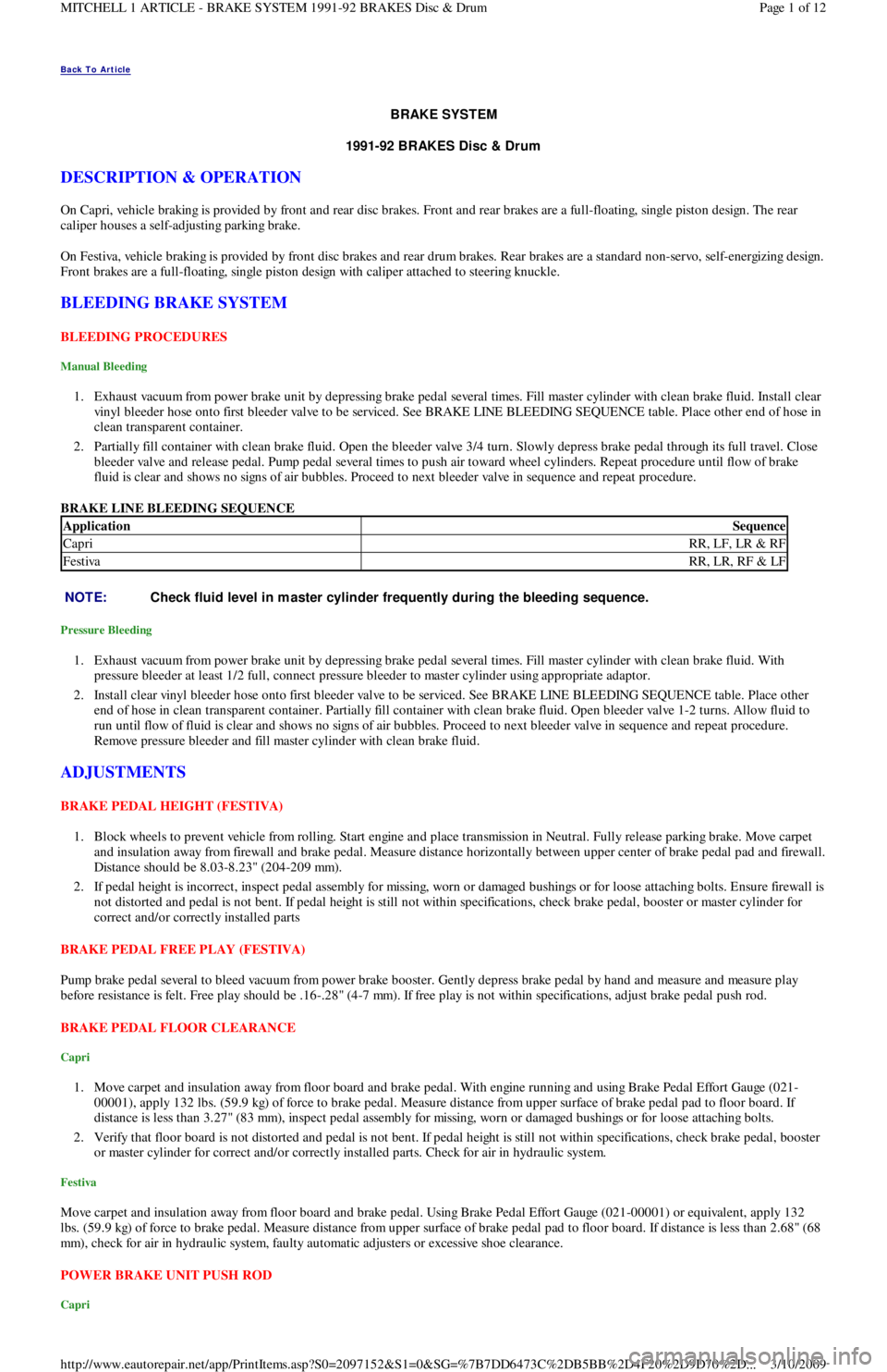
BRAKE LINE BLEEDING SEQUENCE
Pressure Bleeding
1. Exhaust vacuum from power brake unit by depressing brake pedal several times. Fill master cylinder with clean brake fluid. With
pressure bleeder at least 1/2 full, connect pressure bleeder to master cylinder using appropriate adaptor.
2. Install clear vinyl bleeder hose onto first bleeder valve to be serviced. See BRAKE LINE BLEEDING SEQUENCE table. Place other
end of hose in clean transparent container. Partially fill container with clean brake fluid. Open bleeder valve 1-2 turns. Allow fluid to
run until flow of fluid is clear and shows no signs of air bubbles. Proceed to next bleeder valve in sequence and repeat procedure.
Remove pressure bleeder and fill master cylinder with clean brake fluid.
ADJUSTMENTS
BRAKE PEDAL HEIGHT (FESTIVA)
1. Block wheels to prevent vehicle from rolling. Start engine and place transmission in Neutral. Fully release parking brake. Move carpet
and insulation away from firewall and brake pedal. Measure distance horizontally between upper center of brake pedal pad and firewall.
Distance should be 8.03-8.23" (204-209 mm).
2. If pedal height is incorrect, inspect pedal assembly for missing, worn or damaged bushings or for loose attaching bolts. Ensure firewall is
not distorted and pedal is not bent. If pedal height is still not within specifications, check brake pedal, booster or master cylinder for
correct and/or correctly installed parts
BRAKE PEDAL FREE PLAY (FESTIVA)
Pump brake pedal several to bleed vacuum from power brake booster. Gently depress brake pedal by hand and measure and measure play
before resistance is felt. Free play should be .16-.28" (4-7 mm). If free play is not within specifications, adjust brake pedal push rod.
BRAKE PEDAL FLOOR CLEARANCE
Capri
1. Move carpet and insulation away from floor board and brake pedal. With engine running and using Brake Pedal Effort Gauge (021-
00001), apply 132 lbs. (59.9 kg) of force to brake pedal. Measure distance from upper surface of brake pedal pad to floor board. If
distance is less than 3.27" (83 mm), inspect pedal assembly for missing, worn or damaged bushings or for loose attaching bolts.
2. Verify that floor board is not distorted and pedal is not bent. If pedal height is still not within specifications, check brake pedal, booster
or master cylinder for correct and/or correctly installed parts. Check for air in hydraulic system.
Festiva
Move carpet and insulation away from floor board and brake pedal. Using Brake Pedal Effort Gauge (021-00001) or equivalent, apply 132
lbs. (59.9 kg) of force to brake pedal. Measure distance from upper surface of brake pedal pad to floor board. If distance is less than 2.68" (68
mm), check for air in hydraulic system, faulty automatic adjusters or excessive shoe clearance.
POWER BRAKE UNIT PUSH ROD
Capri
ApplicationSequence
CapriRR, LF, LR & RF
FestivaRR, LR, RF & LF
NOTE:Check fluid level in m aster cylinder frequently during the bleeding sequence.
Page 1 of 12 MITCHELL 1 ARTICLE - BRAKE SYSTEM 1991-92 BRAKES Disc & Drum
3/10/2009 http://www.eautorepair.net/app/PrintItems.asp?S0=2097152&S1=0&SG=%7B7DD6473C%2DB5BB%2D4F20%2D9D70%2D
...
Page 112 of 454
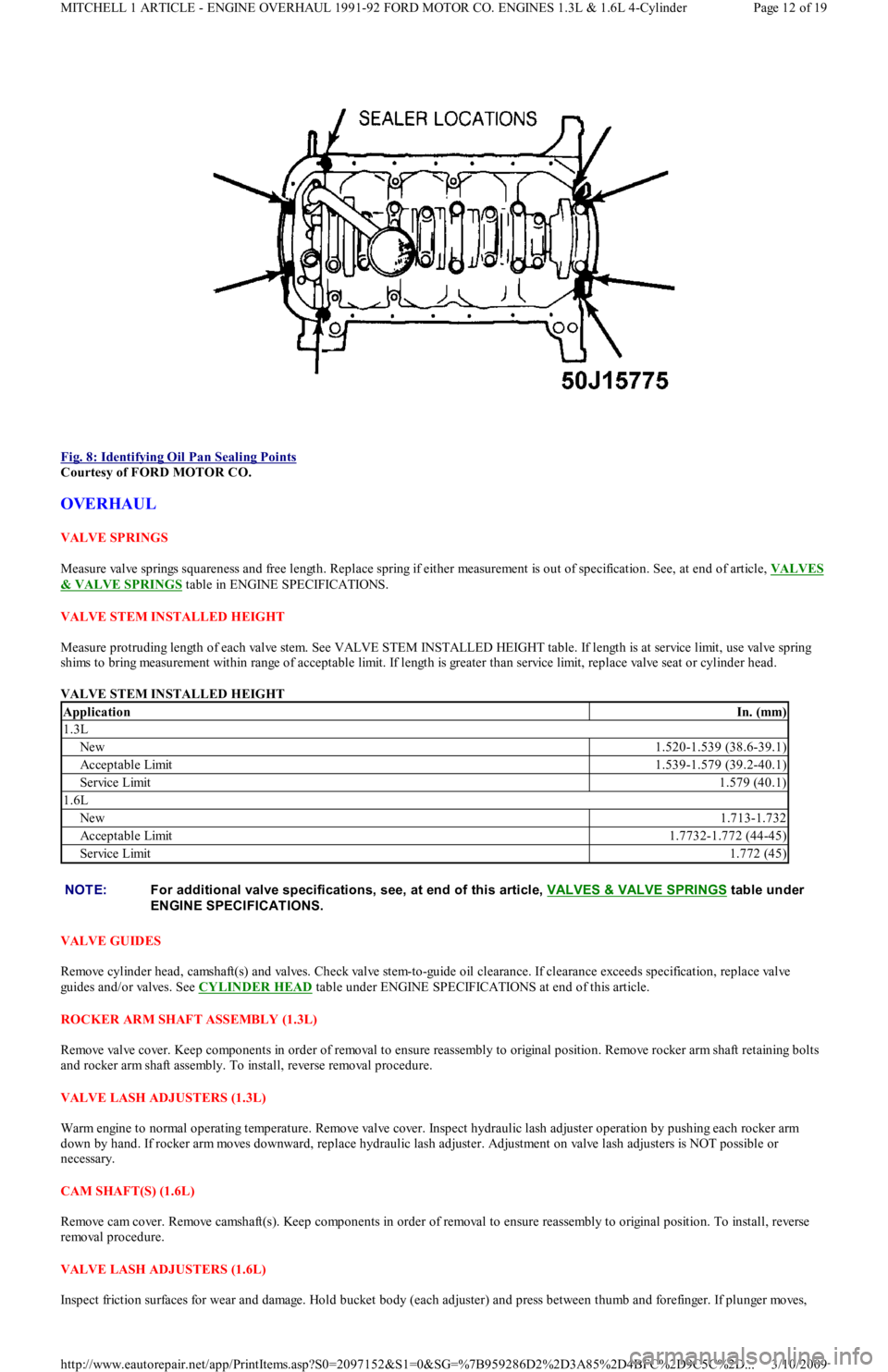
Fig. 8: Identifying Oil Pan Sealing Points
Courtesy of FORD MOTOR CO.
OVERHAUL
VALVE SPRINGS
Measure valve springs squareness and free length. Replace spring if either measurement is out of specification. See, at end of article, VALVES
& VALVE SPRINGS table in ENGINE SPECIFICATIONS.
VALVE STEM INSTALLED HEIGHT
Measure protruding length of each valve stem. See VALVE STEM INSTALLED HEIGHT table. If length is at service limit, use valve spring
shims to bring measurement within range of acceptable limit. If length is greater than service limit, replace valve seat or cylinder head.
VALVE STEM INSTALLED HEIGHT
VALVE GUIDES
Remove cylinder head, camshaft(s) and valves. Check valve stem-to-guide oil clearance. If clearance exceeds specification, replace valve
guides and/or valves. See CYLINDER HEAD
table under ENGINE SPECIFICATIONS at end of this article.
ROCKER ARM SHAFT ASSEMBLY (1.3L)
Remove valve cover. Keep components in order of removal to ensure reassembly to original position. Remove rocker arm shaft retaining bolts
and rocker arm shaft assembly. To install, reverse removal procedure.
VALVE LASH ADJUSTERS (1.3L)
Warm engine to normal operating temperature. Remove valve cover. Inspect hydraulic lash adjuster operation by pushing each rocker arm
down by hand. If rocker arm moves downward, replace hydraulic lash adjuster. Adjustment on valve lash adjusters is NOT possible or
necessary.
CAM SHAFT(S) (1.6L)
Remove cam cover. Remove camshaft(s). Keep components in order of removal to ensure reassembly to original position. To install, reverse
removal procedure.
VALVE LASH ADJUSTERS (1.6L)
Inspect friction surfaces for wear and damage. Hold bucket body (each adjuster) and press between thumb and forefinger. If plunge r mo ve s,
ApplicationIn. (mm)
1.3L
New1.520-1.539 (38.6-39.1)
Acceptable Limit1.539-1.579 (39.2-40.1)
Service Limit1.579 (40.1)
1.6L
New1.713-1.732
Acceptable Limit1.7732-1.772 (44-45)
Service Limit1.772 (45)
NOTE:For additional valve specifications, see, at end of this article, VALVES & VALVE SPRINGS
table under
ENGINE SPECIFICAT IONS.
Page 12 of 19 MITCHELL 1 ARTICLE - ENGINE OVERHAUL 1991-92 FORD MOTOR CO. ENGINES 1.3L & 1.6L 4-Cylinder
3/10/2009 http://www.eautorepair.net/app/PrintItems.asp?S0=2097152&S1=0&SG=%7B959286D2%2D3A85%2D4BFC%2D9C5C%2D
...
Page 248 of 454
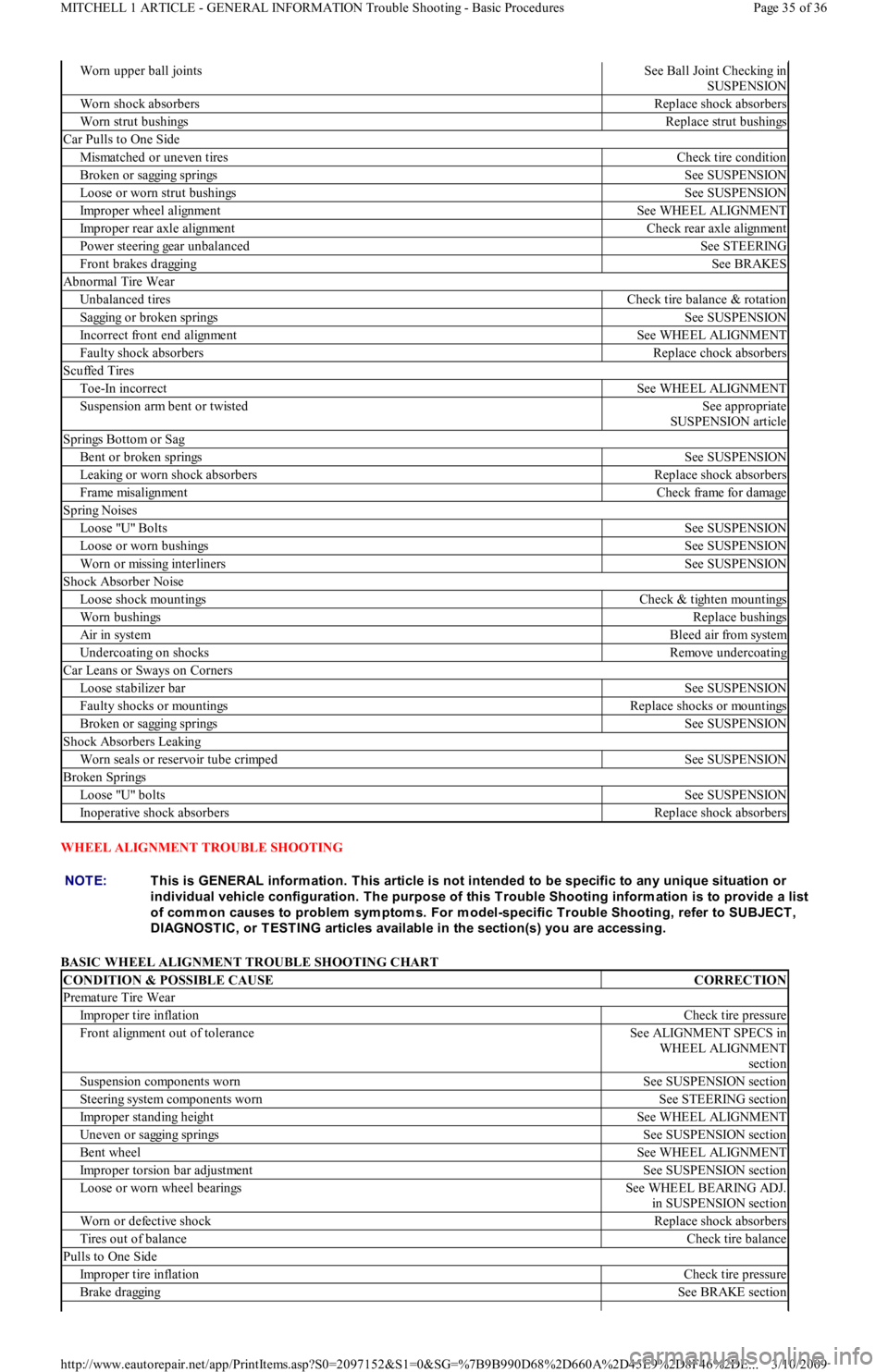
WHEEL ALIGNMENT TROUBLE SHOOTING
BASIC WHEEL ALIGNMENT TROUBLE SHOOTING CHART
Worn upper ball jointsSee Ball Joint Checking in
SUSPENSION
Worn shock absorbersReplace shock absorbers
Worn strut bushingsReplace strut bushings
Car Pulls to One Side
Mismatched or uneven tiresCheck tire condition
Broken or sagging springsSee SUSPENSION
Loose or worn strut bushingsSee SUSPENSION
Improper wheel alignmentSee WHEEL ALIGNMENT
Improper rear axle alignmentCheck rear axle alignment
Power steering gear unbalancedSee STEERING
Front brakes draggingSee BRAKES
Abnormal Tire Wear
Unbalanced tiresCheck tire balance & rotation
Sagging or broken springsSee SUSPENSION
Incorrect front end alignmentSee WHEEL ALIGNMENT
Faulty shock absorbersReplace chock absorbers
Scuffed Tires
Toe-In incorrectSee WHEEL ALIGNMENT
Suspension arm bent or twistedSee appropriate
SUSPENSION article
Springs Bottom or Sag
Bent or broken springsSee SUSPENSION
Leaking or worn shock absorbersReplace shock absorbers
Frame misalignmentCheck frame for damage
Spring Noises
Lo o se "U" Bo l t sSee SUSPENSION
Loose or worn bushingsSee SUSPENSION
Worn or missing interlinersSee SUSPENSION
Shock Absorber Noise
Loose shock mountingsCheck & tighten mountings
Worn bushingsReplace bushings
Air in systemBleed air from system
Undercoating on shocksRemove undercoating
Car Leans or Sways on Corners
Loose stabilizer barSee SUSPENSION
Faulty shocks or mountingsReplace shocks or mountings
Broken or sagging springsSee SUSPENSION
Shock Absorbers Leaking
Worn seals or reservoir tube crimpedSee SUSPENSION
Broken Springs
Lo o se "U" b o l t sSee SUSPENSION
Inoperative shock absorbersReplace shock absorbers
NOTE:This is GENERAL inform ation. This article is not intended to be specific to any unique situation or
individual vehicle configuration. T he purpose of this T rouble Shooting inform ation is to provide a list
of com m on causes to problem sym ptom s. For m odel-specific T rouble Shooting, refer to SUBJECT ,
DIAGNOST IC, or T EST ING articles available in the section(s) you are accessing.
CONDITION & POSSIBLE CAUSECORRECTION
Premature Tire Wear
Improper tire inflationCheck tire pressure
Front alignment out of toleranceSee ALIGNMENT SPECS in
WHEEL ALIGNMENT
section
Suspension components wornSee SUSPENSION section
Steering system components wornSee STEERING section
Improper standing heightSee WHEEL ALIGNMENT
Uneven or sagging springsSee SUSPENSION section
Bent wheelSee WHEEL ALIGNMENT
Improper torsion bar adjustmentSee SUSPENSION section
Loose or worn wheel bearingsSee WHEEL BEARING ADJ.
in SUSPENSION section
Worn or defective shockReplace shock absorbers
Tires out of balanceCheck tire balance
Pulls to One Side
Improper tire inflationCheck tire pressure
Brake draggingSee BRAKE section
Page 35 of 36 MITCHELL 1 ARTICLE - GENERAL INFORMATION Trouble Shooting - Basic Procedures
3/10/2009 http://www.eautorepair.net/app/PrintItems.asp?S0=2097152&S1=0&SG=%7B9B990D68%2D660A%2D45E9%2D8F46%2DE
...
Page 303 of 454
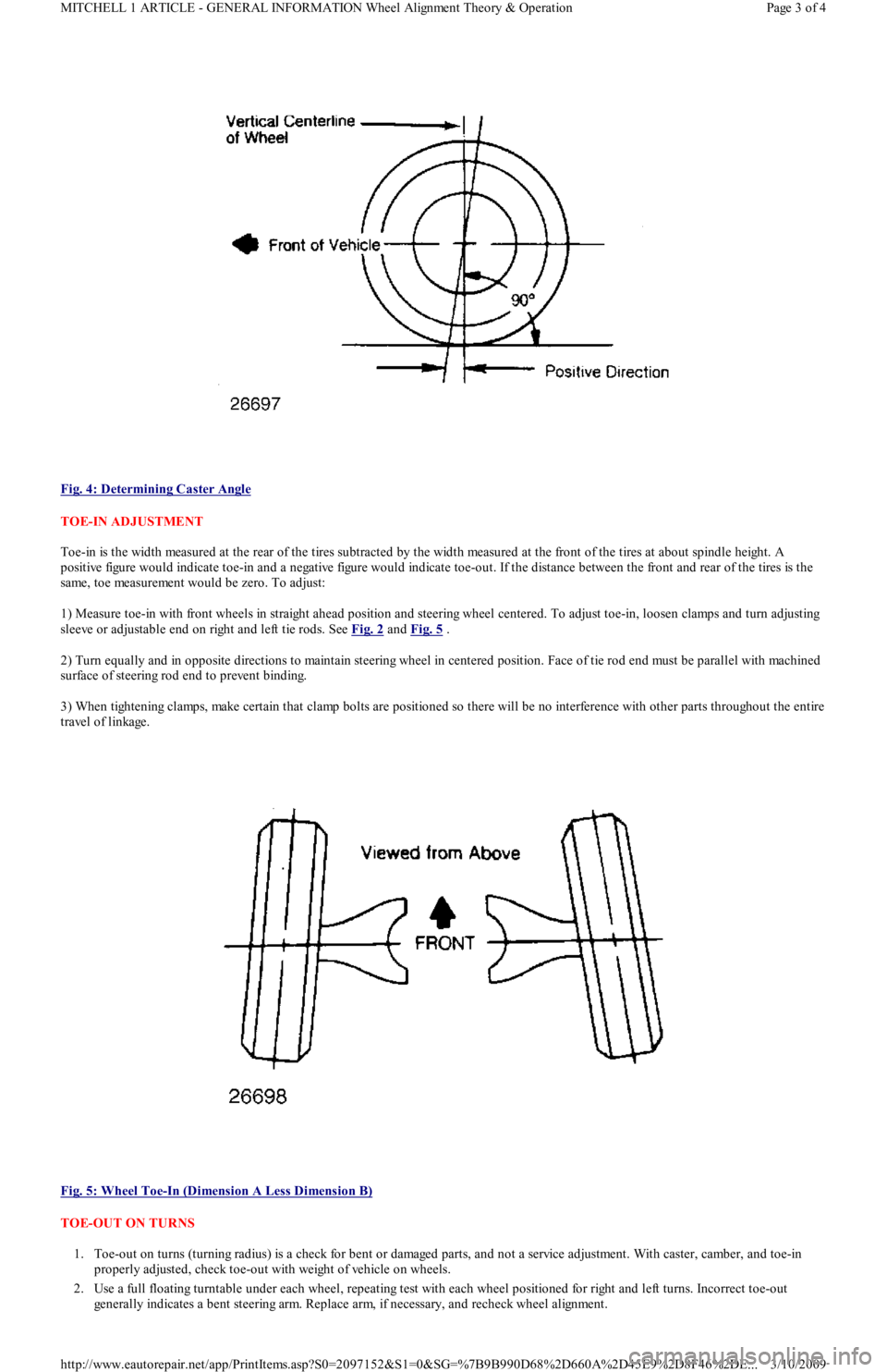
Fig. 4: Determining Caster Angle
TOE-IN ADJUSTMENT
Toe-in is the width measured at the rear of the tires subtracted by the width measured at the front of the tires at about spindle height. A
positive figure would indicate toe-in and a negative figure would indicate toe-out. If the distance between the front and rear of the tires is the
same, toe measurement would be zero. To adjust:
1) Measure toe-in with front wheels in straight ahead position and steering wheel centered. To adjust toe-in, loosen clamps and turn adjusting
sleeve or adjustable end on right and left tie rods. See Fig. 2
and Fig. 5 .
2) Turn equally and in opposite directions to maintain steering wheel in centered position. Face of tie rod end must be parallel with machined
surface of steering rod end to prevent binding.
3) When tightening clamps, make certain that clamp bolts are positioned so there will be no interference with other parts throughout the entire
travel of linkage.
Fig. 5: Wheel Toe
-In (Dimension A Less Dimension B)
TOE-OUT ON TURNS
1. Toe-out on turns (turning radius) is a check for bent or damaged parts, and not a service adjustment. With caster, camber, and toe-in
properly adjusted, check toe-out with weight of vehicle on wheels.
2. Use a full floating turntable under each wheel, repeating test with each wheel positioned for right and left turns. Incorrect toe-out
generally indicates a bent steering arm. Replace arm, if necessary, and recheck wheel alignment.
Page 3 of 4 MITCHELL 1 ARTICLE - GENERAL INFORMATION Wheel Alignment Theory & Operation
3/10/2009 http://www.eautorepair.net/app/PrintItems.asp?S0=2097152&S1=0&SG=%7B9B990D68%2D660A%2D45E9%2D8F46%2DE
...
Page 404 of 454
Back To Article
1983-95 WHEEL ALIGNMENT
Pre-Alignm ent Inspection Procedures
PRE-ALIGNMENT CHECKS
Before making wheel alignment adjustment, perform the following checks:
1. Tires should be equal in size and runout must not be excessive. Tires and wheels should be in balance, and inflated to manufacturer's
specifications.
2. Wheel bearings must be properly adjusted. Steering linkage and suspension must not have excessive looseness. Check for wear in tie rod
ends and ball joints.
3. Steering gear box must not have excessive play. Check and adjust to manufacturer's specifications.
4. Vehicle must be at curb height with full fuel load and spare tire in vehicle. No extra load should be on vehicle.
5. Vehicle must be level with floor and with suspension settled. Jounce front and rear of vehicle several times and allow it to settle to
normal curb height.
6. If steering wheel is not centered with front wheels in straight-ahead position, correct by shortening one tie rod adjusting sleeve and
lengthening opposite sleeve equal amounts.
7. Ensure wheel lug nuts are tightened to torque specifications.
Copyr ight 2009 Mitchell Repair Information Company, LLC. All Rights Reserved.
Article GUID: A00060347
Page 1 of 1 MITCHELL 1 ARTICLE - 1983-95 WHEEL ALIGNMENT Pre-Alignment Inspection Procedures
3/10/2009 http://www.eautorepair.net/app/PrintItems.asp?S0=2097152&S1=0&SG=%7B9B990D68%2D660A%2D45E9%2D8F46%2DE
...
Page 405 of 454
Back To Article
RIDING HEIGHT ADJUSTMENT
1991-92 WHEEL ALIGNMENT Ford Motor Co. - Riding Height Adjustm ent
RIDING HEIGHT ADJUSTMENT
1. Examine vehicle and ensure front or rear end is not higher or lower than normal. Ensure vehicle is level from side to side. Remove any
unusual heavy items before checking suspension.
2. If loading is normal but vehicle is not level, check for spring damage, spring set, or non-standard replacement springs. Repair or replace
as necessary. If in doubt, compare with a new vehicle (if possible).
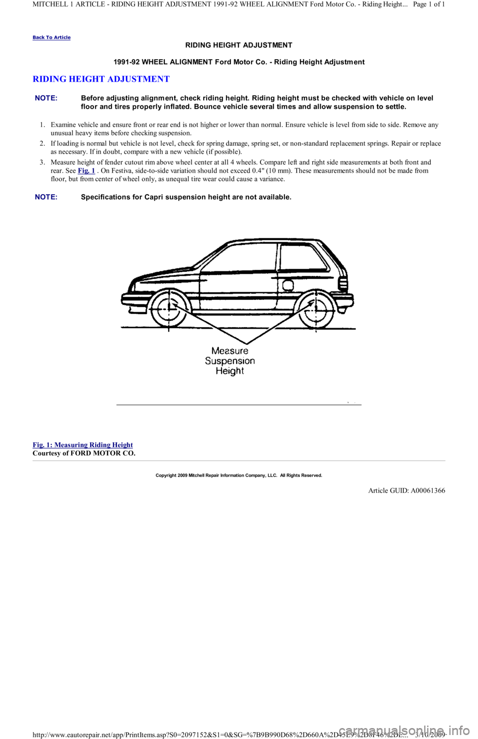
3. Measure height of fender cutout rim above wheel center at all 4 wheels. Compare left and right side measurements at both front and
rear. See Fig. 1
. On Festiva, side-to-side variation should not exceed 0.4" (10 mm). These measurements should not be made from
floor, but from center of wheel only, as unequal tire wear could cause a variance.
Fig. 1: Measuring Riding Height
Courtesy of FORD MOTOR CO. NOTE:Before adjusting alignm ent, check riding height. Riding height m ust be checked with vehicle on level
floor and tires properly inflated. Bounce vehicle several tim es and allow suspension to settle.
NOTE:Specifications for Capri suspension height are not available.
Copyr ight 2009 Mitchell Repair Information Company, LLC. All Rights Reserved.
Article GUID: A00061366
Page 1 of 1 MITCHELL 1 ARTICLE - RIDING HEIGHT ADJUSTMENT 1991-92 WHEEL ALIGNMENT Ford Motor Co. - Riding Height
...
3/10/2009 http://www.eautorepair.net/app/PrintItems.asp?S0=2097152&S1=0&SG=%7B9B990D68%2D660A%2D45E9%2D8F46%2DE
...
Page 406 of 454
Back To Article
WHEEL ALIGNMENT SPECIFICAT IONS & PROCEDURES
1991-92 WHEEL ALIGNMENT Ford Motor Co. - Specifications & Procedures
ADJUSTMENTS
CASTER
Caster is permanently set at factory and is not adjustable. Caster should be checked however as a possible cause of suspension complaint.
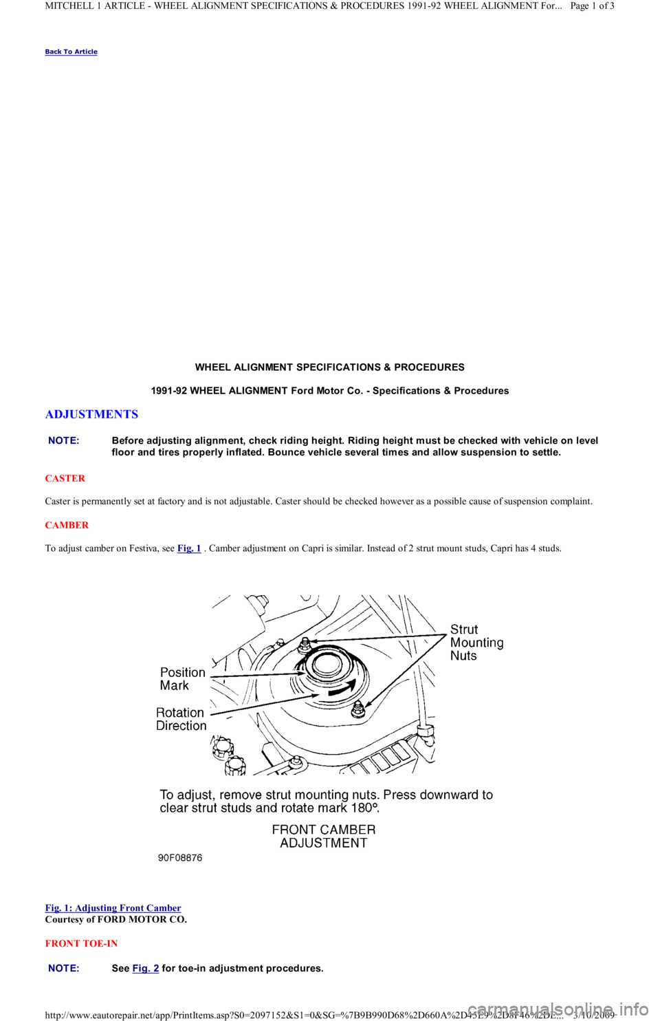
CAMBER
To adjust camber on Festiva, see Fig. 1
. Camber adjustment on Capri is similar. Instead of 2 strut mount studs, Capri has 4 studs.
Fig. 1: Adjusting Front Camber
Courtesy of FORD MOTOR CO.
FRONT TOE-IN NOTE:Before adjusting alignm ent, check riding height. Riding height m ust be checked with vehicle on level
floor and tires properly inflated. Bounce vehicle several tim es and allow suspension to settle.
NOTE:See Fig. 2 for toe-in adjustm ent procedures.
Page 1 of 3 MITCHELL 1 ARTICLE - WHEEL ALIGNMENT SPECIFICATIONS & PROCEDURES 1991-92 WHEEL ALIGNMENT For...
3/10/2009 http://www.eautorepair.net/app/PrintItems.asp?S0=2097152&S1=0&SG=%7B9B990D68%2D660A%2D45E9%2D8F46%2DE
...
Page 441 of 454
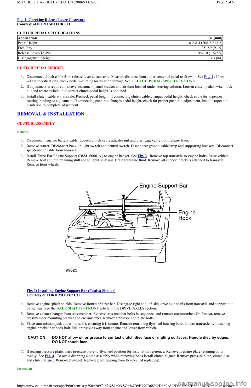
Fig. 2: Checking Release Lever Clearance
Courtesy of FORD MOTOR CO.
CLUTCH PEDAL SPECIFICATIONS
CLUTCH PEDAL HEIGHT
1. Disconnect clutch cable from release lever at transaxle. Measure distance from upper center of pedal to firewall. See Fig. 1
. If not
within specifications, check pedal mounting for wear or damage. See CLUTCH PEDAL SPECIFICATIONS
.
2. If adjustment is required, remove instrument panel bracket and air duct located under steering column. Loosen clutch pedal switch lock
nut and rotate switch until correct clutch pedal height is obtained.
3. Install clutch cable at transaxle. Recheck pedal height. If connecting clutch cable changes pedal height, check cable for improper
routing, binding or adjustment. If connecting push rod changes pedal height, check for proper push rod adjustment. Install carpet and
insulation to complete adjustment.
REMOVAL & INSTALLATION
CLUTCH ASSEMBLY
Removal
1. Disconnect negative battery cable. Loosen clutch cable adjuster nut and disengage cable from release lever.
2. Remove starter. Disconnect back-up light switch and neutral switch. Disconnect ground cable/strap and supporting brackets. Disconnect
speedometer cable from transaxle.
3. Install Three Bar Engine Support (D88L-6000-A ) to engine hanger. See Fig. 3
. Remove top transaxle-to-engine bolts. Raise vehicle.
Remove bolt and nut retaining shift rod to input shift rail. Drain transaxle fluid. Remove all support brackets attached to transaxle.
Remove front wheels.
Fig. 3: Installing Engine Support Bar (Festiva Similar)
Courtesy of FORD MOTOR CO.
4. Remove engine splash shields. Remove front stabilizer bar. Disengage right and left side drive axle shafts from transaxle and support out
of the way. See the AXLE SHAFTS
- FRONT article in the DRIVE AXLES section.
5. Remove exhaust hanger from crossmember. Remove crossmember bolts in sequence, and remove crossmember. On Festiva, remove
crossmember mounting bracket and crossmember. Remove transaxle end plate bolts.
6. Place transmission jack under transaxle, ensuring it is secure. Remove remaining flywheel housing bolts. Lower transaxle by loosening
engine bracket bar hook bolt. Pull transaxle away from engine and lower from vehicle.
7. If reusing pressure plate, mark pressure plate-to-flywheel position for installation reference. Remove pressure plate retaining bolts
evenly. See Fig. 4
. To avoid dropping clutch assembly while removing bolts install clutch aligner. Remove pressure plate, clutch disc
and clutch aligner. Remove flywheel. Remove pilot bearing from flywheel (if replacing).
Inspection
ApplicationIn. (mm)
Pedal Height8.2-8.4 (208.2-213.2)
Free Play.35-.59 (9-15)
Release Lever-To-Pin.06-.10 (1.5-2.5)
Disengagement Height3.3 (84)
CAUT ION: DO NOT allow oil or grease to contact clutch disc face or m ating surfaces. Handle disc by edges.
DO NOT touch face.
Page 2 of 5 MITCHELL 1 ARTICLE - CLUTCH 1988-93 Clutch
3/10/2009 http://www.eautorepair.net/app/PrintItems.asp?S0=2097152&S1=0&SG=%7B9B990D68%2D660A%2D45E9%2D8F46%2DE
...