1991 FORD FESTIVA jump start
[x] Cancel search: jump startPage 4 of 454
Turbo Boost Gauge Always Reads High
If turbo boost gauge always reads high, check these items:
Check for damaged White/Black signal wire.
Check for defective boost sensing unit.
Check for defective boost gauge.
Turbo Boost Gauge Inaccurate
If turbo boost gauge is inaccurate, check these items:
Check for loose or corroded connections.
Check for defective boost sensing unit.
Check for defective boost gauge.
TESTING
FUEL GAUGE SENDING UNIT
Capri
Remove rear seat cushion. Disconnect fuel pump/fuel gauge sending unit electrical connector at access cover. Turn ignition on. Fuel gauge
should read empty. Using a jumper wire, connect Yellow fuel gauge wire of vehicle harness connector to ground. Fuel gauge should read full.
If fuel gauge operates as specified, replace fuel gauge sending unit.
Festiva
Remove fuel gauge sending unit from tank. See FUEL SENDING UNIT under REMOVAL & INSTALLATION. Connect an ohmmeter and
check sending unit resistance as indicated in FUEL GAUGE SENDING UNIT RESISTANCE (FESTIVA)
table. Replace sending unit if
resistance is drastically different than specification.
FUEL GAUGE SENDING UNIT RESISTANCE (FESTIVA)
OIL PRESSURE GAUGE (CAPRI)
1. Remove electrical connector from oil pressure sending unit located on right side of engine block. Turn ignition switch on. Oil pressure
gauge should read low. Install a jumper wire between Yellow/Red wire of oil pressure sending unit vehicle harness connector and
ground. Oil pressure gauge should read high.
2. If oil pressure gauge operates as specified, replace sending unit. If gauge does not operate as specified, check instrument panel power
and ground circuits.
OIL PRESSURE WARNING LIGHT (FESTIVA)
Light Stays On With Engine Running
1. Turn ignition on (DO NOT start engine). Disconnect Yellow/Red wire from oil pressure switch connector. Light should go off.
2. If light stays on, repair short in Yellow/Red wire between oil indicator light and oil pressure switch. Reconnect wire to switch. Light
should be on with ignition on. If light does not go off when engine is started, check switch or engine for low oil pressure.
Oil Light Will Not Go On With Ignition On
1. Ground Yellow/Red wire at instrument panel connector. If light goes on, repair Yellow/Red wire between oil pressure switch and
indicator light or replace defective oil pressure switch.
2. If light does not illuminate, check bulb or check instrument panel ground circuit.
TEMPERATURE GAUGE (CAPRI)
1. Remove electrical connector from temperature sending unit located at front of cylinder head. Connect one lead of Gauge System Tester
(021-00055) to connector and other tester lead to ground. Set tester to 18 ohms, turn ignition switch on and observe temperature gauge.
Gauge should read 250°F.
2. Turn tester to 60 ohms. Gauge should read 175°F. Turn tester to 223 ohms. Gauge should read 100°F. If all readings are within twice
the needle width of correct reading, gauge is functioning properly. If readings are not as specified, replace gauge.
TEMPERATURE GAUGE (FESTIVA)
See TROUBLE SHOOTING for possible service areas.
TEMPERATURE SENDING UNIT (CAPRI)
Remove sending unit from engine and place in container of water. Heat water to 176°F (80°C). Measure resistance between sending unit
connector and case. Resistance should be 49.3-57.7 ohms. If resistance is not as specified, replace sending unit. NOTE:Inspect fuel tank for distortion or dam age. If distorted or dam aged, repair or replace tank before testing.
Float PositionOhms
Full Position (Up)Approximately 7
Half-Full Position (Middle)Approximately 33
Empty Position (Down)Approximately 95
Page 3 of 5 MITCHELL 1 ARTICLE - INSTRUMENT PANEL 1991 ACCESSORIES & SAFETY EQUIPMENT Ford Motor Co. Switches
...
3/10/2009 http://www.eautorepair.net/app/PrintItems.asp?S0=2097152&S1=0&SG=%7B959286D2%2D3A85%2D4BFC%2D9C5C%2D
...
Page 55 of 454
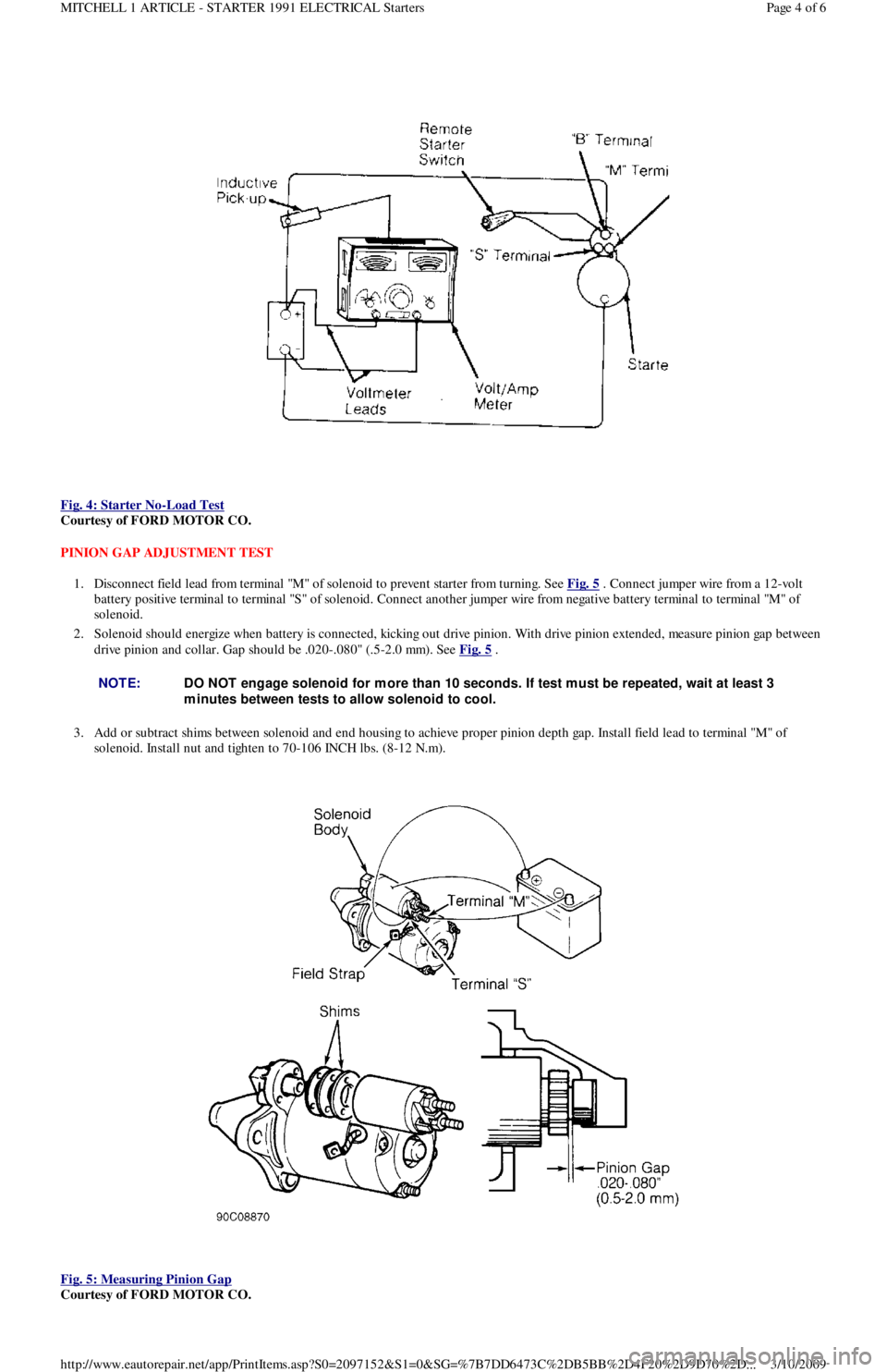
Fig. 4: Starter No
-Load Test
Courtesy of FORD MOTOR CO.
PINION GAP ADJUSTMENT TEST
1. Disconnect field lead from terminal "M" of solenoid to prevent starter from turning. See Fig. 5
. Connect jumper wire from a 12-volt
battery positive terminal to terminal "S" of solenoid. Connect another jumper wire from negative battery terminal to terminal "M" of
solenoid.
2. Solenoid should energize when battery is connected, kicking out drive pinion. With drive pinion extended, measure pinion gap between
drive pinion and collar. Gap should be .020-.080" (.5-2.0 mm). See Fig. 5
.
3. Add or subtract shims between solenoid and end housing to achieve proper pinion depth gap. Install field lead to terminal "M" of
solenoid. Install nut and tighten to 70-106 INCH lbs. (8-12 N.m).
Fig. 5: Measuring Pinion Gap
Courtesy of FORD MOTOR CO.
NOTE:DO NOT engage solenoid for m ore than 10 seconds. If test m ust be repeated, wait at least 3
m inutes between tests to allow solenoid to cool.
Page 4 of 6 MITCHELL 1 ARTICLE - STARTER 1991 ELECTRICAL Starters
3/10/2009 http://www.eautorepair.net/app/PrintItems.asp?S0=2097152&S1=0&SG=%7B7DD6473C%2DB5BB%2D4F20%2D9D70%2D
...
Page 106 of 454

article. Install timing belt and covers. Install cam cover. On non-turbo engines, connect front exhaust pipe to exhaust manifold. Tighten
nuts to specification.
4. On turbocharged engines, install exhaust manifold and turbocharger assembly. Install ground wire and strap to cylinder head with
retaining bolts. Connect intercooler tubes (if equipped). Connect O2 sensor connector, and install ground wires to bracket on cylinder
head with retaining screw. Connect main engine harness connector. Connect fuel lines to fuel filter and pressure regulator. Install
throttle cable and retaining brackets.
5. Install coolant hoses and vacuum lines to intake manifold and throttle body. Install coolant hose to thermostat cover. Install intake air
tube to air cleaner. Install spark plug wires and retainers. Install intake air tube to throttle body, and connect by-pass hoses. Fill cooling
system. Connect negative battery terminal. Start engine, check for leaks and system operation.
TIMING BELT COVER
Removal & Installation (1.3L)
Remove accessory belts. Remove water pump pulley. Remove crankshaft damper. Remove bolts retaining upper and lower cover halves to
engine front. Remove both covers. To install, reverse removal procedure.
Removal & Installation (1.6L)
Raise vehicle on hoist. Remove RF tire and wheel assembly. Remove RF splash guard. Lower vehicle. Remove spark plugs and set camsh aft
timing to TDC No. 1 cylinder. Remove oil dipstick. Remove water pump pulley. Remove crankshaft pulley, damper and baffle plate. Remove
upper timing belt cover. Remove center and lower timing belt covers. To install, reverse removal procedure.
TIMING BELT
Removal (1.3L)
Remove accessory belts, water pump pulley, crankshaft damper and upper and lower timing belt covers. Mark timing belt direction of rotation
for installation reference. Remove timing belt tensioner pulley bolt. Remove tensioner pulley, spring and spring cover. Remove timing belt.
Installation (1.3L)
1. Ensure timing belt and sprockets are clean and not worn or damaged. Align crankshaft and camshaft timing marks. See Fig. 3 . No. 1
cylinder must be at TDC of compression stroke.
2. Position belt on camshaft sprocket. Install timing belt tensioner spring, spring cover and pulley. Tighten tensioner pulley bolt to
specification. See TORQUE SPECIFICATIONS
table at end of article. To complete installation, reverse removal procedure. Tighten
all bolts and nuts to specification.
Fig. 3: Aligning Camshaft & Crankshaft Timing Marks (1.3L)
Courtesy of FORD MOTOR CO.
Removal (1.6L)
NOTE:Always rotate engine in direction of norm al operation. Rotating crankshaft backwards m ay cause belt to
jump timing.
Page 6 of 19 MITCHELL 1 ARTICLE - ENGINE OVERHAUL 1991-92 FORD MOTOR CO. ENGINES 1.3L & 1.6L 4-Cylinder
3/10/2009 http://www.eautorepair.net/app/PrintItems.asp?S0=2097152&S1=0&SG=%7B959286D2%2D3A85%2D4BFC%2D9C5C%2D
...
Page 123 of 454
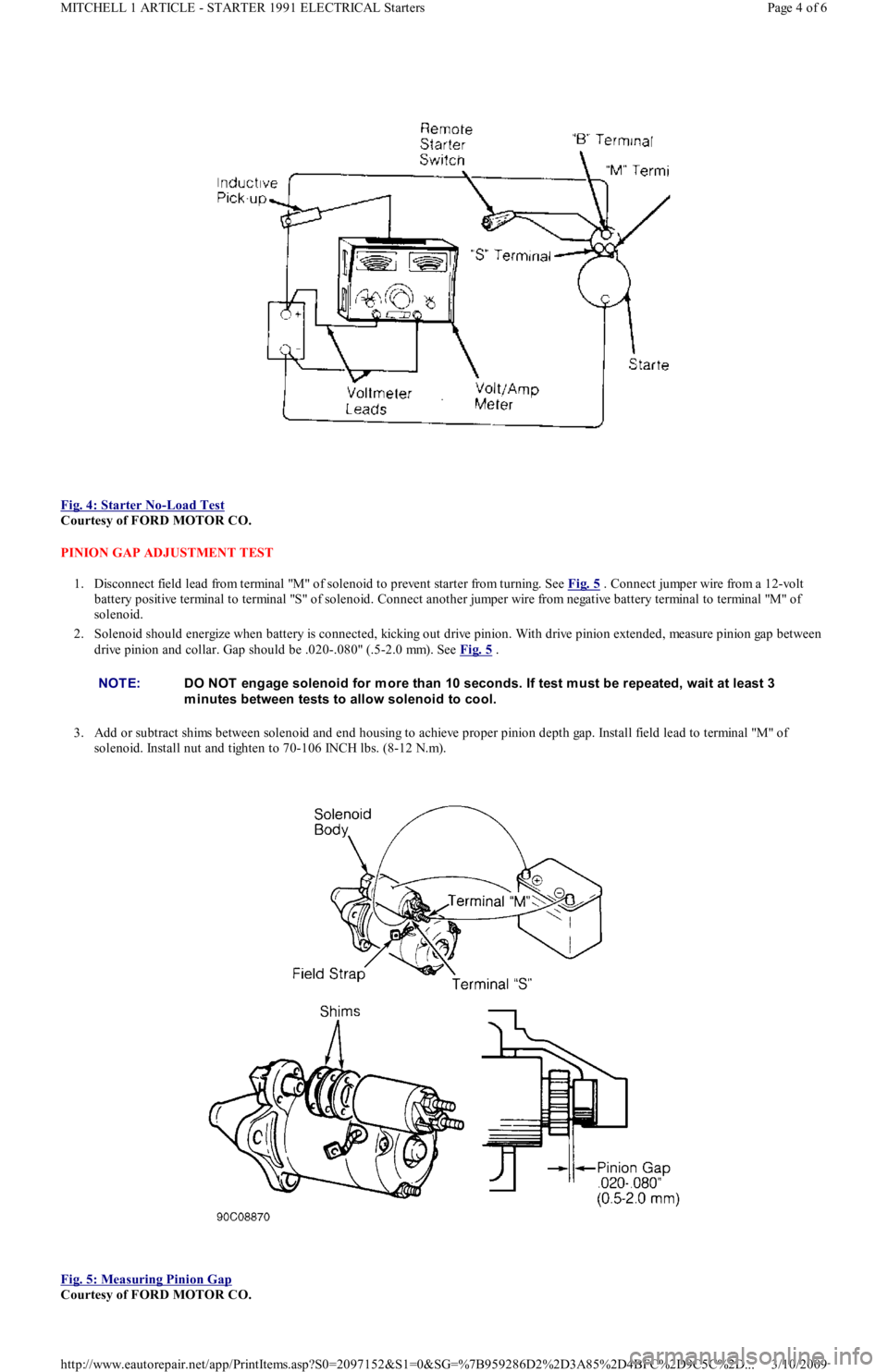
Fig. 4: Starter No
-Load Test
Courtesy of FORD MOTOR CO.
PINION GAP ADJUSTMENT TEST
1. Disconnect field lead from terminal "M" of solenoid to prevent starter from turning. See Fig. 5
. Connect jumper wire from a 12-volt
battery positive terminal to terminal "S" of solenoid. Connect another jumper wire from negative battery terminal to terminal "M" of
solenoid.
2. Solenoid should energize when battery is connected, kicking out drive pinion. With drive pinion extended, measure pinion gap between
drive pinion and collar. Gap should be .020-.080" (.5-2.0 mm). See Fig. 5
.
3. Add or subtract shims between solenoid and end housing to achieve proper pinion depth gap. Install field lead to terminal "M" of
solenoid. Install nut and tighten to 70-106 INCH lbs. (8-12 N.m).
Fig. 5: Measuring Pinion Gap
Courtesy of FORD MOTOR CO.
NOTE:DO NOT engage solenoid for m ore than 10 seconds. If test m ust be repeated, wait at least 3
m inutes between tests to allow solenoid to cool.
Page 4 of 6 MITCHELL 1 ARTICLE - STARTER 1991 ELECTRICAL Starters
3/10/2009 http://www.eautorepair.net/app/PrintItems.asp?S0=2097152&S1=0&SG=%7B959286D2%2D3A85%2D4BFC%2D9C5C%2D
...
Page 129 of 454
Back To Article
D - ADJUSTMENTS
1991 ENGINE PERFORMANCE Ford/Mercury - On-Vehicle Adjustm ents
ADJUSTMENTS
ENGINE MECHANICAL
Before beginning any on-vehicle adjustments to fuel or ignition systems, ensure engine mechanical condition is okay.
VALVE CLEARANCE
IGNITION TIMING
CAPRI
1. Place automatic transmission in Park or manual transmission in Neutral. Disconnect and plug hoses attached to vacuum diaphragm
assembly on distributor. Connect tachometer and timing light. Turn off all electrical loads.
2. Start engine, and warm it to operating temperature. Ensure idle speed is set to specification, adjusting if necessary. See IDLE SPEED &
MIXTURE . Determine initial timing. See IGNITION TIMING table. If base timing is not correct, loosen distributor mounting bolts
and rotate distributor until marks align. Tighten bolts to 14-18 ft. lbs. (19-25 N.m).
3. Increase engine RPM while observing timing light. Verify ignition timing advances. For Turbo models, go to step 5). For non-Turbo
models, continue with step 4).
4. On non-Turbo models, apply 16 in. Hg vacuum to chamber "A". Verify timing advances by 26-30 degrees. Remove vacuum source from
chamber "A". Apply 8 in. Hg vacuum to chamber "B" while observing timing. Verify timing advances by 3-7 degrees. Stop engine, and
remove test equipment.
5. On Turbo models, apply 20 in. Hg vacuum to advance diaphragm. Verify timing advances by 13-17 degrees. Disconnect vacuum source.
Apply 8 psi (.6 kg/cm
2 ) pressure to advance diaphragm. Verify timing retards by 3-7 degrees. Stop engine, and remove test equipment.
FESTIVA
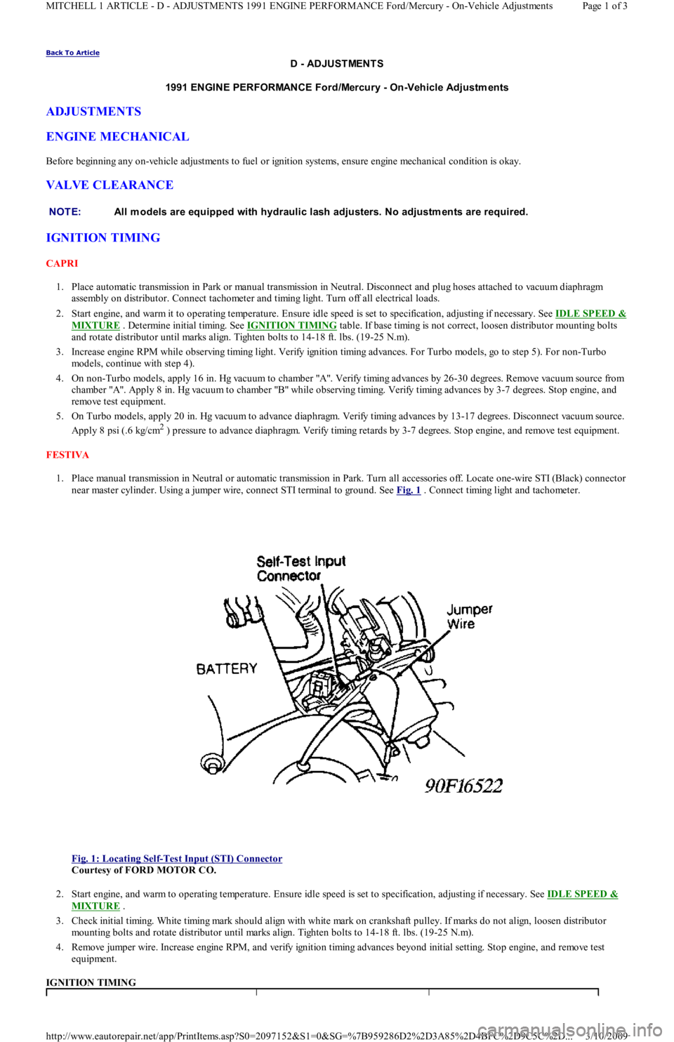
1. Place manual transmission in Neutral or automatic transmission in Park. Turn all accessories off. Locate one-wire STI (Black) connector
near master cylinder. Using a jumper wire, connect STI terminal to ground. See Fig. 1
. Connect timing light and tachometer.
Fig. 1: Locating Self
-Test Input (STI) Connector
Courtesy of FORD MOTOR CO.
2. Start engine, and warm to operating temperature. Ensure idle speed is set to specification, adjusting if necessary. See IDLE SPEED &
MIXTURE .
3. Check initial timing. White timing mark should align with white mark on crankshaft pulley. If marks do not align, loosen distributor
mounting bolts and rotate distributor until marks align. Tighten bolts to 14-18 ft. lbs. (19-25 N.m).
4. Remove jumper wire. Increase engine RPM, and verify ignition timing advances beyond initial setting. Stop engine, and remove test
equipment.
IGNITION TIMING NOTE:All m odels are equipped with hydraulic lash adjusters. No adjustm ents are required.
Page 1 of 3 MITCHELL 1 ARTICLE - D - ADJUSTMENTS 1991 ENGINE PERFORMANCE Ford/Mercury - On-Vehicle Adjustments
3/10/2009 http://www.eautorepair.net/app/PrintItems.asp?S0=2097152&S1=0&SG=%7B959286D2%2D3A85%2D4BFC%2D9C5C%2D
...
Page 156 of 454

Back To Article
F - BASIC TESTING
1991-92 ENGINE PERFORMANCE Ford Motor Co. Basic Diagnostic Procedures
INTRODUCTION
The following diagnostic steps help prevent overlooking simple problems and begin diagnosis for a no-start condition.
The first step in diagnosing any driveability problem is to verify the complaint. Test drive the vehicle under the conditions in which the
problem reportedly occurred.
Before entering self-diagnostics, perform a careful and complete visual inspection. Most engine control problems result from mechanical
breakdowns, poor electrical connections or damaged/misrouted vacuum hoses. Before condemning the computerized system, perform each test
listed in this article.
PRELIMINARY INSPECTION & ADJUSTMENTS
VISUAL INSPECTION
Perform a visual inspection of all electrical wiring. Look for chafed, stretched, cut or pinched wiring. Ensure electrical connections fit tightly
and are not corroded. Ensure vacuum hoses are properly routed and are not cut or pinched. If necessary, see VACUUM DIAGRAMS article in
the ENGINE PERFORMANCE Section to verify routing and connections. Inspect air induction system for possible vacuum leaks.
MECHANICAL INSPECTION
Compression
Engine mechanical condition can be checked using a compression gauge, vacuum gauge or engine analyzer. See engine analyzer instruction
manual for specific instructions. Lowest compression reading must be not less than 75 percent of highest reading.
Exhaust System Backpressure
Exhaust system can be checked with a vacuum gauge or a 0-5 psi pressure gauge. If a pressure gauge is used, remove O2 sensor. Connect gauge
to O2 sensor port. Start engine, and run at 2500 RPM. If exhaust system backpressure is more than 2 psi, exhaust system or catalytic converter
is plugged.
If a vacuum gauge is used, connect it to intake manifold vacuum. Start engine. Observe vacuum gauge. Open throttle part way and hold steady.
If vacuum gauge drops slowly after stabilizing, check exhaust system for a restriction.
FUEL PRESSURE
Fuel Pressure Release
Start engine (if possible), and unplug VAF meter connector. When engine stalls, turn ignition off and reconnect VAF meter wiring. Usin g sh o p
towel, cover fitting to absorb leakage when opening fuel system.
Fuel Pressure Check
1. Connect fuel pressure gauge between fuel filter and fuel rail. Open main valve, and close drain valve. Locate fuel pump check connector
in engine compartment, near left strut. Connect jumper wire between fuel pump test terminals (Black and Green/White wires on Capri
or Black and Green/Red wires on Festiva).
2. Turn ignition on to activate fuel pump. If pump does not run, check fuel pump circuit. If possible, start engine. Measure and record fuel
pressure. For fuel pressure specifications, see FUEL PRESSURE SPECIFICATIONS
article. Disconnect vacuum from pressure
regulator. Turn engine off. Wait 5 minutes and ensure residual pressure is at least 21 psi (1.5 kg/cm
2 ).
3. Operate fuel pump by reconnecting jumper wire at fuel pump check connector. Check fuel pump performance. Pinch hose between
pressure gauge and fuel filter. Do not hold longer than necessary to check pressure.For fuel pressure specifications, see FUEL
PRESSURE SPECIFICATIONS article. If pump does not meet specifications, check fuel pump circuit, fuel pump, fuel tank and fuel
filter or replace fuel pump.
FUEL PUMP PERFORMANCE NOTE:Unless stated otherwise in test procedure, perform all voltage tests with a Digital Volt-Ohm m eter
(DVOM) with a m inim um 10-m egohm input im pedance.
CAUT ION: DO NOT use ignition switch during com pression tests on fuel injected vehicles. Fuel injectors are
triggered by ignition switch during cranking m ode. Use a rem ote starter to crank engine to prevent fire
hazard and catalytic converter and engine oiling system contam ination.
WARNING:ALWAYS relieve fuel pressure before disconnecting any fuel injection system com ponent. DO NOT
allow fuel to contact engine or electrical com ponents.
NOTE:For 1991 fuel pressure specifications, see FUEL PRESSURE SPECIFICAT IONS
article. For 1992 fuel
pressure specifications, see FUEL PRESSURE SPECIFICAT IONS
article.
ApplicationPressure psi (kg/cm2 )Min. Vol. in 10 sec. Ozs. (cc)
Capri(1) 5.5 (167)
Festiva(1) 7.4 (220)
Page 1 of 4 MITCHELL 1 ARTICLE - F - BASIC TESTING 1991-92 ENGINE PERFORMANCE Ford Motor Co. Basic Diagnostic Proced
...
3/10/2009 http://www.eautorepair.net/app/PrintItems.asp?S0=2097152&S1=0&SG=%7B959286D2%2D3A85%2D4BFC%2D9C5C%2D
...
Page 169 of 454

memory. Intermittent failures may be caused by a sensor, connector, or wiring. See INTERMITTENTS in TESTS W/O CODES article in the
ENGINE PERFORMANCE Section.
VISUAL CHECK & VEHICLE PREPARATION
Before connecting any equipment to diagnose EEC system, perform following preparatory procedures:
Verify condition of air cleaner and air ducts.
Check all vacuum hoses for leaks, restrictions, or improper routing.
Check EEC system wiring harness electrical connections for corrosion, bent or broken pins, loose wires or terminals, or improper
routing.
Check ECA, sensors, and actuators for physical damage.
Check engine oil and coolant level.
Perform all necessary safety precautions to prevent personal injury or vehicle damage.
Set parking brake. Place shift lever in Park for automatic transmissions, or Neutral for manual transmissions. DO NOT move shift lever
during test unless specifically directed.
Turn off all lights and accessories. Ensure vehicle doors are closed when measuring voltage or resistance.
Start engine. Run at idle until upper radiator hose is hot and pressurized and engine is off fast idle. Check for leaks around exhaust
manifold, exhaust gas oxygen sensor, and vacuum hose connections.
Turn ignition off. Service items as required. Go to EQUIPMENT HOOK-UP .
EQUIPMENT HOOK-UP
VOM
1. Turn ignition off. Connect a jumper wire from STI connector to ground. Refer to SELF-TEST CONNECTOR LOCATION and
SELF
-TEST CONNECTOR WIRE COLORS tables. See Fig. 1 .
2. Connect VOM between STO terminal and engine ground. Set VOM to measure 0-20 volts DC.
CHECK ENGINE Light (MIL)
Connect a jumper wire between STI connector and ground.
SUPER STAR II Tester
Turn ignition off. Connect adapter cable leads to diagnostic tester. Connect service adapter cables to vehicle self-test connectors. Ground
adapter cable.
SELF-TEST CONNECTOR LOCATION
SELF-TEST CONNECTOR WIRE COLORS
Fig. 1: Self
-Test Connector Terminal ID
Courtesy of FORD MOTOR CO.
RETRIEVING CODES
Reading Service Codes
ApplicationLocation
1.3LLeft Rear Corner Of Engine Compartment
1.6LRight Rear Corner Of Engine Compartment
CircuitWire Color
1.3L
SMLBlue/Green
STIYellow/Green
STOYellow/White
1.6L
SMLBlack/Blue
STIYellow
STOGreen/Black
Page 2 of 20 MITCHELL 1 ARTICLE - G - TESTS W/CODES 1991-92 ENGINE PERFORMANCE Ford Motor Co. Self-Diagnostics
3/10/2009 http://www.eautorepair.net/app/PrintItems.asp?S0=2097152&S1=0&SG=%7B7DD6473C%2DB5BB%2D4F20%2D9D70%2D
...
Page 283 of 454
Circuits with external injector resistors. Used predominately on some Asian & European systems, they are used to reduce the available
voltage to an injector in order to limit the current flow. This lower voltage can cause a dim flash on a noid light designed for full voltage.
Circuits with current controlled injector drivers (e.g. "Peak and Hold"). Basically, this type of driver allows a quick burst of
voltage/current to flow and then throttles it back significantly for the remainder of the pulse width duration. If a noid light was designed
for the other type of driver (voltage controlled, e.g. "Saturated"), it will appear dim because it is expecting full voltage/current to flow
for the entire duration of the pulse width.
Let's move to the other situation where a noid light flashes normally when it should be dim. This could occur if a more sensitive n o id l igh t is
used on a higher voltage/amperage circuit that was weakened enough to cause problems (but not outright broken). A circuit with an actual
problem would thus appear normal.
Let's look at why. A noid light does not come close to consuming as much amperage as an injector solenoid. If there is a partial driver failure
or a minor voltage drop in the injector circuit, there can be adequate amperage to fully operate the noid light BUT NOT ENOUGH TO
OPERATE THE INJECTOR.
If this is not clear, picture a battery with a lot of corrosion on the terminals. Say there is enough corrosion that the starter motor will not
operate; it only clicks. Now imagine turning on the headlights (with the ignition in the RUN position). You find they light normally and are
fully bright. This is the same idea as noid light: There is a problem, but enough amp flow exists to operate the headlights ("noid light"), but not
the starter motor ("injector").
How do you identify and avoid all these situations? By using the correct type of noid light. This requires that you understanding the types of
injector circuits that your noid lights are designed for. There are three. They are:
Systems with a voltage controlled injector driver. Another way to say it: The noid light is designed for a circuit with a "high" resistance
injector (generally 12 ohms or above).
Systems with a current controlled injector driver. Another way to say it: The noid light is designed for a circuit with a low resistance
injector (generally less than 12 ohms) without an external injector resistor.
Systems with a voltage controlled injector driver and an external injector resistor. Another way of saying it: The noid light is designed
for a circuit with a low resistance injector (generally less than 12 ohms) and an external injector resistor.
If you are not sure which type of circuit your noid light is designed for, plug it into a known good car and check out the results. If it flashes
normally during cranking, determine the circuit type by finding out injector resistance and if an external injector resistor is used. You now
know enough to identify the type of injector circuit. Label the noid light appropriately.
Next time you need to use a noid light for diagnosis, determine what type of injector circuit you are dealing with and select the appropriate
noid light.
Of course, if you suspect a no-pulse condition you could plug in any one whose connector fit without fear of misdiagnosis. This is because it is
unimportant if the flashing light is dim or bright. It is only important that it flashes.
In any cases of doubt regarding the use of a noid light, a lab scope will overcome all inherent weaknesses.
OVERVIEW OF DVOM
A DVOM is typically used to check injector resistance and available voltage at the injector. Some techs also use it check injector on-time
either with a built-in feature or by using the dwell/duty function.
There are situations where the DVOM performs these checks dependably, and other situations where it can deceive you. It is important to be
aware of these strengths and weaknesses. We will cover the topics above in the following text.
Checking Injector Resistance
If a short in an injector coil winding is constant, an ohmmeter will accurately identify the lower resistance. The same is true with an open
winding. Unfortunately, an intermittent short is an exception. A faulty injector with an intermittent short will show "good" if the ohmmeter
cannot force the short to occur during testing.
Alcohol in fuel typically causes an intermittent short, happening only when the injector coil is hot and loaded by a current high e n o u gh t o
jump the air gap between two bare windings or to break down any oxides that may have formed between them.
When you measure resistance with an ohmmeter, you are only applying a small current of a few milliamps. This is nowhere near enough to
load the coil sufficiently to detect most problems. As a result, most resistance checks identify intermittently shorted injectors as being normal.
There are two methods to get around this limitation. The first is to purchase an tool that checks injector coil windings under full load. The
Kent-Moore J-39021 is such a tool, though there are others. The Kent-Moore costs around $240 at the time of this writing and works on many
different manufacturer's systems.
The second method is to use a lab scope. Remember, a lab scope allows you to see the regular operation of a circuit in real time. If an injector
is having an short or intermittent short, the lab scope will show it.
Checking Available Voltage At the Injector
Verifying a fuel injector has the proper voltage to operate correctly is good diagnostic technique. Finding an open circuit on the feed circuit
like a broken wire or connector is an accurate check with a DVOM. Unfortunately, finding an intermittent or excessive resistance problem with
a DVOM is unreliable.
Let's explore this drawback. Remember that a voltage drop due to excessive resistance will only occur when a circuit is operating? Since the
injector circuit is only operating for a few milliseconds at a time, a DVOM will only see a potential fault for a few milliseconds. The remaining
90+% of the time the unloaded injector circuit will show normal battery voltage. NOTE:Som e noid lights can m eet both the second and third categories sim ultaneously.
Page 2 of 19 MITCHELL 1 ARTICLE - GENERAL INFORMATION Waveforms - Injector Pattern Tutorial
3/10/2009 http://www.eautorepair.net/app/PrintItems.asp?S0=2097152&S1=0&SG=%7B9B990D68%2D660A%2D45E9%2D8F46%2DE
...