1991 FORD FESTIVA reset
[x] Cancel search: resetPage 29 of 454
Power brake push rod length is not adjustable.
Festiva
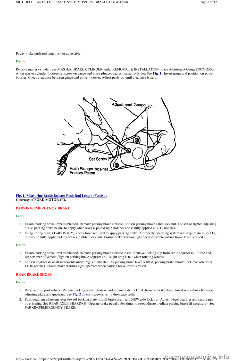
Remove master cylinder. See MASTER BRAKE CYLINDER under REMOVAL & INSTALLATION. Place Adjustment Gauge (T87C-2500-
A) on master cylinder. Loosen set screw on gauge and place plunger against master cylinder. See Fig. 1
. Invert gauge and position on power
booster. Check clearance between gauge and power booster. Adjust push rod until clearance is zero.
Fig. 1: Measuring Brake Booster Push Rod Length (Festiva)
Courtesy of FORD MOTOR CO.
PARKING/EMERGENCY BRAKE
Capri
1. Ensure parking brake lever is released. Remove parking brake console. Loosen parking brake cable lock nut. Loosen or tighten adjusting
nut so parking brake begins to apply when lever is pulled up 5 notches and is fully applied at 7-11 notches.
2. Using Spring Scale (T74P-3504-Y), check force required to apply parking brake. A properly operating system will require 44 lb. (97 kg)
of force to fully apply parking brakes. Tighten lock nut. Ensure brake warning light operates when parking brake lever is raised.
Festiva
1. Ensure parking brake lever is released. Remove parking brake console insert. Remove locking clip from cable adjuster nut. Raise and
support rear of vehicle. Tighten parking brake adjuster until slight drag is felt when rotating wheels.
2. Loosen adjuster in small increments until drag is eliminated. As parking brake lever is lifted, parking brake should lock rear wheels in
11-16 notches. Ensure brake warning light operates when parking brake lever is raised.
REAR BRAKE SHOES
Festiva
1. Raise and support vehicle. Release parking brake. Unstake and remove axle lock nut. Remove brake drum. Insert screwdriver between
adjusting plate and quadrant. See Fig. 2
. Twist screwdriver to disengage teeth.
2. Push quadrant adjusting lever toward backing plate. Install brake drum and NEW axle lock nut. Adjust wheel bearings and secure nut
by crimping. See REAR AXLE BEARINGS. Operate brake pedal a few times to reset adjuster. Adjust parking brake (if necessary). See
PARKING/EMERGENCY BRAKE.
Page 2 of 12 MITCHELL 1 ARTICLE - BRAKE SYSTEM 1991-92 BRAKES Disc & Drum
3/10/2009 http://www.eautorepair.net/app/PrintItems.asp?S0=2097152&S1=0&SG=%7B7DD6473C%2DB5BB%2D4F20%2D9D70%2D
...
Page 51 of 454
CATALYTIC CONVERTER
Continued operation of vehicle with a severe malfunction could cause converter to overheat, resulting in possible damage to converter and
ve h ic l e .
Any modification to the exhaust system on turbo models, which reduces exhaust backpressure, will lead to lean fuel mixtures and excessive
spark advance. This could cause serious engine damage.
ELECTROSTATIC DISCHARGE SENSITIVE (ESD) PARTS
ENGINE OIL
FUEL PUMP SHUTOFF SWITCH
This switch stops flow of fuel to engine after a collision. The impact does not have to be great for switch to be triggered. Switch must be reset
after collision. Switch is located under left rear speaker in luggage compartment. Press button to reset switch.
FUEL SYSTEM SERVICE
HALOGEN BULBS
PASSIVE RESTRAINTS
RADIATOR CAP
RADIATOR FAN WARNING:Many solid state electrical com ponents can be dam aged by static electricity (ESD). Som e will display a
warning label, but m any will not. Discharge personal static electricity by touching a m etal ground point
on the vehicle prior to servicing any ESD sensitive com ponent.
CAUT ION: Never use non-detergent or straight m ineral oil.
WARNING:Relieve fuel system pressure prior to servicing any fuel system com ponent (fuel injection m odels).
WARNING:Halogen bulbs contain pressurized gas which m ay explode if overheated. DO NOT touch glass portion
of bulb with bare hands. Eye protection should be worn when handling or working around halogen
bulbs.
CAUT ION: Before operating vehicle, securely fasten passive shoulder restraints to the em ergency release buckles.
T he buckle fits in only one way. Ensure to position it properly.
CAUT ION: Always disconnect the fan m otor when working near the radiator fan. T he fan is tem perature controlled
and could start at any tim e even when the ignition key is in the OFF position. DO NOT loosen or rem ove
radiator cap when cooling system is hot.
WARNING:Keep hands away from radiator fan. Fan is controlled by a therm ostatic switch which m ay com e on or
run for up to 15 m inutes even after engine is turned off.
Copyr ight 2009 Mitchell Repair Information Company, LLC. All Rights Reserved.
Article GUID: A00058075
Page 3 of 3 MITCHELL 1 ARTICLE - FUSES & CIRCUIT BREAKERS Fuses & Circuit Breakers 1988-93 Festiva
3/10/2009 http://www.eautorepair.net/app/PrintItems.asp?S0=2097152&S1=0&SG=%7B7DD6473C%2DB5BB%2D4F20%2D9D70%2D
...
Page 107 of 454
Remove timing belt covers, See TIMING BELT COVER procedure to remove timing belt from this engine.
Installation (1.6L)
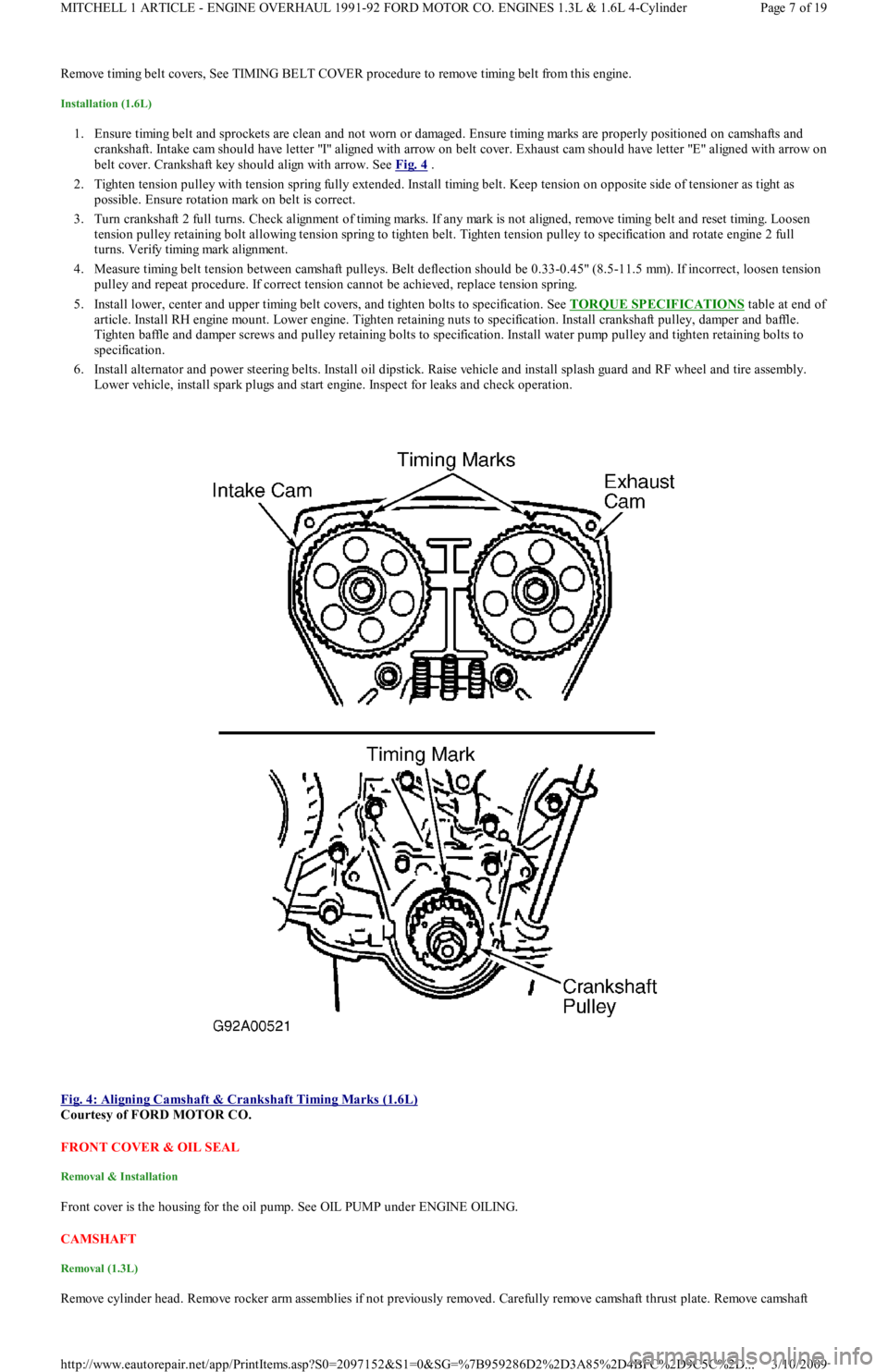
1. Ensure timing belt and sprockets are clean and not worn or damaged. Ensure timing marks are properly positioned on camshafts and
crankshaft. Intake cam should have letter "I" aligned with arrow on belt cover. Exhaust cam should have letter "E" aligned with arrow on
belt cover. Crankshaft key should align with arrow. See Fig. 4
.
2. Tighten tension pulley with tension spring fully extended. Install timing belt. Keep tension on opposite side of tensioner as tight as
possible. Ensure rotation mark on belt is correct.
3. Turn crankshaft 2 full turns. Check alignment of timing marks. If any mark is not aligned, remove timing belt and reset timing. Lo o se n
tension pulley retaining bolt allowing tension spring to tighten belt. Tighten tension pulley to specification and rotate engine 2 full
turns. Verify timing mark alignment.
4. Measure timing belt tension between camshaft pulleys. Belt deflection should be 0.33-0.45" (8.5-11.5 mm). If incorrect, loosen tension
pulley and repeat procedure. If correct tension cannot be achieved, replace tension spring.
5. Install lower, center and upper timing belt covers, and tighten bolts to specification. See TORQUE SPECIFICATIONS
table at end of
article. Install RH engine mount. Lower engine. Tighten retaining nuts to specification. Install crankshaft pulley, damper and baffle.
Tighten baffle and damper screws and pulley retaining bolts to specification. Install water pump pulley and tighten retaining bolts to
specification.
6. Install alternator and power steering belts. Install oil dipstick. Raise vehicle and install splash guard and RF wheel and tire assembly.
Lower vehicle, install spark plugs and start engine. Inspect for leaks and check operation.
Fig. 4: Aligning Camshaft & Crankshaft Timing Marks (1.6L)
Courtesy of FORD MOTOR CO.
FRONT COVER & OIL SEAL
Removal & Installation
Front cover is the housing for the oil pump. See OIL PUMP under ENGINE OILING.
CAMSHAFT
Removal (1.3L)
Remove cylinder head. Remove rocker arm assemblies if not previously removed. Carefully remove camshaft thrust plate. Remove camsh aft
Page 7 of 19 MITCHELL 1 ARTICLE - ENGINE OVERHAUL 1991-92 FORD MOTOR CO. ENGINES 1.3L & 1.6L 4-Cylinder
3/10/2009 http://www.eautorepair.net/app/PrintItems.asp?S0=2097152&S1=0&SG=%7B959286D2%2D3A85%2D4BFC%2D9C5C%2D
...
Page 130 of 454

IDLE SPEED & MIXTURE
IDLE MIXTURE
IDLE SPEED
1. Turn off all accessories. Place automatic transmission in Park or manual transmission in Neutral. Set parking brake. Connect tachometer
to engine. Warm engine to normal operating temperature. Connect a jumper wire between single-wire STI test connector (Green on
Capri; Black on Festiva) and ground. See Fig. 1
.
2. Locate idle speed control by-pass air (ISC-BPA) valve on intake manifold. Remove cap, and adjust idle speed to specification by turning
idle air adjust screw on ISC-BPA valve. See Fig. 2
. Remove jumper wire.
IDLE RPM
Fig. 2: Locating Idle Air Adjust Screw
Courtesy of FORD MOTOR CO.
THROTTLE POSITION SWITCH (TP)
CAPRI
Throttle position sensor is preset at factory. No adjustment is required.
FESTIVA
1. Ensure idle speed and ignition timing are adjusted to specification. Stop engine. Disconnect negative battery cable.
2. Unplug TP connector at throttle body. Insert appropriate feeler gauge between throttle stop screw and stop lever. Check for continuity
between specified terminals on TP connector. See TP ADJUSTMENT table.
3. To adjust, loosen TP attaching screws. Connect ohmmeter between terminals IDL and TL. See Fig. 3
. Insert a .020" (.5 mm) feeler
gauge between throttle stop screw and stop lever.
4. Rotate TP until ohmmeter indicates continuity. Insert a .028" (.7 mm) thickness gauge between stop screw and stop lever. Ohmmeter
should indicate no continuity. If ohmmeter indicates continuity, repeat adjustment procedure.
ApplicationAuto. Trans.Man. Trans.
1.3L9-11 @ 8509-11 @ 700
1.6L Non-Turbo1-3 @ 8500-4 @ 850
1.6L Turbo10-14 @ 8500-4 @ 850
NOTE:Idle m ixture is controlled by ECA and is not adjustable.
ApplicationAuto. Trans.Man. Trans.
1.3L830-870680-720
1.6L800-900800-900
CAUT ION: DO NOT tam per with throttle stop screw at throttle lever. Doing so m ay result in dam age to throttle
body.
Page 2 of 3 MITCHELL 1 ARTICLE - D - ADJUSTMENTS 1991 ENGINE PERFORMANCE Ford/Mercury - On-Vehicle Adjustments
3/10/2009 http://www.eautorepair.net/app/PrintItems.asp?S0=2097152&S1=0&SG=%7B959286D2%2D3A85%2D4BFC%2D9C5C%2D
...
Page 170 of 454
Engine control system communicates malfunctions to technician through service codes. These service codes are 2-digit numbers representing a
particular defect. Service codes are transmitted through STO connector.
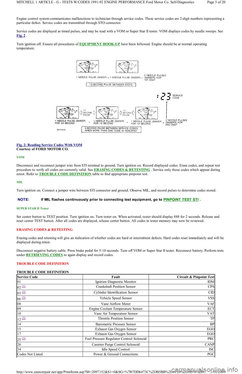
Service codes are displayed as timed pulses, and may be read with a VOM or Super Star II tester. VOM displays codes by needle sweeps. See
Fig. 2
.
Turn ignition off. Ensure all procedures of EQUIPMENT HOOK
-UP have been followed. Engine should be at normal operating
temperature.
Fig. 2: Reading Service Codes With VOM
Courtesy of FORD MOTOR CO.
VOM
Disconnect and reconnect jumper wire from STI terminal to ground. Turn ignition on. Record displayed codes. Erase codes, and repeat test
procedure to verify all codes are currently valid. See ERASING CODES & RETESTING . Service only those codes which appear during
retest. Refer to TROUBLE CODE DEFINITION
table to find appropriate pinpoint test.
MIL
Turn ignition on. Connect a jumper wire between STI connector and ground. Observe MIL, and record pulses to determine codes stored.
SUPER STAR II Tester
Set center button to TEST position. Turn ignition on. Turn tester on. When activated, tester should display 888 for 2 seconds. Release and
reset center TEST button. After all codes are displayed, release center button. All codes in tester memory may now be reviewed.
ERASING CODES & RETESTING
Erasing codes and retesting will give an indication of whether codes are hard or intermittent defects. Hard codes reset immediately and will be
displayed during retest.
Disconnect negative battery cable. Press brake pedal for 5-10 seconds. Turn off VOM or Super Star II tester. Reconnect battery. Perform tests
under RETRIEVING CODES
to again display and record codes.
TROUBLE CODE DEFINITION
TROUBLE CODE DEFINITION
NOTE:If MIL flashes continuously prior to connecting test equipm ent, go to PINPOINT T EST ST I .
Service CodeFaultCircuit & Pinpoint Test
01Ignition Diagnostic MonitorIDM
02 (1) Crankshaft Position SensorCPS
03 (2) Cylinder Identification SensorCID
06 (2) Vehicle Speed SensorVSS
08Vane Airflow MeterVAF
09Engine Coolant Temperature SensorECT
10Vane Air Temperature SensorVAT
12 (2) Throttle Position SensorTP
14Barometric Pressure SensorBP
15Exhaust Gas Oxygen SensorEGO
17Exhaust Gas Oxygen SensorEGO
25 (2) Fuel Pressure Regulator Control SolenoidPRC
26Canister Purge Control SolenoidCANP
34Idle Speed ControlISC
Codes Not ListedPower & Ground ConnectionsPGC
Page 3 of 20 MITCHELL 1 ARTICLE - G - TESTS W/CODES 1991-92 ENGINE PERFORMANCE Ford Motor Co. Self-Diagnostics
3/10/2009 http://www.eautorepair.net/app/PrintItems.asp?S0=2097152&S1=0&SG=%7B7DD6473C%2DB5BB%2D4F20%2D9D70%2D
...
Page 194 of 454

located under the center of the instrument panel, between the panel and the floor.
Fig. 4: Electric Fuel Pump System Schematic
Courtesy of FORD MOTOR CO.
FUEL PRESSURE REGULATOR
The fuel pressure regulator is located at the fuel return end of the fuel rail and maintains fuel pressure within the fuel rail at a constant 36.3 psi
(2.54 kg/cm
2 ) higher than intake manifold pressure.
FUEL PRESSURE REGULATOR CONTROL SOLENOID (PRC) (CAPRI)
This device closes the vacuum supply to the fuel pressure regulator on hot starts, thus increasing fuel pressure within the fuel rail and
preventing fuel percolation which could cause hard starts during hot conditions. The PRC is located on the cowl panel, next to the canister
purge solenoid.
FUEL PUMP SHUT-OFF (INERTIA) SWITCH
The fuel pump shut-off switch is connected in series with the fuel pump and prevents fuel pump operation in the event of major collision or
vehicle rollover. A reset button is provided to reset the switch after it has been triggered. See Fig. 5
.
Fig. 5: Locating Inertia Switch Reset Button
Courtesy of FORD MOTOR CO.
FUEL CONTROL SYSTEM
ELECTRONIC FUEL INJECTION (EFI)
The ECA receives a signal from the CPS (Festiva) or CID (Capri) for basic fuel injector timing. Signals to the ECA from other sensors and
switches affect injector on-time. The amount of fuel injected is determined by the duration of the electronic pulse sent to the fuel injector from
the ECA.
Between idle and 5000 RPM, fuel is supplied by providing one injection per crankshaft rotation (2 injections per cycle) to all cylinders. There
is one injection per 2 crankshaft rotations when engine speed exceeds 5000 RPM. When engine speed exceeds 6400 RPM, fuel injectors are
shut off to prevent engine damage.
Page 4 of 6 MITCHELL 1 ARTICLE - E - THEORY/OPERATION 1991 ENGINE PERFORMANCE Ford/Mercury Theory & Operation
3/10/2009 http://www.eautorepair.net/app/PrintItems.asp?S0=2097152&S1=0&SG=%7B7DD6473C%2DB5BB%2D4F20%2D9D70%2D
...
Page 222 of 454
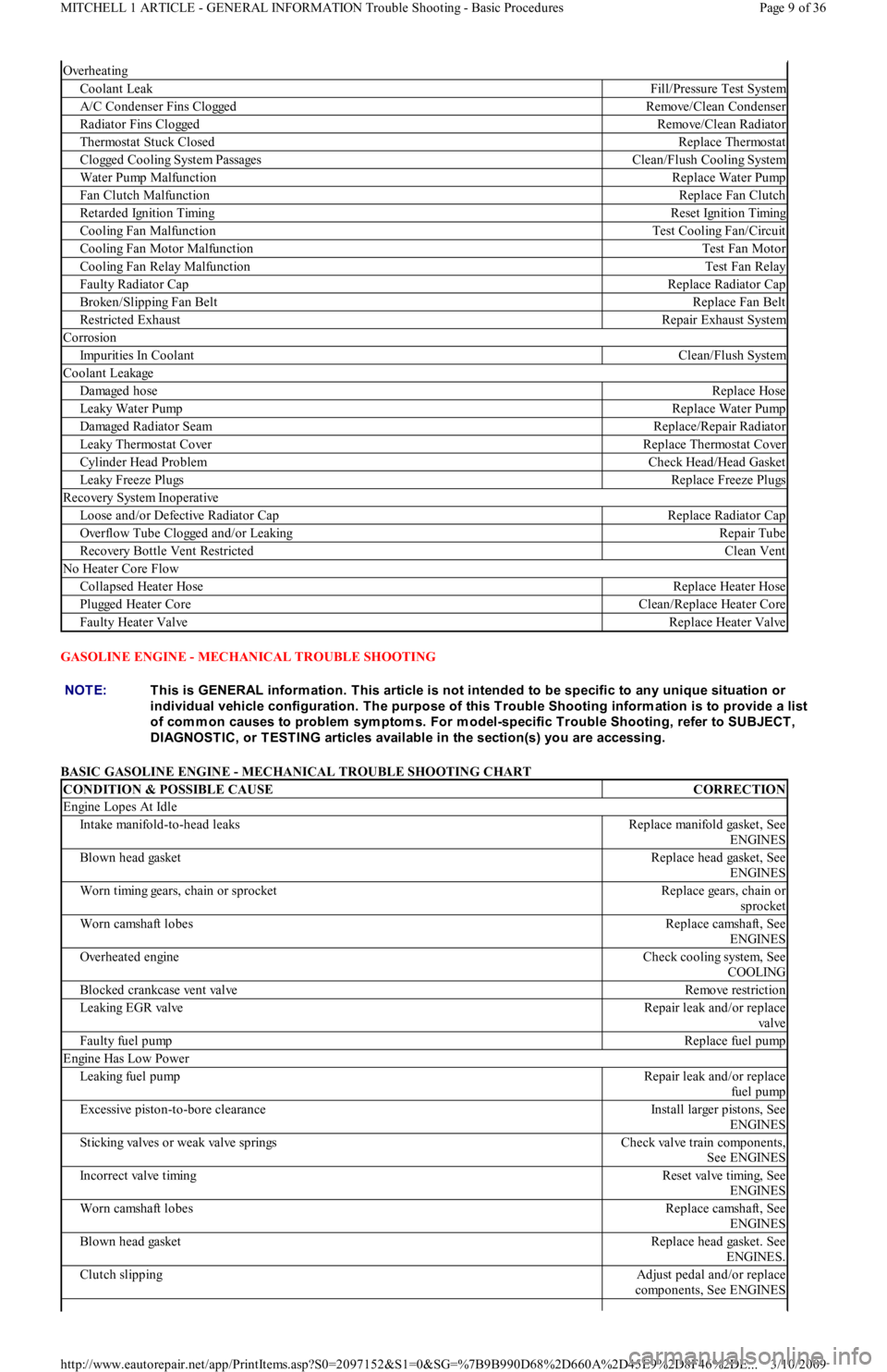
GASOLINE ENGINE - MECHANICAL TROUBLE SHOOTING
BASIC GASOLINE ENGINE - MECHANICAL TROUBLE SHOOTING CHART
Overheating
Coolant LeakFill/Pressure Test System
A/C Condenser Fins CloggedRemove/Clean Condenser
Radiator Fins CloggedRemove/Clean Radiator
Thermostat Stuck ClosedReplace Thermostat
C l o gge d C o o l in g S yst e m P a ssa ge sClean/Flush Cooling System
Water Pump MalfunctionReplace Water Pump
Fan Clutch MalfunctionReplace Fan Clutch
Retarded Ignition TimingReset Ignition Timing
Cooling Fan MalfunctionTest Cooling Fan/Circuit
Cooling Fan Motor MalfunctionTest Fan Motor
Cooling Fan Relay MalfunctionTest Fan Relay
Faulty Radiator CapReplace Radiator Cap
Broken/Slipping Fan BeltReplace Fan Belt
Restricted ExhaustRepair Exhaust System
Corrosion
Impurities In CoolantClean/Flush System
Coolant Leakage
Damaged hoseReplace Hose
Leaky Water PumpReplace Water Pump
Damaged Radiator SeamReplace/Repair Radiator
Leaky Thermostat CoverReplace Thermostat Cover
Cylinder Head ProblemCheck Head/Head Gasket
Leaky Freeze PlugsReplace Freeze Plugs
Recovery System Inoperative
Loose and/or Defective Radiator CapReplace Radiator Cap
Overflow Tube Clogged and/or LeakingRepair Tube
Recovery Bottle Vent RestrictedClean Vent
No Heater Core Flow
Collapsed Heater HoseReplace Heater Hose
Pl u gge d He a t e r C o r eClean/Replace Heater Core
Faulty Heater ValveReplace Heater Valve
NOTE:This is GENERAL inform ation. This article is not intended to be specific to any unique situation or
individual vehicle configuration. T he purpose of this T rouble Shooting inform ation is to provide a list
of com m on causes to problem sym ptom s. For m odel-specific T rouble Shooting, refer to SUBJECT ,
DIAGNOST IC, or T EST ING articles available in the section(s) you are accessing.
CONDITION & POSSIBLE CAUSECORRECTION
Engine Lopes At Idle
In t ake man ifo l d -t o -h ead l eaksReplace manifold gasket, See
ENGINES
Blown head gasketReplace head gasket, See
ENGINES
Worn timing gears, chain or sprocketReplace gears, chain or
sprocket
Worn camshaft lobesReplace camshaft, See
ENGINES
Overheated engineCheck cooling system, See
COOLING
Blocked crankcase vent valveRemove restriction
Le a kin g E GR va l veRepair leak and/or replace
va l ve
Faulty fuel pumpReplace fuel pump
Engine Has Low Power
Leaking fuel pumpRepair leak and/or replace
fu el p u mp
Excessive piston-to-bore clearanceInstall larger pistons, See
ENGINES
Sticking valves or weak valve springsCheck valve train components,
See ENGINES
Incorrect valve timingReset valve timing, See
ENGINES
Worn camshaft lobesReplace camshaft, See
ENGINES
Blown head gasketReplace head gasket. See
ENGINES.
Clutch slippingAdjust pedal and/or replace
components, See ENGINES
Page 9 of 36 MITCHELL 1 ARTICLE - GENERAL INFORMATION Trouble Shooting - Basic Procedures
3/10/2009 http://www.eautorepair.net/app/PrintItems.asp?S0=2097152&S1=0&SG=%7B9B990D68%2D660A%2D45E9%2D8F46%2DE
...
Page 223 of 454
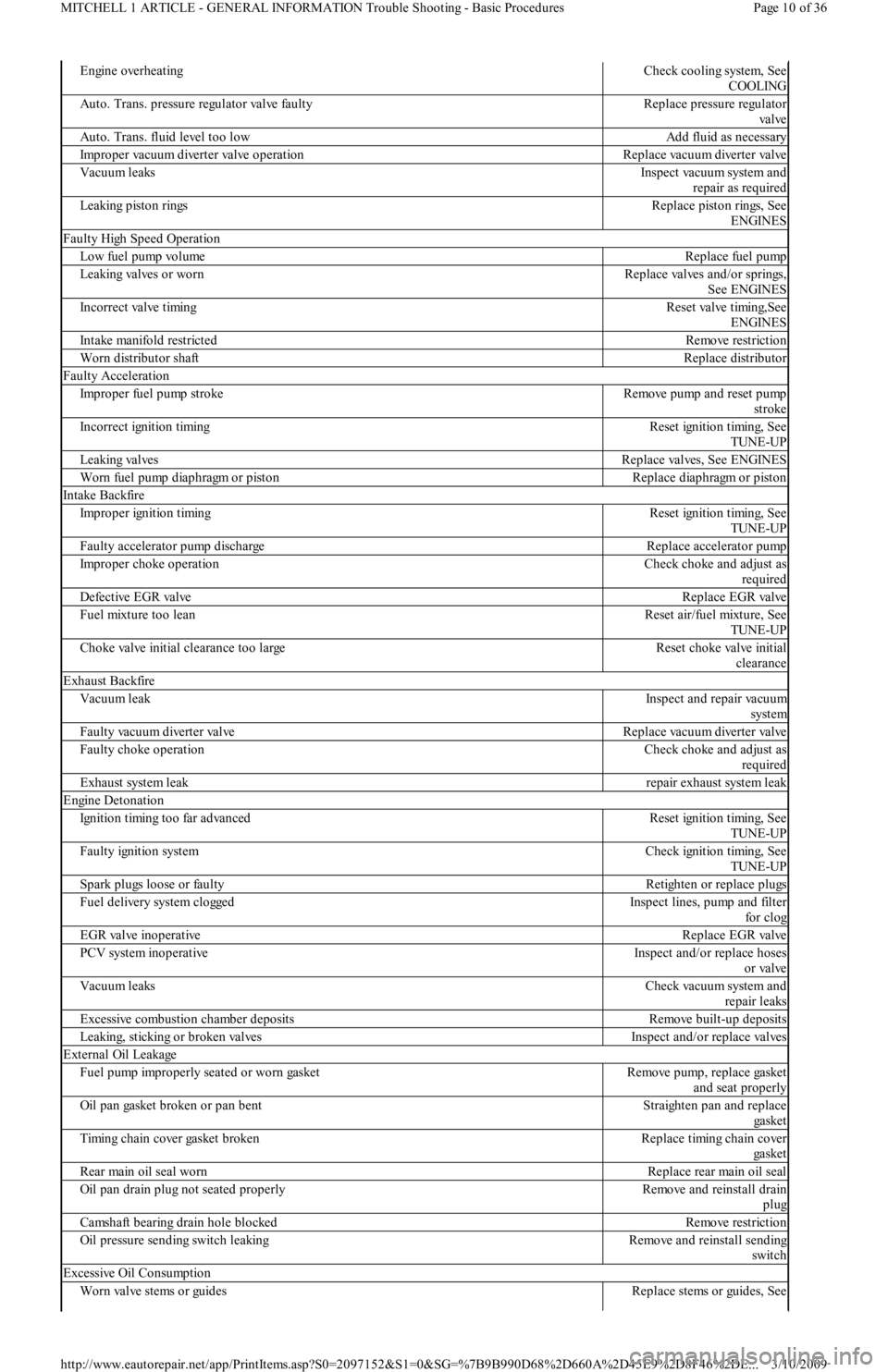
Engine overheatingCheck cooling system, See
COOLING
Auto. Trans. pressure regulator valve faultyReplace pressure regulator
va l ve
Auto. Trans. fluid level too lowAdd fluid as necessary
Improper vacuum diverter valve operationReplace vacuum diverter valve
Vacuum leaksInspect vacuum system and
repair as required
Leaking piston ringsReplace piston rings, See
ENGINES
Faulty High Speed Operation
Low fuel pump volumeReplace fuel pump
Le a kin g va l ve s o r wo r nReplace valves and/or springs,
See ENGINES
Incorrect valve timingReset valve timing,See
ENGINES
In t ake man ifo l d rest rict edRemove restriction
Worn distributor shaftReplace distributor
Faulty Acceleration
Improper fuel pump strokeRemove pump and reset pump
stroke
Incorrect ignition timingReset ignition timing, See
TUNE-UP
Le a kin g va l ve sReplace valves, See ENGINES
Worn fuel pump diaphragm or pistonReplace diaphragm or piston
In t ake Backfire
Improper ignition timingReset ignition timing, See
TUNE-UP
Faulty accelerator pump dischargeReplace accelerator pump
Improper choke operationCheck choke and adjust as
required
Defective EGR valveReplace EGR valve
Fuel mixture too leanReset air/fuel mixture, See
TUNE-UP
Choke valve initial clearance too largeReset choke valve initial
clearance
Exhaust Backfire
Vacuum leakInspect and repair vacuum
system
Faulty vacuum diverter valveReplace vacuum diverter valve
Faulty choke operationCheck choke and adjust as
required
Exhaust system leakrepair exhaust system leak
Engine Detonation
Ignition timing too far advancedReset ignition timing, See
TUNE-UP
Faulty ignition systemCheck ignition timing, See
TUNE-UP
Spark plugs loose or faultyRetighten or replace plugs
Fuel delivery system cloggedInspect lines, pump and filter
fo r cl o g
EGR valve inoperativeReplace EGR valve
PCV system inoperativeInspect and/or replace hoses
or valve
Vacuum leaksCheck vacuum system and
repair leaks
Excessive combustion chamber depositsRemove built-up deposits
Leaking, sticking or broken valvesInspect and/or replace valves
External Oil Leakage
Fuel pump improperly seated or worn gasketRemove pump, replace gasket
and seat properly
Oil pan gasket broken or pan bentStraighten pan and replace
ga ske t
Timing chain cover gasket brokenReplace timing chain cover
ga ske t
Rear main oil seal wornReplace rear main oil seal
Oil pan drain plug not seated properlyRemove and reinstall drain
plug
Camshaft bearing drain hole blockedRemove restriction
Oil pressure sending switch leakingRemove and reinstall sending
switch
Excessive Oil Consumption
Worn valve stems or guidesReplace stems or guides, See
Page 10 of 36 MITCHELL 1 ARTICLE - GENERAL INFORMATION Trouble Shooting - Basic Procedures
3/10/2009 http://www.eautorepair.net/app/PrintItems.asp?S0=2097152&S1=0&SG=%7B9B990D68%2D660A%2D45E9%2D8F46%2DE
...