1991 FORD FESTIVA window
[x] Cancel search: windowPage 7 of 454
Back To Article
DEFOGGER - REAR WINDOW
1991 ACCESSORIES & SAFET Y EQUIPMENT Rear Window Defoggers - Rear Window
DESCRIPTION & OPERATION
The rear window defogger consists of an electrical grid on rear window glass. The rear window defogger switch is located in the instrument
cluster bezel. On Capri, the switch is a push type and includes a small indicator light in the switch to indicate when rear defogger is on. On
Festiva, the switch is a rocker type and includes a small indicator light in instrument cluster to indicate when rear defogger is on.
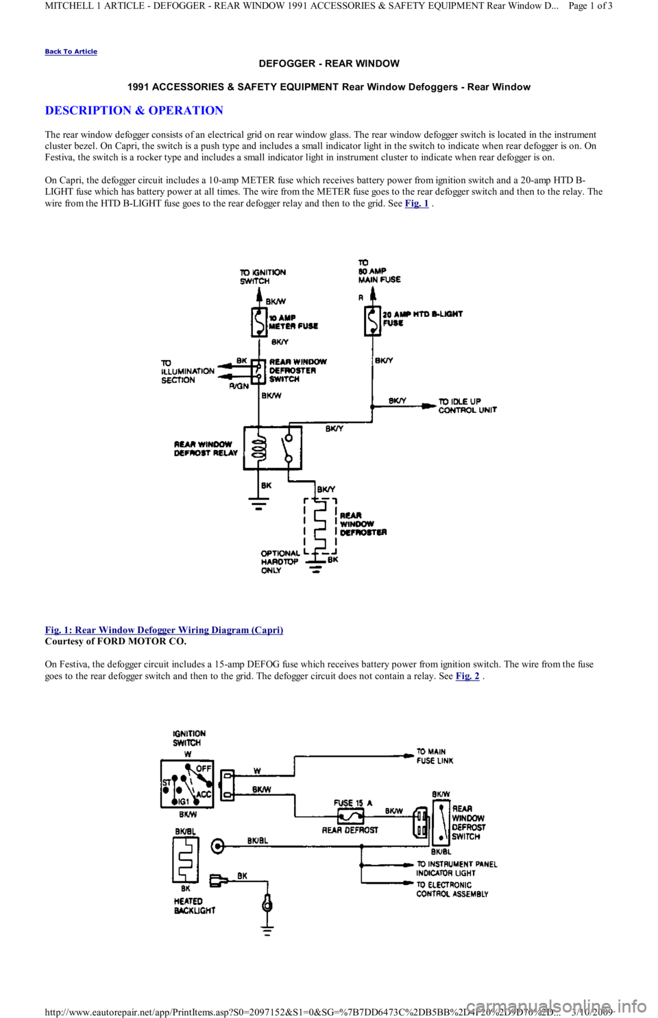
On Capri, the defogger circuit includes a 10-amp METER fuse which receives battery power from ignition switch and a 20-amp HTD B-
LIGHT fuse which has battery power at all times. The wire from the METER fuse goes to the rear defogger switch and then to the relay. The
wire from the HTD B-LIGHT fuse goes to the rear defogger relay and then to the grid. See Fig. 1
.
Fig. 1: Rear Window Defogger Wiring Diagram (Capri)
Courtesy of FORD MOTOR CO.
On Festiva, the defogger circuit includes a 15-amp DEFOG fuse which receives battery power from ignition switch. The wire from the fuse
goes to the rear defogger switch and then to the grid. The defogger circuit does not contain a relay. See Fig. 2
.
Page 1 of 3 MITCHELL 1 ARTICLE - DEFOGGER - REAR WINDOW 1991 ACCESSORIES & SAFETY EQUIPMENT Rear Window D
...
3/10/2009 http://www.eautorepair.net/app/PrintItems.asp?S0=2097152&S1=0&SG=%7B7DD6473C%2DB5BB%2D4F20%2D9D70%2D
...
Page 8 of 454
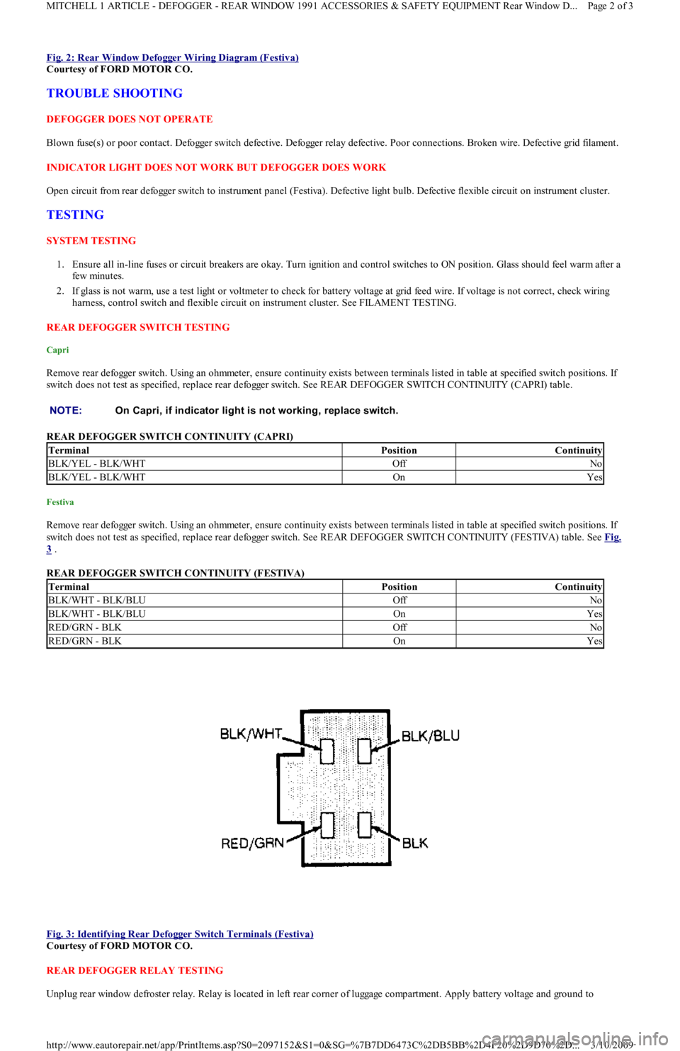
Fig. 2: Rear Window Defogger Wiring Diagram (Festiva)
Courtesy of FORD MOTOR CO.
TROUBLE SHOOTING
DEFOGGER DOES NOT OPERATE
Blown fuse(s) or poor contact. Defogger switch defective. Defogger relay defective. Poor connections. Broken wire. Defective grid filament.
INDICATOR LIGHT DOES NOT WORK BUT DEFOGGER DOES WORK
Open circuit from rear defogger switch to instrument panel (Festiva). Defective light bulb. Defective flexible circuit on instrument cluster.
TESTING
SYSTEM TESTING
1. Ensure all in-line fuses or circuit breakers are okay. Turn ignition and control switches to ON position. Glass should feel warm after a
few min u t es.
2. If glass is not warm, use a test light or voltmeter to check for battery voltage at grid feed wire. If voltage is not correct, check wiring
harness, control switch and flexible circuit on instrument cluster. See FILAMENT TESTING.
REAR DEFOGGER SWITCH TESTING
Capri
Remove rear defogger switch. Using an ohmmeter, ensure continuity exists between terminals listed in table at specified switch positions. If
switch does not test as specified, replace rear defogger switch. See REAR DEFOGGER SWITCH CONTINUITY (CAPRI) table.
REAR DEFOGGER SWITCH CONTINUITY (CAPRI)
Festiva
Remove rear defogger switch. Using an ohmmeter, ensure continuity exists between terminals listed in table at specified switch positions. If
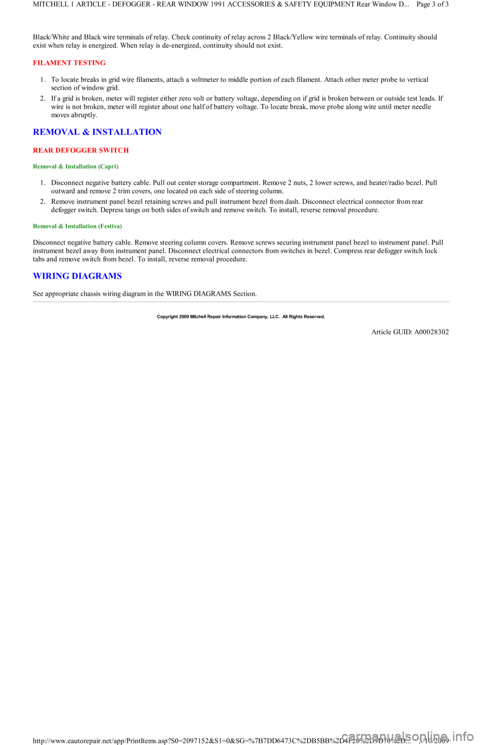
switch does not test as specified, replace rear defogger switch. See REAR DEFOGGER SWITCH CONTINUITY (FESTIVA) table. See Fig.
3 .
REAR DEFOGGER SWITCH CONTINUITY (FESTIVA)
Fig. 3: Identifying Rear Defogger Switch Terminals (Festiva)
Courtesy of FORD MOTOR CO.
REAR DEFOGGER RELAY TESTING
Unplug rear window defroster relay. Relay is located in left rear corner of luggage compartment. Apply battery voltage and ground to NOTE:On Capri, if indicator light is not working, replace switch.
TerminalPositionContinuity
BLK/YEL - BLK/WHTOffNo
BLK/YEL - BLK/WHTOnYes
TerminalPositionContinuity
BLK/WHT - BLK/BLUOffNo
BLK/WHT - BLK/BLUOnYes
RED/GRN - BLKOffNo
RED/GRN - BLKOnYes
Page 2 of 3 MITCHELL 1 ARTICLE - DEFOGGER - REAR WINDOW 1991 ACCESSORIES & SAFETY EQUIPMENT Rear Window D
...
3/10/2009 http://www.eautorepair.net/app/PrintItems.asp?S0=2097152&S1=0&SG=%7B7DD6473C%2DB5BB%2D4F20%2D9D70%2D
...
Page 9 of 454
Black/White and Black wire terminals of relay. Check continuity of relay across 2 Black/Yellow wire terminals of relay. Continuity should
exist when relay is energized. When relay is de-energized, continuity should not exist.
FILAMENT TESTING
1. To locate breaks in grid wire filaments, attach a voltmeter to middle portion of each filament. Attach other meter probe to vertical
section of window grid.
2. If a grid is broken, meter will register either zero volt or battery voltage, depending on if grid is broken between or outside test leads. If
wire is not broken, meter will register about one half of battery voltage. To locate break, move probe along wire until meter needle
mo ves ab ru p t l y.
REMOVAL & INSTALLATION
REAR DEFOGGER SWITCH
Removal & Installation (Capri)
1. Disconnect negative battery cable. Pull out center storage compartment. Remove 2 nuts, 2 lower screws, and heater/radio bezel. Pull
outward and remove 2 trim covers, one located on each side of steering column.
2. Remove instrument panel bezel retaining screws and pull instrument bezel from dash. Disconnect electrical connector from rear
defogger switch. Depress tangs on both sides of switch and remove switch. To install, reverse removal procedure.
Removal & Installation (Festiva)
Disconnect negative battery cable. Remove steering column covers. Remove screws securing instrument panel bezel to instrument panel. Pull
instrument bezel away from instrument panel. Disconnect electrical connectors from switches in bezel. Compress rear defogger switch lock
tabs and remove switch from bezel. To install, reverse removal procedure.
WIRING DIAGRAMS
See appropriate chassis wiring diagram in the WIRING DIAGRAMS Section.
Copyr ight 2009 Mitchell Repair Information Company, LLC. All Rights Reserved.
Article GUID: A00028302
Page 3 of 3 MITCHELL 1 ARTICLE - DEFOGGER - REAR WINDOW 1991 ACCESSORIES & SAFETY EQUIPMENT Rear Window D
...
3/10/2009 http://www.eautorepair.net/app/PrintItems.asp?S0=2097152&S1=0&SG=%7B7DD6473C%2DB5BB%2D4F20%2D9D70%2D
...
Page 10 of 454
Back To Article
1990-92 ACCESSORIES & EQUIPMENT
Power Mirrors - Festiva
DESCRIPTION & OPERATION
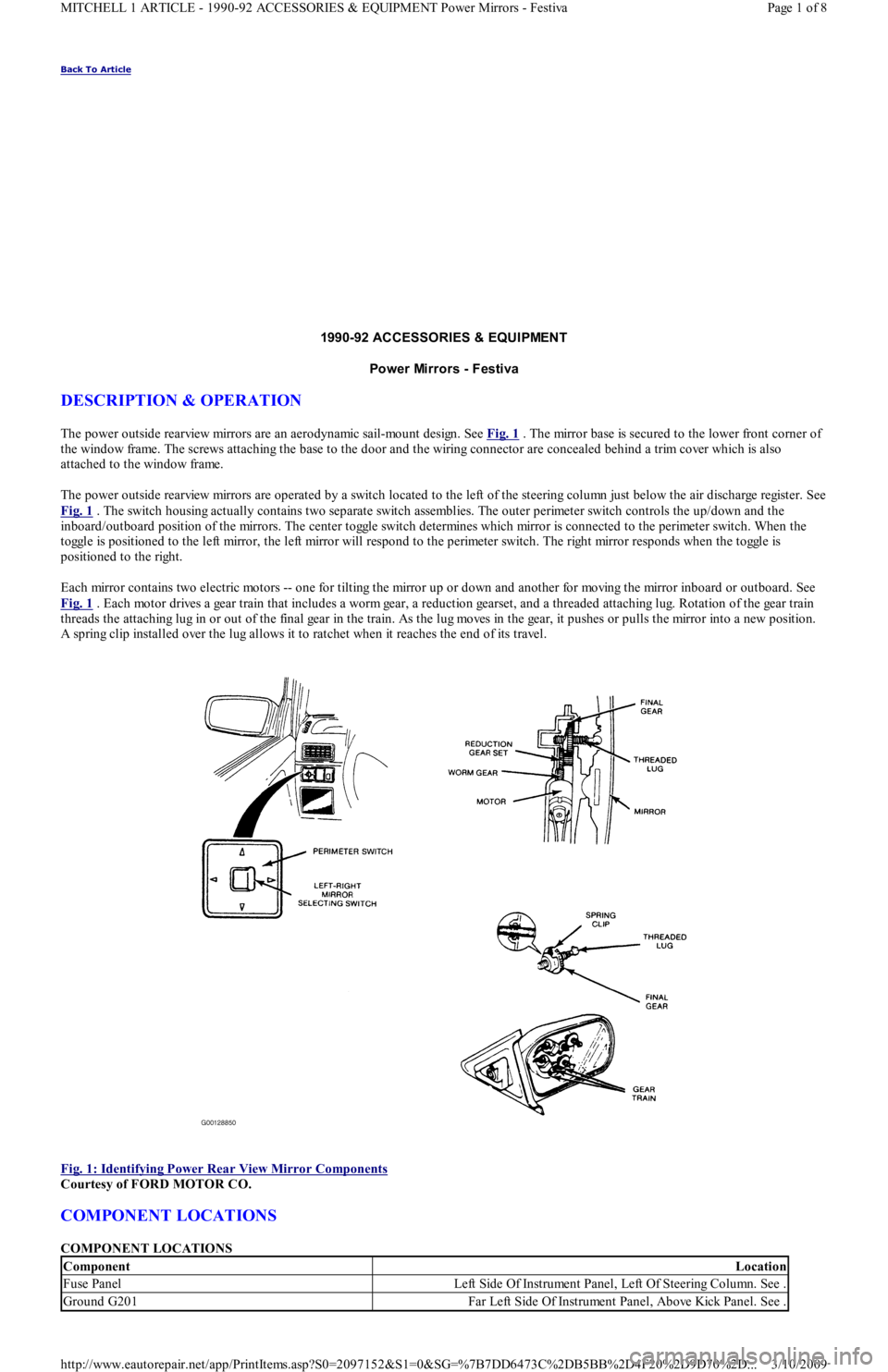
The power outside rearview mirrors are an aerodynamic sail-mount design. See Fig. 1 . The mirror base is secured to the lower front corner of
the window frame. The screws attaching the base to the door and the wiring connector are concealed behind a trim cover which is also
attached to the window frame.
The power outside rearview mirrors are operated by a switch located to the left of the steering column just below the air discharge register. See
Fig. 1
. The switch housing actually contains two separate switch assemblies. The outer perimeter switch controls the up/down and the
inboard/outboard position of the mirrors. The center toggle switch determines which mirror is connected to the perimeter switch. When the
toggle is positioned to the left mirror, the left mirror will respond to the perimeter switch. The right mirror responds when the toggle is
positioned to the right.
Each mirror contains two electric motors -- one for tilting the mirror up or down and another for moving the mirror inboard or outboard. See
Fig. 1
. Each motor drives a gear train that includes a worm gear, a reduction gearset, and a threaded attaching lug. Rotation of the gear train
threads the attaching lug in or out of the final gear in the train. As the lug moves in the gear, it pushes or pulls the mirror into a new position.
A spring clip installed over the lug allows it to ratchet when it reaches the end of its travel.
Fig. 1: Identifying Power Rear View Mirror Components
Courtesy of FORD MOTOR CO.
COMPONENT LOCATIONS
COMPONENT LOCATIONS
ComponentLocation
Fuse PanelLeft Side Of Instrument Panel, Left Of Steering Column. See .
Ground G201Far Left Side Of Instrument Panel, Above Kick Panel. See .
Page 1 of 8 MITCHELL 1 ARTICLE - 1990-92 ACCESSORIES & EQUIPMENT Power Mirrors - Festiva
3/10/2009 http://www.eautorepair.net/app/PrintItems.asp?S0=2097152&S1=0&SG=%7B7DD6473C%2DB5BB%2D4F20%2D9D70%2D
...
Page 23 of 454
Back To Article
WIPER/WASHER SYST EM
1991 ACCESSORIES & SAFET Y EQUIPMENT Ford Motor Co. Wiper/Washer System s
DESCRIPTION & OPERATION
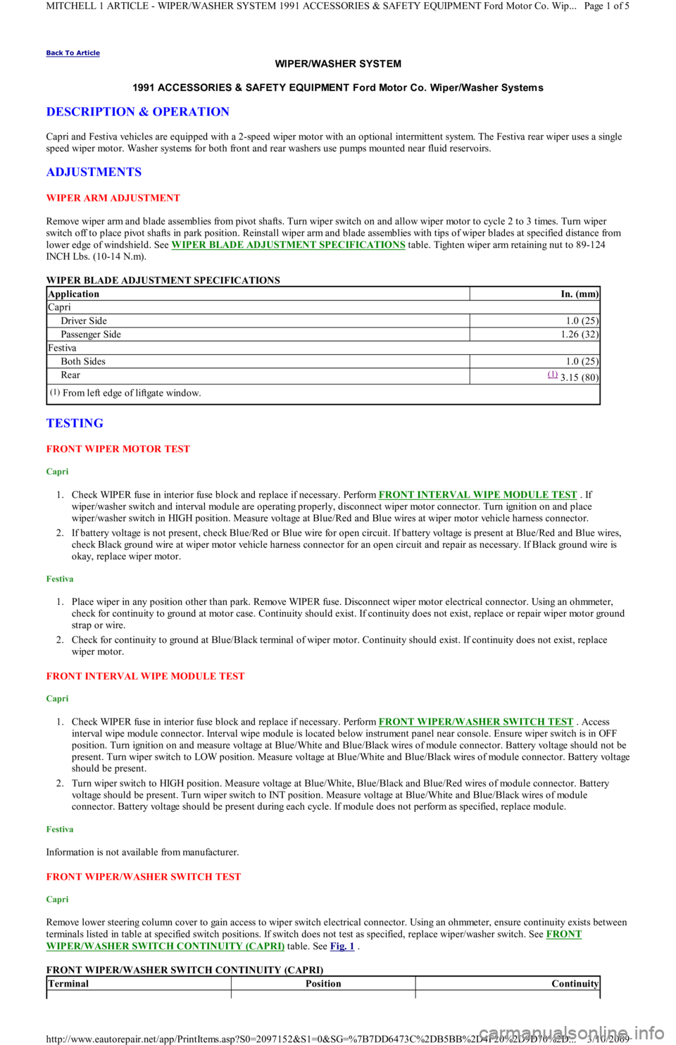
Capri and Festiva vehicles are equipped with a 2-speed wiper motor with an optional intermittent system. The Festiva rear wiper uses a single
speed wiper motor. Washer systems for both front and rear washers use pumps mounted near fluid reservoirs.
ADJUSTMENTS
W IPER ARM ADJUSTMENT
Remove wiper arm and blade assemblies from pivot shafts. Turn wiper switch on and allow wiper motor to cycle 2 to 3 times. Turn wiper
switch off to place pivot shafts in park position. Reinstall wiper arm and blade assemblies with tips of wiper blades at specified distance from
lower edge of windshield. See WIPER BLADE ADJUSTMENT SPECIFICATIONS
table. Tighten wiper arm retaining nut to 89-124
INCH Lbs. (10-14 N.m).
WIPER BLADE ADJUSTMENT SPECIFICATIONS
TESTING
FRONT WIPER MOTOR TEST
Capri
1. Check WIPER fuse in interior fuse block and replace if necessary. Perform FRONT INTERVAL WIPE MODULE TEST . If
wiper/washer switch and interval module are operating properly, disconnect wiper motor connector. Turn ignition on and place
wiper/washer switch in HIGH position. Measure voltage at Blue/Red and Blue wires at wiper motor vehicle harness connector.
2. If battery voltage is not present, check Blue/Red or Blue wire for open circuit. If battery voltage is present at Blue/Red and Blue wires,
check Black ground wire at wiper motor vehicle harness connector for an open circuit and repair as necessary. If Black ground wire is
okay, replace wiper motor.
Festiva
1. Place wiper in any position other than park. Remove WIPER fuse. Disconnect wiper motor electrical connector. Using an ohmmeter,
check for continuity to ground at motor case. Continuity should exist. If continuity does not exist, replace or repair wiper motor ground
strap or wire.
2. Check for continuity to ground at Blue/Black terminal of wiper motor. Continuity should exist. If continuity does not exist, replace
wiper motor.
FRONT INTERVAL WIPE MODULE TEST
Capri
1. Check WIPER fuse in interior fuse block and replace if necessary. Perform FRONT WIPER/WASHER SWITCH TEST . Access
interval wipe module connector. Interval wipe module is located below instrument panel near console. Ensure wiper switch is in OFF
position. Turn ignition on and measure voltage at Blue/White and Blue/Black wires of module connector. Battery voltage should not be
present. Turn wiper switch to LOW position. Measure voltage at Blue/White and Blue/Black wires of module connector. Battery voltage
should be present.
2. Turn wiper switch to HIGH position. Measure voltage at Blue/White, Blue/Black and Blue/Red wires of module connector. Battery
voltage should be present. Turn wiper switch to INT position. Measure voltage at Blue/White and Blue/Black wires of module
connector. Battery voltage should be present during each cycle. If module does not perform as specified, replace module.
Festiva
Information is not available from manufacturer.
FRONT WIPER/WASHER SWITCH TEST
Capri
Remove lower steering column cover to gain access to wiper switch electrical connector. Using an ohmmeter, ensure continuity exists between
terminals listed in table at specified switch positions. If switch does not test as specified, replace wiper/washer switch. See FRONT
WIPER/WASHER SWITCH CONTINUITY (CAPRI) table. See Fig. 1 .
FRONT WIPER/WASHER SWITCH CONTINUITY (CAPRI)
ApplicationIn. (mm)
Capri
Driver Side1.0 (25)
Passenger Side1.26 (32)
Festiva
Both Sides1.0 (25)
Rear(1) 3.15 (80)
(1)From left edge of liftgate window.
TerminalPositionContinuity
Page 1 of 5 MITCHELL 1 ARTICLE - WIPER/WASHER SYSTEM 1991 ACCESSORIES & SAFETY EQUIPMENT Ford Motor Co. Wip
...
3/10/2009 http://www.eautorepair.net/app/PrintItems.asp?S0=2097152&S1=0&SG=%7B7DD6473C%2DB5BB%2D4F20%2D9D70%2D
...
Page 49 of 454
Back To Article
FUSES & CIRCUIT BREAKERS
Fuses & Circuit Breakers 1988-93 Festiva
FUSES & FUSIBLE LINKS
FUSE PANEL & FUSIBLE LINK BLOCK LOCATIONS
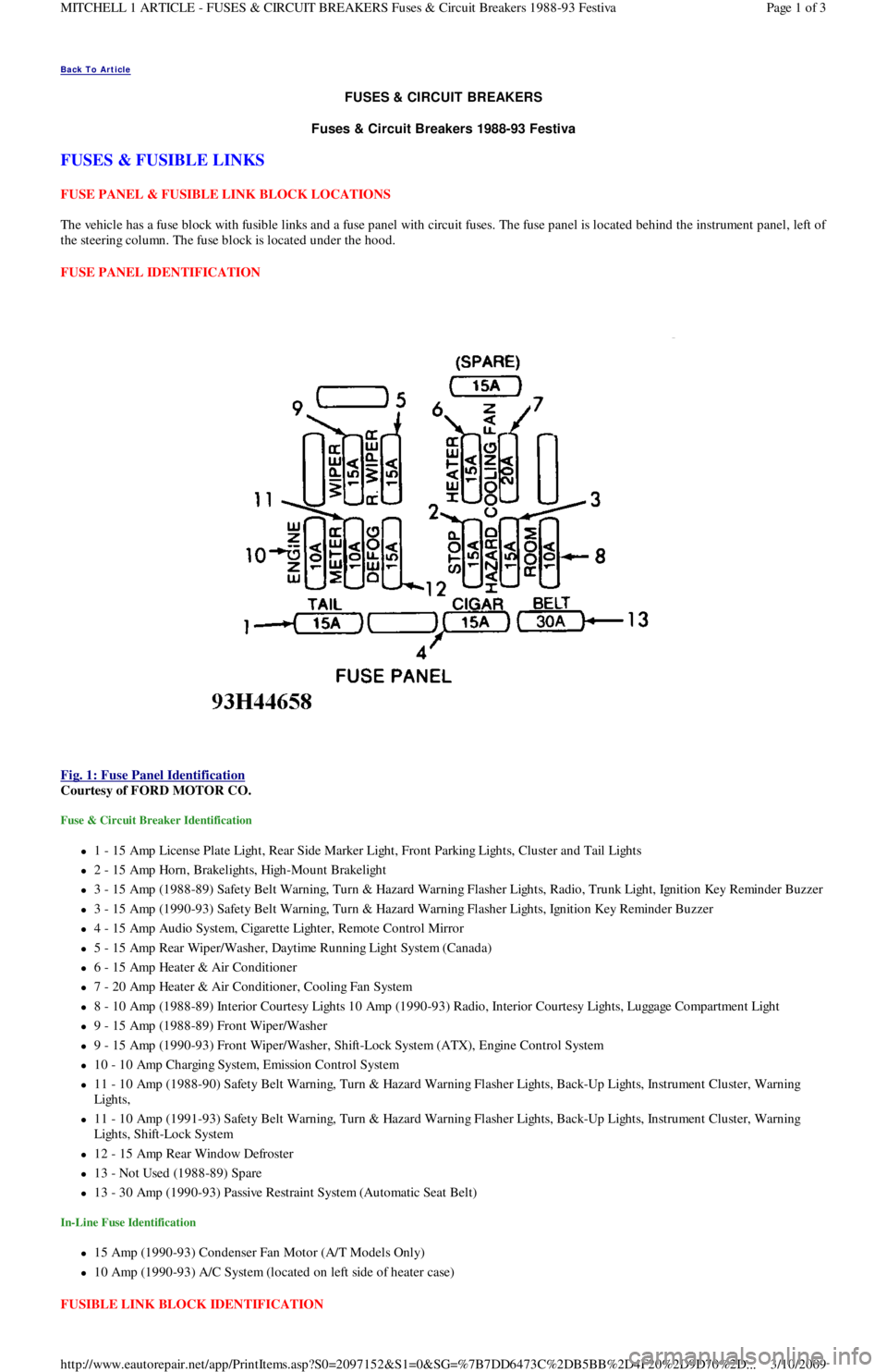
The vehicle has a fuse block with fusible links and a fuse panel with circuit fuses. The fuse panel is located behind the instrument panel, left o
f
the steering column. The fuse block is located under the hood.
FUSE PANEL IDENTIFICATION
Fig. 1: Fuse Panel Identification
Courtesy of FORD MOTOR CO.
Fuse & Circuit Breaker Identification
1 - 15 Amp License Plate Light, Rear Side Marker Ligh t , Fr o n t P a r kin g Ligh t s, C l u st e r a n d Ta il Ligh t s
2 - 15 Amp Horn, Brakelights, High-Mount Brakelight
3 - 15 Amp (1988-89) Safety Belt Warning, Turn & Hazard Warning Flasher Lights, Radio, Trunk Light, Ignition Key Reminder Buzzer
3 - 15 Amp (1990-93) Safety Belt Warning, Turn & Hazard Warning Flasher Lights, Ignition Key Reminder Buzzer
4 - 15 Amp Audio System, Cigarette Lighter, Remote Control Mirror
5 - 15 Amp Rear Wiper/Washer, Daytime Running Light System (Canada)
6 - 15 Amp Heater & Air Conditioner
7 - 20 Amp Heater & Air Conditioner, Cooling Fan System
8 - 10 Amp (1988-89) Interior Courtesy Lights 10 Amp (1990-93) Radio, Interior Courtesy Lights, Luggage Compartment Light
9 - 15 Amp (1988-89) Front Wiper/Washer
9 - 15 Amp (1990-93) Front Wiper/Washer, Shift-Lock System (ATX), Engine Control System
10 - 10 Amp Charging System, Emission Control System
11 - 10 Amp (1988-90) Safety Belt Warning, Turn & Hazard Warning Flasher Lights, Back-Up Lights, Instrument Cluster, Warning
Lights,
11 - 10 Amp (1991-93) Safety Belt Warning, Turn & Hazard Warning Flasher Lights, Back-Up Lights, Instrument Cluster, Warning
Lights, Shift-Lock System
12 - 15 Amp Rear Window Defroster
13 - Not Used (1988-89) Spare
13 - 30 Amp (1990-93) Passive Restraint System (Automatic Seat Belt)
In-Line Fuse Identification
15 Amp (1990-93) Condenser Fan Motor (A/T Models Only)
10 Amp (1990-93) A/C System (located on left side of heater case)
FUSIBLE LINK BLOCK IDENTIFICATION
Page 1 of 3 MITCHELL 1 ARTICLE - FUSES & CIRCUIT BREAKERS Fuses & Circuit Breakers 1988-93 Festiva
3/10/2009 http://www.eautorepair.net/app/PrintItems.asp?S0=2097152&S1=0&SG=%7B7DD6473C%2DB5BB%2D4F20%2D9D70%2D
...
Page 50 of 454
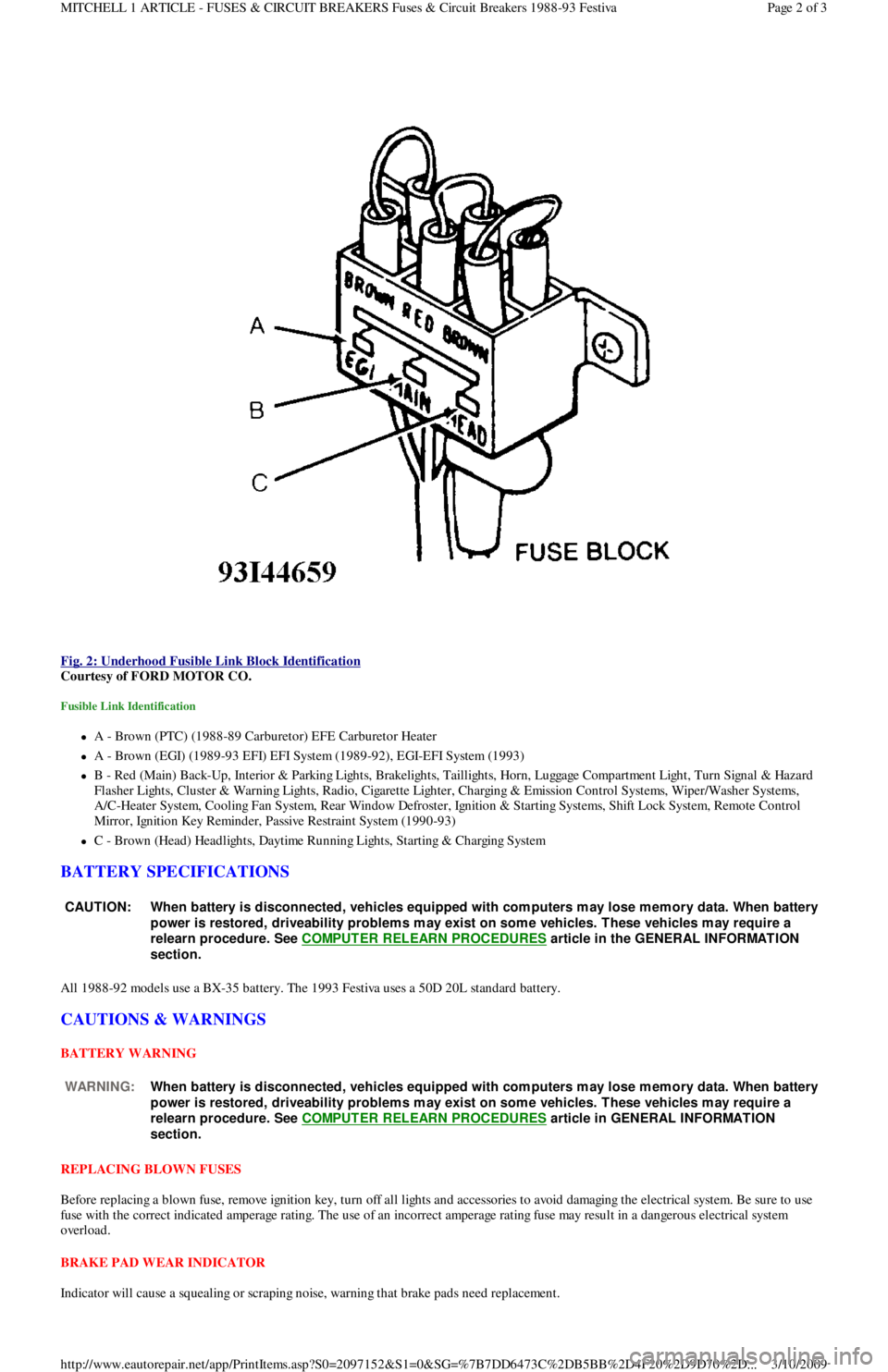
Fig. 2: Underhood Fusible Link Block Identification
Courtesy of FORD MOTOR CO.
Fusible Link Identification
A - Brown (PTC) (1988-89 Carburetor) EFE Carburetor Heater
A - Brown (EGI) (1989-93 EFI) EFI System (1989-92), EGI-EFI System (1993)
B - Red (Main) Back-Up, Interior & Parking Lights, Brakelights, Taillights, Horn, Luggage Compartment Light, Turn Signal & Hazard
F l a sh e r Ligh t s, C l u st e r & Wa r n in g Ligh t s, R a d io , C iga r e t t e Ligh t e r , C h a r gin g & E missio n C o n t r o l S yst e ms, Wip e r / Wa sh e r S yst e ms,
A/C-Heater System, Cooling Fan System, Rear Window Defroster, Ignition & Starting Systems, Shift Lock System, Remote Control
Mirror, Ignition Key Reminder, Passive Restraint System (1990-93)
C - Brown (Head) Headlights, Daytime Running Lights, Starting & Charging System
BATTERY SPECIFICATIONS
All 1988-92 models use a BX-35 battery. The 1993 Festiva uses a 50D 20L standard battery.
CAUTIONS & WARNINGS
BATTERY WARNING
REPLACING BLOWN FUSES
Before replacing a blown fuse, remove ignition key, turn off all lights and accessories to avoid damaging the electrical system. Be sure to use
fuse with the correct indicated amperage rating. The use of an incorrect amperage rating fuse may result in a dangerous electrical system
overload.
BRAKE PAD WEAR INDICATOR
Indicator will cause a squealing or scraping noise, warning that brake pads need replacement.
CAUT ION: When battery is disconnected, vehicles equipped with com puters m ay lose m em ory data. When battery
power is restored, driveability problem s m ay exist on som e vehicles. T hese vehicles m ay require a
relearn procedure. See COMPUTER RELEARN PROCEDURES
article in the GENERAL INFORMAT ION
section.
WARNING:When battery is disconnected, vehicles equipped with com puters m ay lose m em ory data. When battery
power is restored, driveability problem s m ay exist on som e vehicles. T hese vehicles m ay require a
relearn procedure. See COMPUTER RELEARN PROCEDURES
article in GENERAL INFORMAT ION
section.
Page 2 of 3 MITCHELL 1 ARTICLE - FUSES & CIRCUIT BREAKERS Fuses & Circuit Breakers 1988-93 Festiva
3/10/2009 http://www.eautorepair.net/app/PrintItems.asp?S0=2097152&S1=0&SG=%7B7DD6473C%2DB5BB%2D4F20%2D9D70%2D
...
Page 65 of 454

Fig. 2: Ground Numbers & Locations (2001 & Prior Model Years)
WIRING DIAGRAM COMPONENT LOCATIONS
When trying to locate a component in a wiring diagram and you don't know the specific system where it is located, use this handy component
locator to find the system wiring diagram in which the component is located. Then, go to that system and locate the component within the
wiring diagram.
For example, if you don't know the specific system in which the ignition switch is located, look up ignition switch in the wiring diagram
component location tables and go to the appropriate wiring diagram(s) which contain either full or partial views of the ignition switch. The full
view of the ignition switch is located in Power Distribution.
The first listing for the component will be the full or most complete view of the component. Additional listings will be partial views of the
component. Not all components are used on all models.
All components will have a partial view in Ground Distribution and Power Distribution. Data Link Connectors show connecting circuits
between modules. Alternate names for components may be listed in wiring diagram component locations tables.
WIRING DIAGRAM COMPONENT LOCATIONS
ComponentWiring Diagram
ABS Electronic Control UnitAnti-Lock Brakes; Data Link Connectors
ABS Hydraulic UnitAnti-Lock Brakes
Acceleration SensorAnti-Lock Brakes
Accessory Delay RelayPower Windows
A/C Compressor Clutch RelayEngine Performance
A/C SensorEngine Performance
A/C Pressure SwitchEngine Performance
Adaptive Lamp Control ModuleExterior Lights
Air Bag(s)Air Bag Restraint System
Air Bag ModuleAir Bag Restraint System
Air Bag Sensor(s)Air Bag Restraint System
Air Injection Pump RelayEngine Performance
Air Temperature SensorOverhead Console
Alternator (Generator)Generators & Regulators
Anti-Theft Control ModuleAnti-Theft System; Starters
Page 3 of 6 MITCHELL 1 ARTICLE - GENERAL INFORMATION Using Mitchell1's Wiring Diagrams
3/10/2009 http://www.eautorepair.net/app/PrintItems.asp?S0=2097152&S1=0&SG=%7B959286D2%2D3A85%2D4BFC%2D9C5C%2D
...