1990 MITSUBISHI SPYDER fuel pump
[x] Cancel search: fuel pumpPage 608 of 2103
ENGINE (TURBO)
AND ENGINE> Troubleshooting
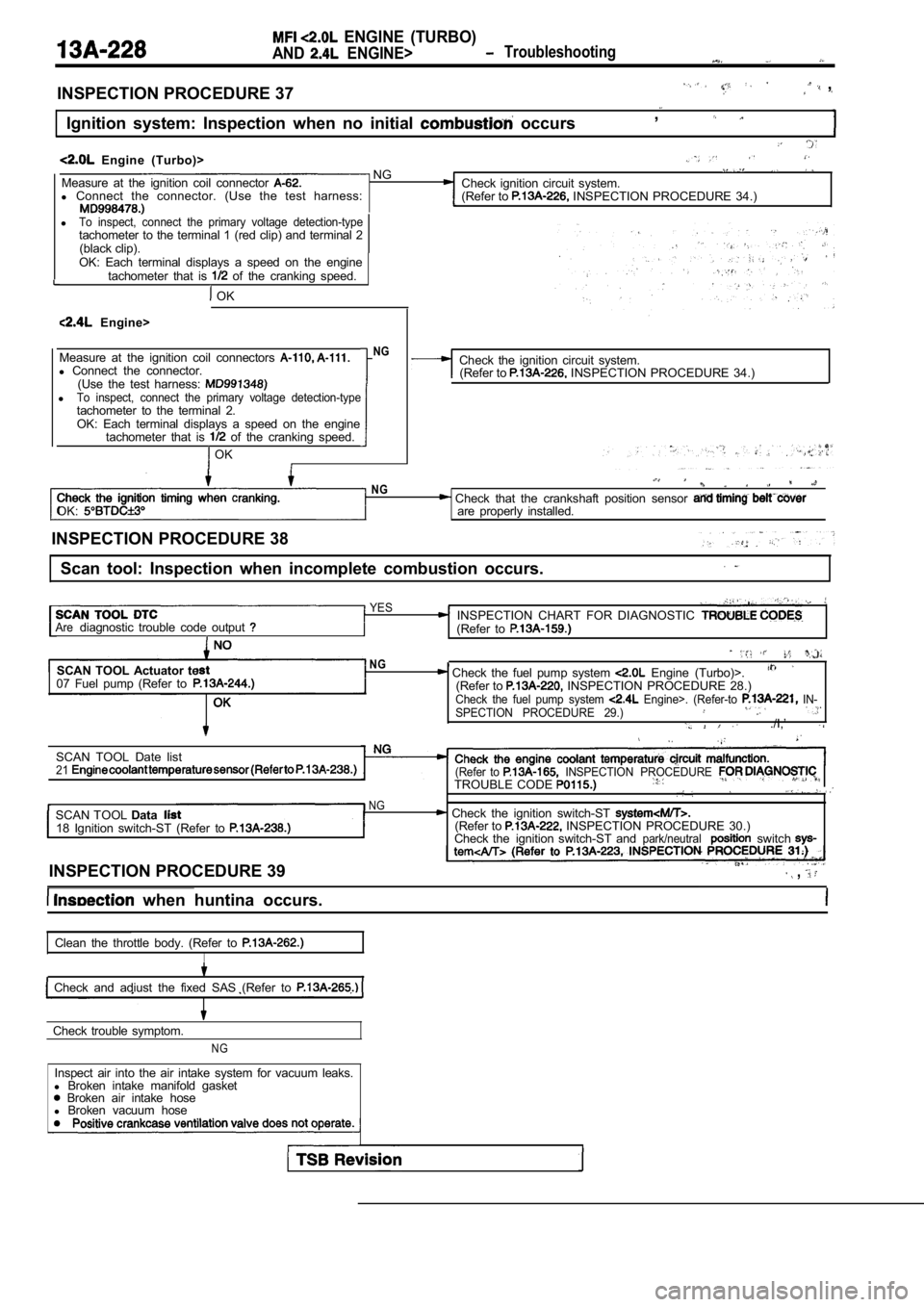
INSPECTION PROCEDURE 37 ,
Ignition system: Inspection when no initial occurs,
Engine (Turbo)> NGMeasure at the ignition coil connector Check ignition circuit system.
l Connect the connector. (Use the test harness:
(Refer to INSPECTION PROCEDURE 34.)
lTo inspect, connect the primary voltage detection-typetachometer to the terminal 1 (red clip) and terminal 2
(black clip).
OK: Each terminal displays a speed on the engine tachometer that is
of the cranking speed.
OK
Engine>
Measure at the ignition coil connectors
l Connect the connector.
(Use the test harness:
lTo inspect, connect the primary voltage detection-t ypetachometer to the terminal 2.OK: Each terminal displays a speed on the engine
tachometer that is of the cranking speed.
OK
NGCheck the ignition circuit system.(Refer to INSPECTION PROCEDURE 34.)
OK:
NG Check that the crankshaft position sensor are properly installed.
INSPECTION PROCEDURE 38
Scan tool: Inspection when incomplete combustion oc curs.
YESINSPECTION CHART FOR DIAGNOSTIC Arediagnostic trouble code output (Refer to
SCAN TOOL Actuator te
07 Fuel pump (Refer toNG, Check the fuel pump system Engine (Turbo)>.(Refer to INSPECTION PROCEDURE 28.)Check the fuel pump system Engine>. (Refer-to IN-
SPECTION PROCEDURE 29.)
./I,’
SCAN TOOL Date list21(Refer to INSPECTION PROCEDURE TROUBLE CODE
NGSCAN TOOL Data Check the ignition switch-ST 18 Ignition switch-ST (Refer to (Refer to INSPECTION PROCEDURE 30.)
Check the ignition switch-ST andpark/neutralswitch
INSPECTION PROCEDURE 39 ,
when huntina occurs.
Clean the throttle body. (Refer to
I
Check and adiust the fixed SAS (Refer to
Check trouble symptom.
NG
Inspect air into the air intake system for vacuum l eaks.
l Broken intake manifold gasket
Broken air intake hose
l Broken vacuum hose
Page 624 of 2103
ENGINE (TURBO)
AND
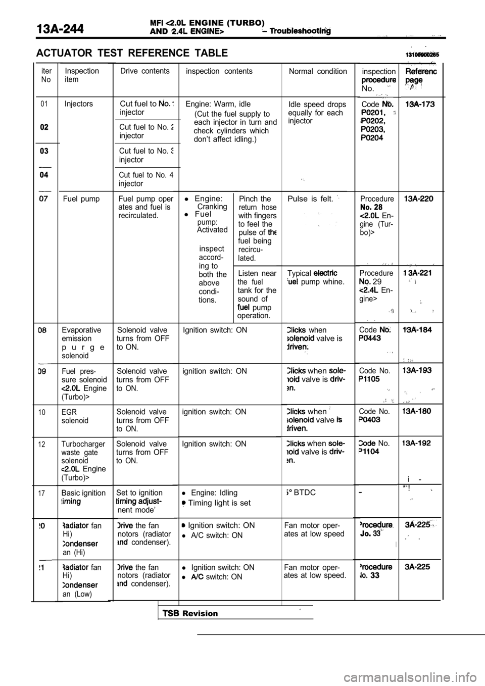
ACTUATOR TEST REFERENCE TABLE
iter
NoDrive contents inspection contents Normal condition
Inspection
iteminspection
No.
Code01
02
Cut fuel to
injector Idle speed drops
equally for each
injector
Engine: Warm, idle
(Cut the fuel supply to
each injector in turn and
check cylinders which don’t affect idling.)
l Engine:Crankingl Fuelpump:Activated
inspect
accord-
ing to
both the
above
condi-
tions. Pinch the
return hose
with fingers
to feel the pulse of
fuel being
recircu-
lated.
Listen near
the fuel
tank for the
sound of
pump
operation.
Injectors
Fuel pump Cut fuel to No.
injector
03
04
Cut fuel to No.
injector
Cut fuel to No. 4
injector
Fuel pump oper
ates and fuel is
recirculated.
Pulse is felt. Procedure
No. 28
En-
gine (Tur-
bo)>
Typical
pump whine.
when
valve is
Procedure
29
En-
gine>
Code
when
valve is
when
valve
Code No.
Code No.
when
valve is
No.
BTDC
Fan motor oper-
ates at low speed
Jo.
l Ignition switch: ON Fan motor oper-
l switch: ON ates at low speed. 33
Evaporative
emission
p u r g e
solenoid
Solenoid valve
turns from OFF
to ON.
. .
i -
*‘!
. .
Ignition switch: ON
Fuel pres-
sure solenoid
Engine
(Turbo)>
ignition switch: ON
Solenoid valve
turns from OFF
to ON.
10EGR
solenoid
ignition switch: ON
Solenoid valve
turns from OFF
to ON.
Solenoid valve
turns from OFF
to ON.
12Ignition switch: ONTurbocharger
waste gate
solenoid
Engine
(Turbo)>
Basic ignitionl Engine: Idling
Timing light is set
17Set to ignition
nent mode’
the fan
notors (radiator
condenser).
Ignition switch: ON
l A/C switch: ON
fan
Hi)
an (Hi)
the fan
notors (radiator
condenser).
fanHi)
an (Low)
Revision
Page 626 of 2103
E N G I N E
AND ENGINE>
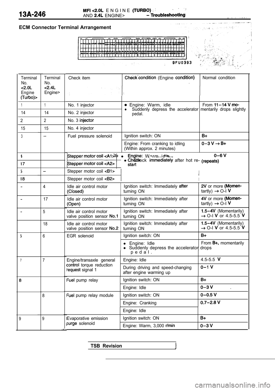
ECM Connector Terminal Arrangement
Check item (Engine Normal conditionTerminalNo.
Engine
TerminalNo.
Engine>
1No. 1 injector Engine: Warm, idleFromlNo. 2 injector Suddenly depress the accelerator mentarily drops sl
ightlypedal.
No. 3
No. 4 injector
Fuel pressure solenoidIgnition switch: ON
Engine: From cranking to idling
(Within approx. 2 minutes)
1
14 14
2
15
2
15
3
l W a r m i d l e
l . Check after hot re-
Stepper motor coil I
Stepper motor coil I
Idle air control motor Ignition switch: Immediately or more
turning ONtartly) O-l
Idle air control motorIgnition switch: Immediately after or more
turning ONtartly) O-l
Idle air control motorIgnition switch: Immediately after (Momentarily)
valve position sensor
turning ON O-l or 4.5-5.5
Idle air control motor Ignition switch: Immediately after (Momentarily)
valve position sensor
turning ON O-l or 4.5-5.5
EGR solenoid Ignition switch: ON
l
Engine: IdleFrom momentarily
l Suddenly depress the accelerator drops
4
17
5
18
6
p e d a l .
Engine/transaxle general Engine: Idle4.5-5.5
torque reduction
signal 1During driving and speed-changingafter engine warming upI
I
I
I
I
pump relay
pump relay module Ignition switch: ON
Engine: Idle
Ignition switch: ON
Engine: Cranking
.
Evaporative emission
solenoid Engine: Idle
Ignition switch: ON
Engine: Warm, 3,000
77
8
9
9
TSB Revision
Page 648 of 2103
Fuel pressure
O-ring or gasket
.
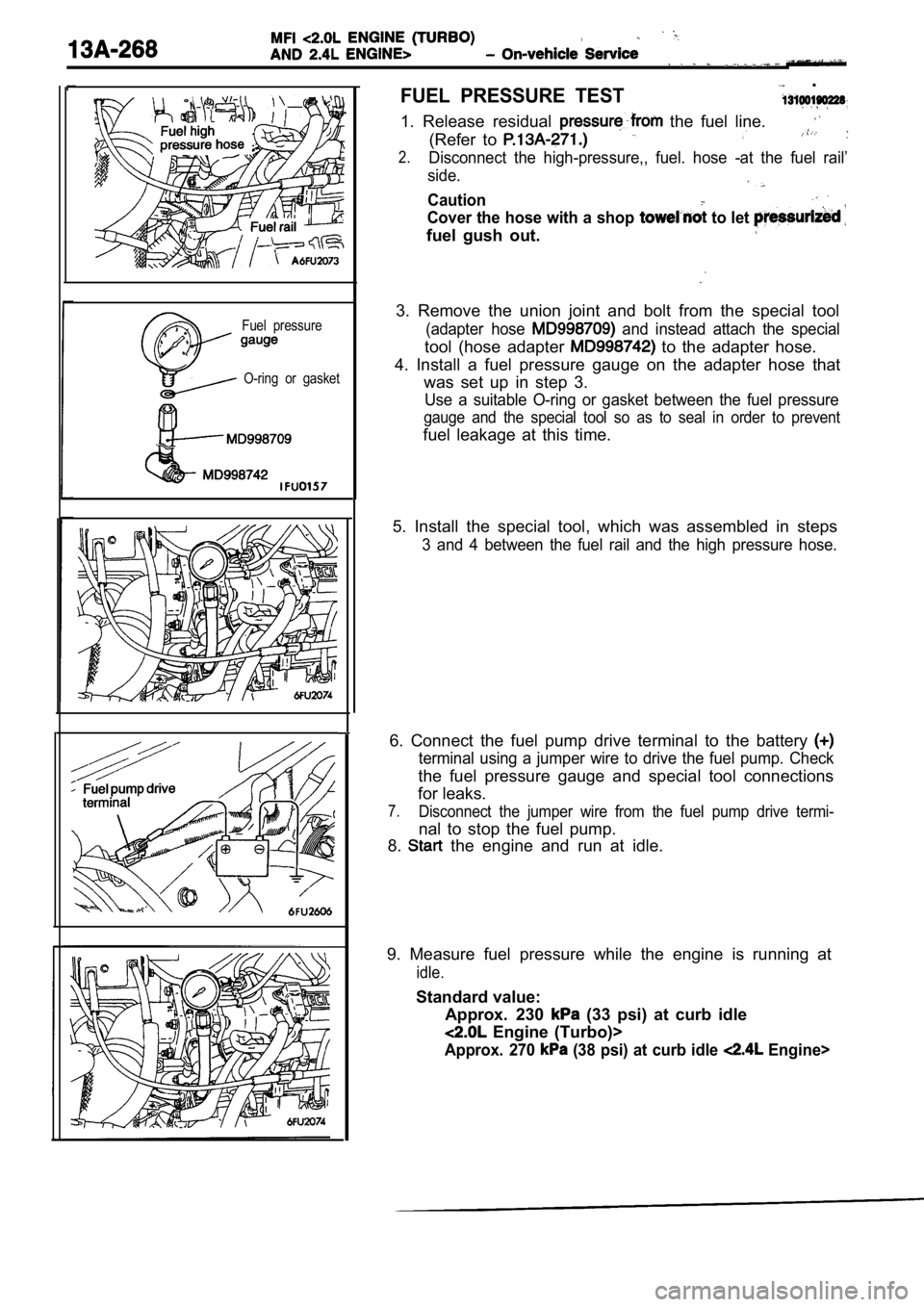
FUEL PRESSURE TEST
1. Release residual the fuel line.
(Refer to
2.Disconnect the high-pressure,, fuel. hose -at the fuel rail’
side.
Caution
Cover the hose with a shop to let
fuel gush out.
3. Remove the union joint and bolt from the special tool
(adapter hose and instead attach the special
tool (hose adapter to the adapter hose.
4. Install a fuel pressure gauge on the adapter hos e that
was set up in step 3.
Use a suitable O-ring or gasket between the fuel pr essure
gauge and the special tool so as to seal in order t o prevent
fuel leakage at this time.
5. Install the special tool, which was assembled in steps
3 and 4 between the fuel rail and the high pressure hose.
6. Connect the fuel pump drive terminal to the batt ery
terminal using a jumper wire to drive the fuel pump. Check
the fuel pressure gauge and special tool connection s
for leaks.
7.Disconnect the jumper wire from the fuel pump drive termi-
nal to stop the fuel pump.
8.
the engine and run at idle.
9. Measure fuel pressure while the engine is runnin g at
idle.
Standard value:
Approx. 230
(33 psi) at curb idle
Engine (Turbo)>
Approx. 270 (38 psi) at curb idle Engine>
Page 649 of 2103
AND On-vehicle
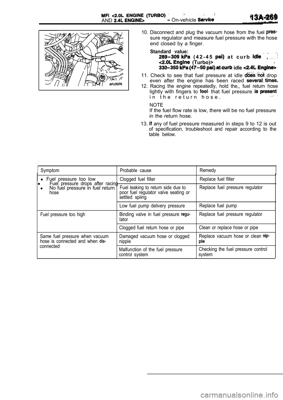
10. Disconnect and plug the vacuum hose from the fuel
sure regulator and measure fuel pressure with the hose
end closed by a finger.
Standard value:
( 4 2 - 4 5 a t c u r b ,
(Turbo)> .
idle
11. Check to see that fuel pressure at idle drop
even after the engine has been raced
12. Racing the engine repeatedly, hold the,, fuel r eturn hose
lightly with fingers to that fuel pressure
i n t h e r e t u r n h o s e .
NOTE
If the fuel flow rate is low, there will be no fuel pressure
in the return hose.
13.
any of fuel pressure measured in steps 9 to 12 is out
of specification, troubleshoot and repair according to the
table below.
Symptom Probable cause Remedy
l Fuel pressure too lowClogged fuel filterReplace fuel filterlFuel pressure drops after racinglNo fuel pressure in fuel returnFuel leaking to return side due toReplace fuel pressure regulator
hose poor fuel regulator valve seating or
settled spiing
Low fuel pump delivery pressure Replace fuel pump
Fuel pressure too high Binding valve in fuel pressure
Replace fuel pressure regulator
lator
Same fuel pressure when vacuum
hose is connected and when
connected Clogged fuel return hose or pipe
Clean or replace hose or pipe
Damaged vacuum hose or clogged Replace vacuum hose or clean
nipple
Malfunction of the fuel pressureChecking the fuel pressure control
control system system
Page 650 of 2103
14. Stop the engine and
Normal if the reading does
it observe
repair according to “the table,
SymptomProbable
Fuel pressure drops gradually afterLeaky injector
engine is stopped inject&. . ,
Leaky fuel regulator valve seat
Fuel pressure drops Check is held. .mediately after engine is stopped open
15. Release residual pressure from the fuel pipe li ne.
(Refer
16. Remove the fuel pressure gauge and special tool from
the fuel rail.
Caution
Cover the hose connection with a shop towel to pre-
vent splash of fuel that could be caused by some residual pressure in the fuel pipe line.
17. Replace the O-ring at the end of the fuel high pressure
hose with a new one.
16. Fit the fuel high pressure the fuel rail and tighten
the bolts specified torque.
T i g h t e n i n g
‘Apply
drive drive the fuel pump.
(2) Check
fuel for leaks, repair as needed.
,
,
.
.
Page 651 of 2103
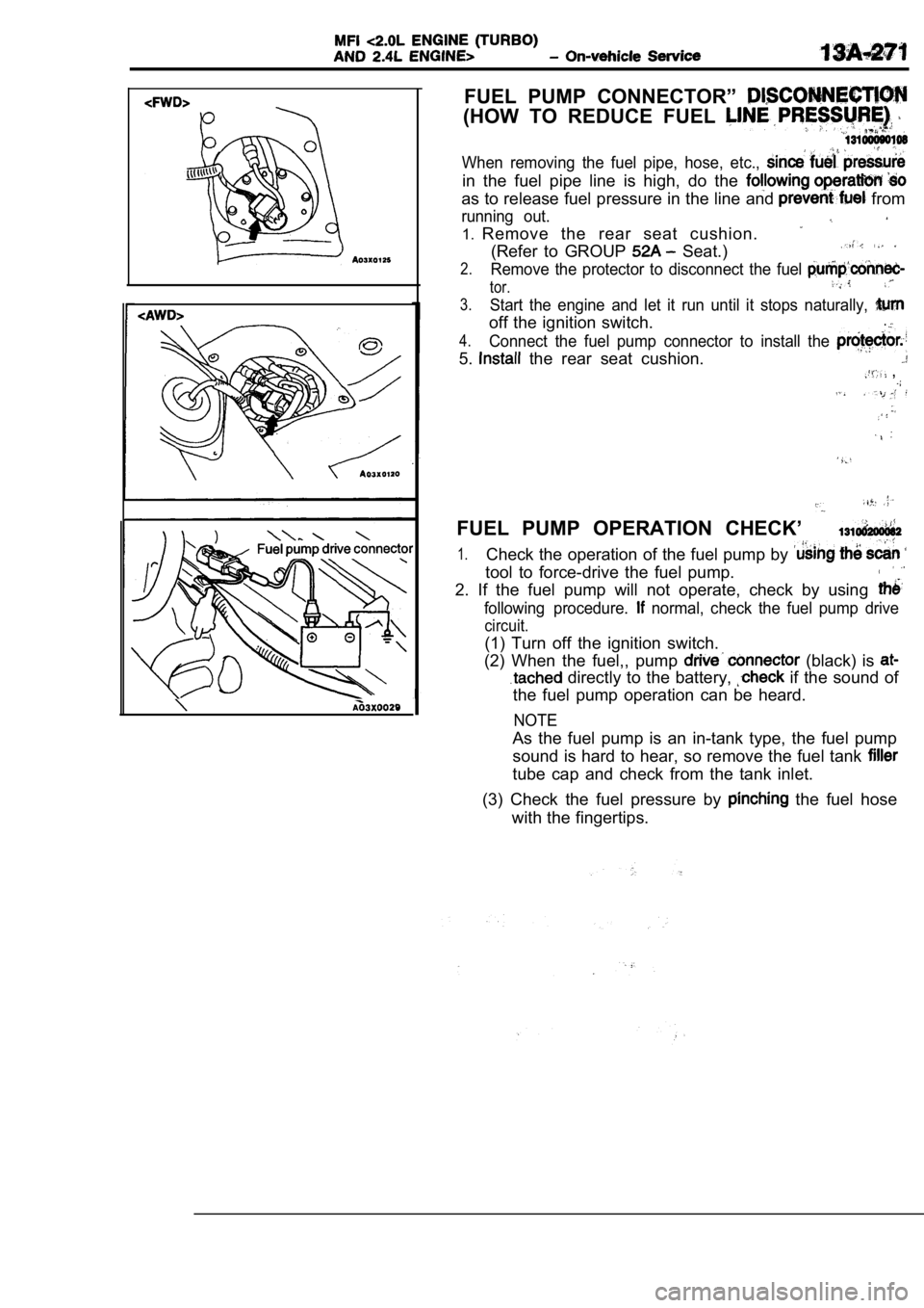
FUEL PUMP CONNECTOR”
(HOW TO REDUCE FUEL
When removing the fuel pipe, hose, etc.,
in the fuel pipe line is high, do the
as to release fuel pressure in the line and from
running out.
1.Remove the rear seat cushion.
(Refer to GROUP Seat.)
2.Remove the protector to disconnect the fuel
tor.
3.Start the engine and let it run until it stops natu rally,
off the ignition switch..
4.Connect the fuel pump connector to install the
5. the rear seat cushion. ,
FUEL PUMP OPERATION CHECK’
1.Check the operation of the fuel pump by
tool to force-drive the fuel pump.
2. If the fuel pump will not operate, check by usin g
following procedure. normal, check the fuel pump drive
circuit.
(1) Turn off the ignition switch.
(2) When the fuel,, pump
(black) is
directly to the battery, if the sound of
the fuel pump operation can be heard.
NOTE
As the fuel pump is an in-tank type, the fuel pump
sound is hard to hear, so remove the fuel tank
tube cap and check from the tank inlet.
(3) Check the fuel pressure by
the fuel hose
with the fingertips.
Page 652 of 2103
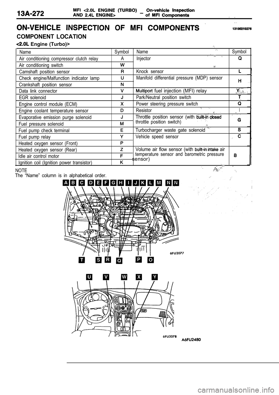
COMPONENT LOCATION
Engine (Turbo)>
Name
Air conditioning compressor clutch relay
Air conditioning switch Camshaft position sensor
Check engine/Malfunction indicator lamp
Crankshaft position sensor Data link connector
EGR solenoid
Engine control module (ECM)
Engine coolant temperature sensor
Evaporative emission purge solenoid
Fuel pressure solenoid
Fuel pump check terminal
Fuel pump relay
Heated oxygen sensor (Front)
Heated oxygen sensor (Rear)
Idle air control motor Ignition coil (Ignition power transistor)
NOTESymbol NameSymbol
A Injector
Knock sensor
Manifold differential pressure (MDP) sensor
fuel injection (MFI) relay
Park/Neutral position switch
Power steering pressure switch
ResistorI.
Throttle position sensor (with
throttle position switch)
Turbocharger waste gate solenoid
Vehicle speed sensor
Volume air flow sensor (with air
temperature sensor and barometric pressure
sensor)
.
The “Name” column is in alphabetical order.