1990 MITSUBISHI SPYDER fuel pump
[x] Cancel search: fuel pumpPage 3 of 2103
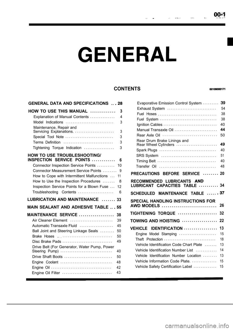
CONTENTS
GENERAL DATA AND SPECIFICATIONS. .
HOW TO USE THIS MANUAL. . . . . . . . . . . . .3
Explanation of Manual Contents. . . . . . . . . . . . . .4
Model Indications
. . . . . . . . . . . . . . . . . . . . . . . . . . .3
Maintenance, Repair and
Servicing Explanations. . . . . . . . . . . . . . . . . . . . . . .
3
Special Tool Note. . . . . . . . . . . . . . . . . . . . . . . . . . .3
Terms Definition. . . . . . . . . . . . . . . . . . . . . . . . . . . .3
Tightening Torque Indication. . . . . . . . . . . . . . . . .3
HOW TO USE TROUBLESHOOTING/
INSPECTION SERVICE POINTS. . . . . . . . . . . .6
Connector Inspection Service Points
. . . . . . . . . .10
Connector Measurement Service Points . . . . . . . .9
How to Cope with Intermittent Malfunctions . . .11
How to Use the Inspection Procedures
. . . . . . .
8
Inspection Service Points for a Blown Fuse . . .
12
Troubleshooting Contents. . . . . . . . . . . . . . . . . . . .6
LUBRICATION AND MAINTENANCE . . . . . . .33
MAIN SEALANT AND ADHESIVE TABLE
. .
MAINTENANCE SERVICE. . . . . . . . . . . . . . . . . .38
Air Cleaner Element. . . . . . . . . . . . . . . . . . . . . . . .39
Automatic Transaxle Fluid
. . . . . . . . . . . . . . . . . . .45
Ball Joint and Steering Linkage Seals
. . . . . . . .50
Brake Hoses.... . . . . . . . . . . . . . . . . . . . . . . . . . . .50
Disc Brake Pads. . . . . . . . . . . . . . . . . . . . . . . . . . . .49
Drive Belt (For Generator, Water Pump, Power
Steering Pump). . . . . . . . . . . . . . . . . . . . . . . . . . . . .40
Drive Shaft Boots
. . . . . . . . . . . . . . . . . . . . . . . . . . .50
Engine Coolant. . . . . . . . . . . . . . . . . . . . . . . . . . . . .48
Engine Oil. . . . . . . . . . . . . . . . . . . . . . . . . . . . . . . . . .42
Engine Oil Filter. . . . . . . . . . . . . . . . . . . . . . . . . . . .43
Evaporative Emission Control System . . . . . . . . .
Exhaust System. . . . . . . . . . . . . . . . . . . . . . . . . . . . .54
Fuel Hoses. . . . . . . . . . . . . . . . . . . . . . . . . . . . . . . . .38
Fuel System. . . . . . . . . . . . . . . . . . . . . . . . . . . . . . . .38
Ignition Cables. . . . . . . . . . . . . . . . . . . . . . . . . . . . . .
40
Manual Transaxle Oil . . . . . . . . . . . . . . . . . . . . . . . .
Rear Axle Oil. . . . . . . . . . . . . . . . . . . . . . . . . . . .
50
Rear Drum Brake Linings and
Rear Wheel Cylinders . . . . . . . . . . . . . . . . . . . . . . .
Spark Plugs. . . . . . . . . . . . . . . . . . . . . . . . . . . . . . . .40
SRS System . . . . . . . . . . . . . . . . . . . . . . . . . . . . . . .51
Timing Belt. . . . . . . . . . . . . . . . . . . . . . . . . . . . . . . . .40
Transfer Oil. . . . . . . . . . . . . . . . . . . . . . . . . . . . . . . .48
PRECAUTIONS BEFORE SERVICE. . . . . . . .20
RECOMMENDED LUBRICANTS
LUBRICANT CAPACITIES TABLE. . . . . . . . . .34
SCHEDULED MAINTENANCE TABLE. . . . .
SPECIAL HANDLING INSTRUCTIONS FOR
AWD MODELS . . . . . . . . . . . . . . . . . . . . . . . . . . . .
26
TIGHTENING TORQUE. . . . . . . . . . . . . . . . . . . .32
TOWING AND HOISTING . . . . . . . . . . . . . . . . . .22
VEHICLE IDENTIFICATION. . . . . . . . . . . . . . . . .13
Engine Model Stamping. . . . . . . . . . . . . . . . . . . . .15
Theft Protection. . . . . . . . . . . . . . . . . . . . . . . . . . . . .18
Vehicle Identification Code Chart Plate
. . . . . . .13
Vehicle Identification Number List. . . . . . . . . . . .14
Vehicle Identification Number Location. . . . . . . .13
Vehicle Information Code Plate.. . . . . . . . . . . . . .15
Vehicle Safety Certification Label
. . . . . . . . . . . . .15
Page 76 of 2103
ENGINE Engine
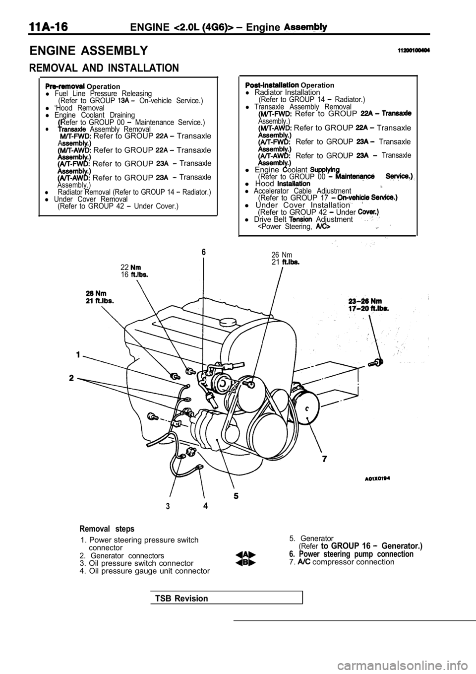
ENGINE ASSEMBLY
REMOVAL AND INSTALLATION
Operationl Fuel Line Pressure Releasing(Refer to GROUP On-vehicle Service.)l ‘Hood Removall Engine Coolant DrainingRefer to GROUP 00 Maintenance Service.)l Assembly Removal Refer to GROUP TransaxleA Refer to GROUP Transaxle
Refer to GROUP Transaxle
Refer to GROUP TransaxleAssembly.)lRadiator Removal (Refer to GROUP 14 Radiator.)l Under Cover Removal (Refer to GROUP 42 Under Cover.)
6
2216
Operationl Radiator Installation(Refer to GROUP 14 Radiator.)l Transaxle Assembly Removal Refer to GROUP Assembly.) Refer to GROUP Transaxle
Refer to GROUP Transaxle
Refer to GROUP
Transaxle
l Engineoolant(Refer to GROUP 00 l Hoodl Accelerator Cable Adjustment(Refer to GROUP 17 l Under Cover Installation(Refer to GROUP 42 Under l Drive Belt Adjustment
34
Removal steps
1. Power steering pressure switchconnector
2. Generator connectors
3. Oil pressure switch connector
4. Oil pressure gauge unit connector
5. Generator(Referto GROUP 16 Generator.)
6. Power steering pump connection7. compressor connection
TSB Revision
Page 105 of 2103
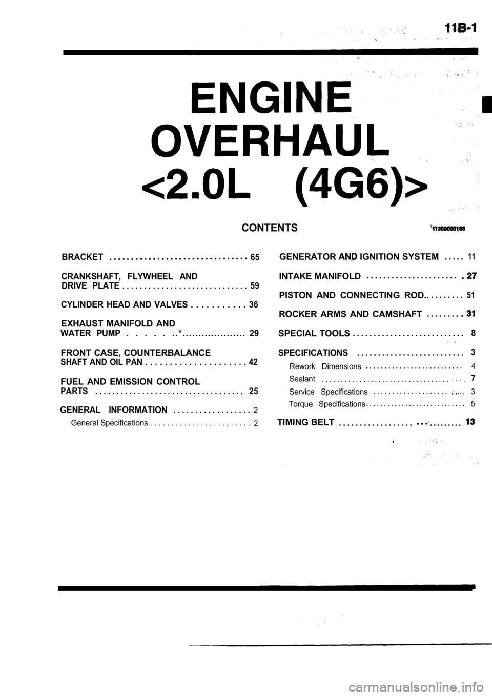
CONTENTS
BRACKET65
CRANKSHAFT, FLYWHEEL ANDDRIVE PLATE
. . . . . . . . . . . . . . . . . . . . . . . . . . . . .59
CYLINDER HEAD AND VALVES . . . . . . . . . . . 36
EXHAUST MANIFOLD AND
WATER PUMP. . . . . . . * . . . . . . . . . . . . . . . . . . . .29
FRONT CASE, COUNTERBALANCE
SHAFT AND OIL PAN . . . . . . . . . . . . . . . . . . . . . 42
FUEL AND EMISSION CONTROL
PARTS. . . . . . . . . . . . . . . . . . . . . . . . . . . . . . . . . . .25
GENERAL INFORMATION. . . . . . . . . . . . . . . . . .2
General Specifications . . . . . . . . . . . . . . . . . . , . . . . .2
GENERATOR IGNITION SYSTEM. . . . .11
INTAKE MANIFOLD. . . . . . . . . . . . . . . . . . . . . .
PISTON AND CONNECTING ROD..
. . . . . . . .51
ROCKER ARMS AND CAMSHAFT. . . . . . . .
SPECIAL TOOLS
. . . . . . . . . . . . . . . . . . . . . . . . . . .8
SPECIFICATIONS. . . . . . . . . . . . . . . . . . . . . . . . . .3
Rework Dimensions. . . . . . . . . . . . . . . . . . . . . . . . . .4
Sealant. . . . . . . . . . . . . . . . . . . . . . . . . . . . . . . . . .. . ..
Service Specifications. . . . . . . . . . . . . . . . . . . ....3
Torque Specifications. . . . . . . . . . . . . . . . . . . . . . . . . . . .5
TIMING BELT
. . . . . . . . . . . . . . . . . .. . . . . . . . .
,
Page 106 of 2103
ENGINE OVERHAUL General Information
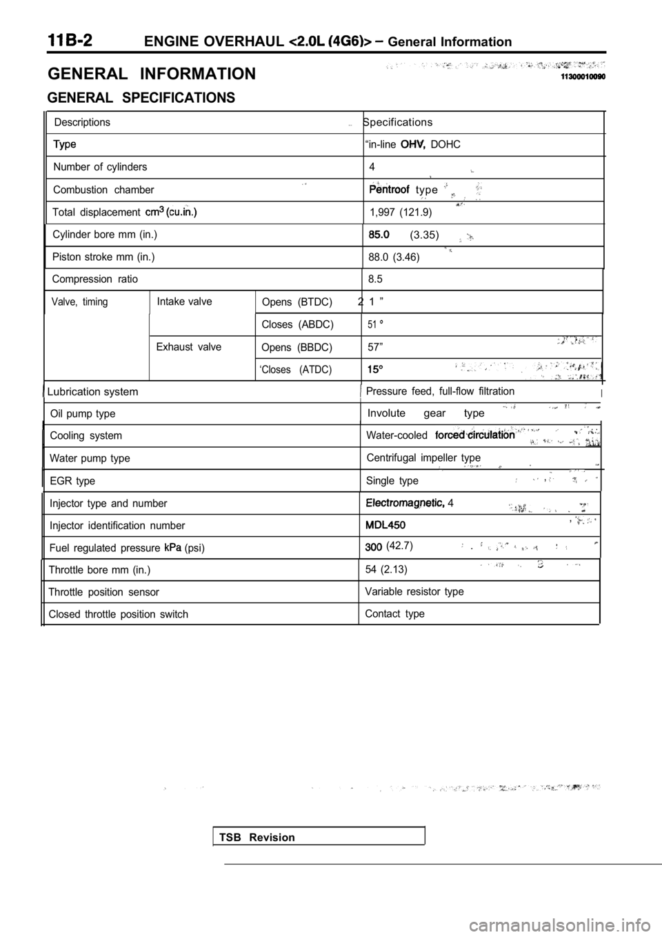
GENERAL INFORMATION
GENERAL SPECIFICATIONS
Descriptions
Number of cylinders
Combustion chamber
Total displacement
. . .Specifications
“in-line DOHC
4
type
1,997 (121.9)
Cylinder bore mm (in.)
Piston stroke mm (in.)
(3.35)
88.0 (3.46)
Compression ratio 8.5
Valve, timingIntake valve
Opens (BTDC)2 1 ”
Exhaust valve Closes (ABDC)
51
Opens (BBDC)
57”
‘Closes (ATDC)
Lubrication system Pressure feed, full-flow filtrationI
Oil pump type
Cooling system
Water pump type EGR type
I
Involute gear type
Water-cooled . .
Centrifugal impeller type
Single type,
TSB Revision
Injector type and number
Injector identification number
Fuel regulated pressure
(psi)
4
,
(42.7) .
Throttle bore mm (in.)
Throttle position sensor Closed throttle position switch 54 (2.13)
Variable resistor type
Contact type
Page 109 of 2103
ENGINE OVERHAUL
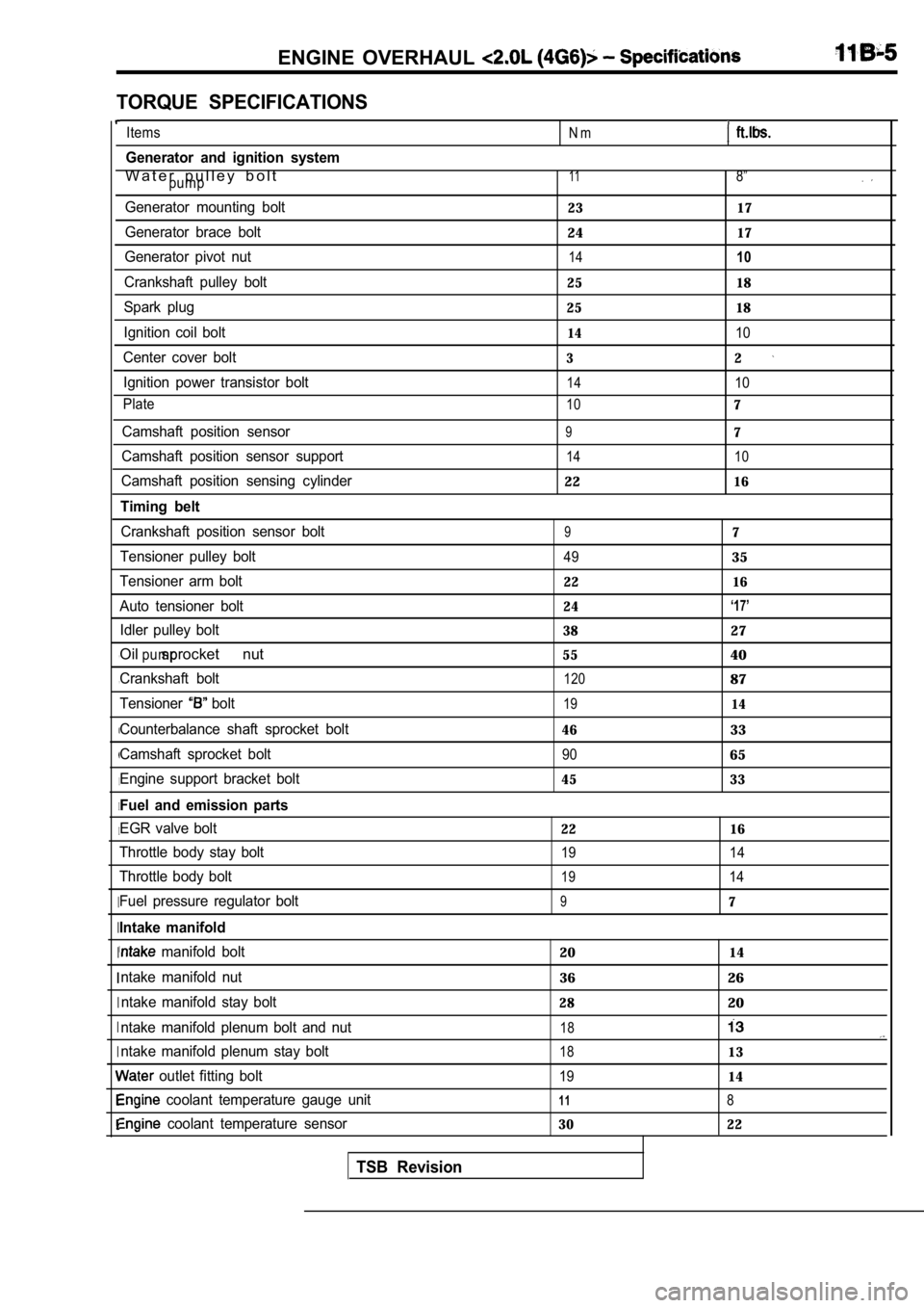
TORQUE SPECIFICATIONS
, ,
I
I I
I
I I
I
I
I I
Items
Generator and ignition system
W a t e r p u l l e y b o l tpump
Generator mounting bolt
Generator brace bolt
Generator pivot nut
Crankshaft pulley bolt
Spark plug
Ignition coil bolt
Center cover bolt Ignition power transistor bolt
Plate
Camshaft position sensor
Camshaft position sensor support
Camshaft position sensing cylinder
Timing belt
Crankshaft position sensor bolt
Tensioner pulley bolt
Tensioner arm bolt
Auto tensioner bolt Idler pulley bolt
Oil sprocket nutpump
Crankshaft bolt
Tensioner
bolt
Counterbalance shaft sprocket bolt
Camshaft sprocket bolt
Engine support bracket bolt
Fuel and emission parts
EGR valve bolt
Throttle body stay bolt
Throttle body bolt
Fuel pressure regulator bolt
Intake manifold
manifold bolt
ntake manifold nut ntake manifold stay bolt
ntake manifold plenum bolt and nut
ntake manifold plenum stay bolt
outlet fitting bolt
coolant temperature gauge unit
coolant temperature sensor
TSB Revision
N m
118”
23 17
2417
1410
25 18
25 18
1410
32
1410
107
97
14 10
2216
97
4935
22 16
24
‘17’
3827
5540
12087
1914
4633
9065
45 33
22 16
19 14
1914
97
2014
3626
2820
18
1813
1914
118
30 22
Page 183 of 2103
ENGINE On-vehicle.’
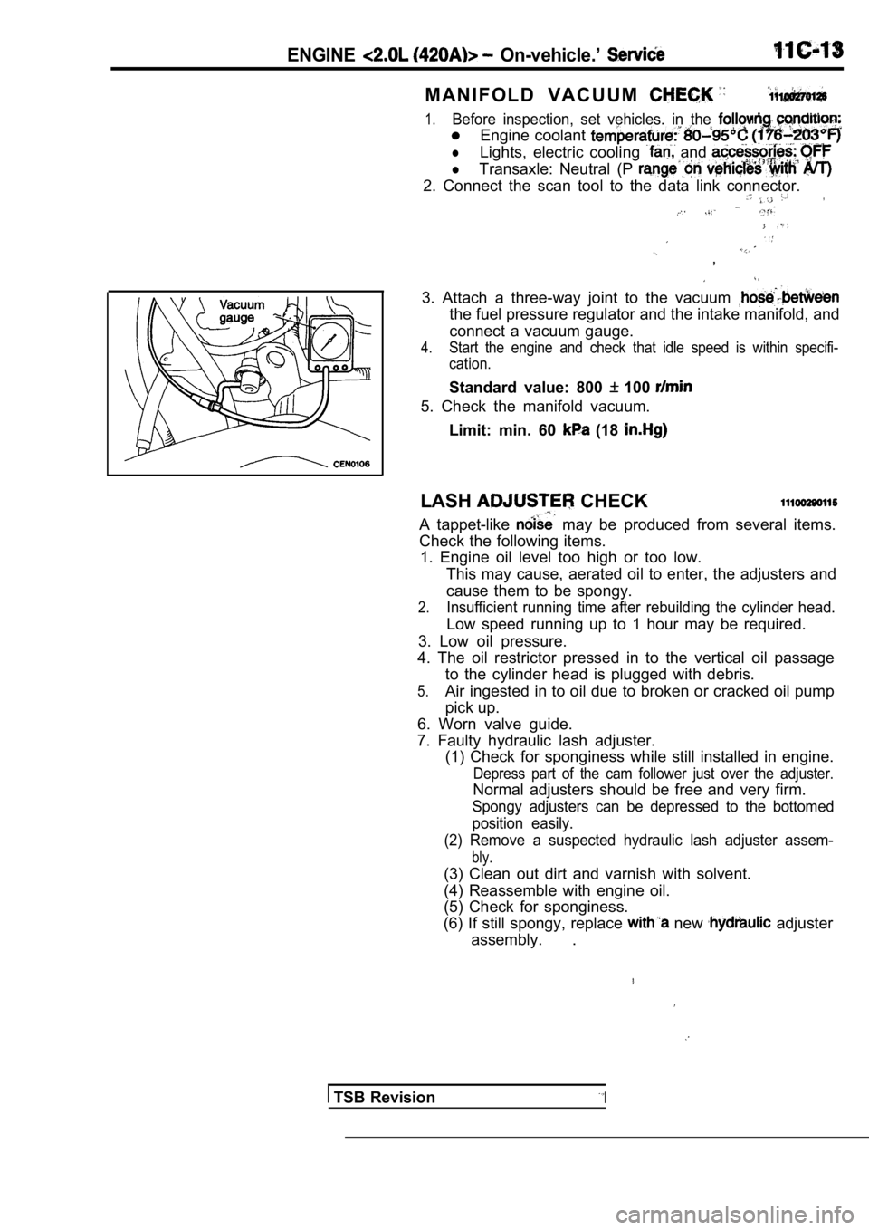
M A N I F O L D V A C U U M
1.Before inspection, set vehicles. in the condition:
Engine coolant
lLights, electric cooling and
lTransaxle: Neutral (P
2. Connect the scan tool to the data link connector.
,
3. Attach a three-way joint to the vacuum
the fuel pressure regulator and the intake manifold, and
connect a vacuum gauge.
4.Start the engine and check that idle speed is withi n specifi-
cation.
Standard value: 800 100
5. Check the manifold vacuum.
Limit: min. 60
(18
LASH CHECK
A tappet-like may be produced from several items.
Check the following items. 1. Engine oil level too high or too low.
This may cause, aerated oil to enter, the adjusters and
cause them to be spongy.
2.Insufficient running time after rebuilding the cyli nder head.
Low speed running up to 1 hour may be required.
3. Low oil pressure.
4. The oil restrictor pressed in to the vertical oi l passage
to the cylinder head is plugged with debris.
5.Air ingested in to oil due to broken or cracked oil pump
pick up.
6. Worn valve guide.
7. Faulty hydraulic lash adjuster. (1) Check for sponginess while still installed in e ngine.
Depress part of the cam follower just over the adju ster.
Normal adjusters should be free and very firm.
Spongy adjusters can be depressed to the bottomed
position easily.
(2) Remove a suspected hydraulic lash adjuster asse m-
bly.
(3) Clean out dirt and varnish with solvent.
(4) Reassemble with engine oil.
(5) Check for sponginess.
(6) If still spongy, replace
new adjuster
assembly. .
TSB RevisionI
Page 184 of 2103
ENGINE Engine
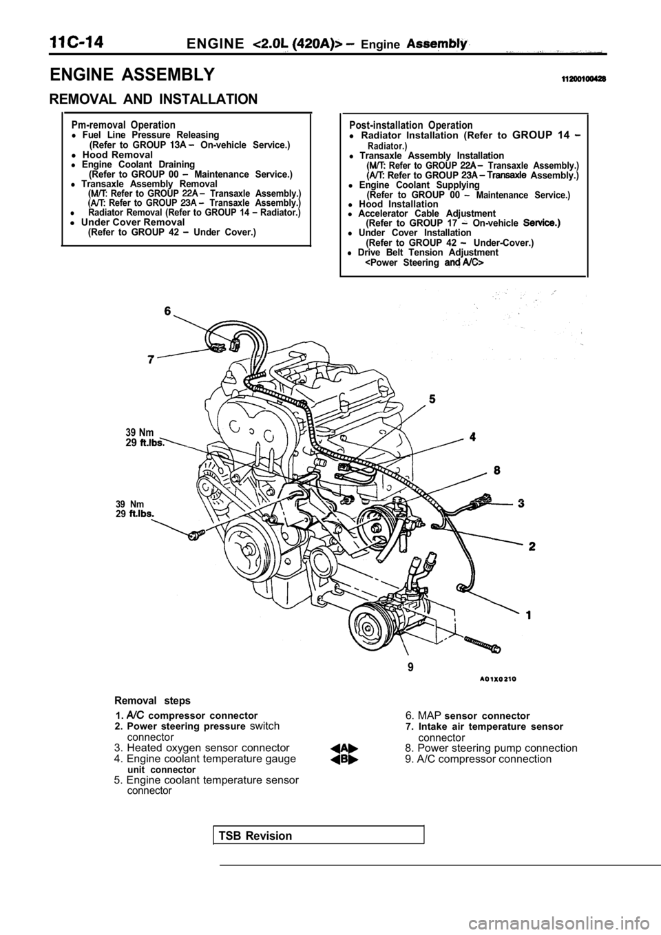
ENGINE ASSEMBLY
REMOVAL AND INSTALLATION
Pm-removal Operationl Fuel Line Pressure Releasing(Refer to GROUP On-vehicle Service.)l Hood Removall Engine Coolant Draining
(Refer to GROUP 00 Maintenance Service.)l Transaxle Assembly Removal Refer to GROUP Transaxle Assembly.) Refer to GROUP Transaxle Assembly.)lRadiator Removal (Refer to GROUP 14 Radiator.)l Under Cover Removal(Refer to GROUP 42 Under Cover.)
39 Nm29
39 Nm29
Post-installation Operationl Radiator Installation (Refer to GROUP 14 Radiator.)l Transaxle Assembly Installation Refer to GROUP Transaxle Assembly.) Refer to GROUP Assembly.)l Engine Coolant Supplying
(Refer to GROUP 00 Maintenance Service.)l Hood Installationl Accelerator Cable Adjustment(Refer to GROUP 17 On-vehicle l Under Cover Installation
(Refer to GROUP 42 Under-Cover.)l Drive Belt Tension Adjustment
Removal steps
1. compressor connector
2. Power steering pressure switch
connector3. Heated oxygen sensor connector
4. Engine coolant temperature gauge
unit connector
6. MAP sensor connector
7. Intake air temperature sensor
connector8. Power steering pump connection
9. A/C compressor connection
5. Engine coolant temperature sensor
connector
TSB Revision
Page 207 of 2103
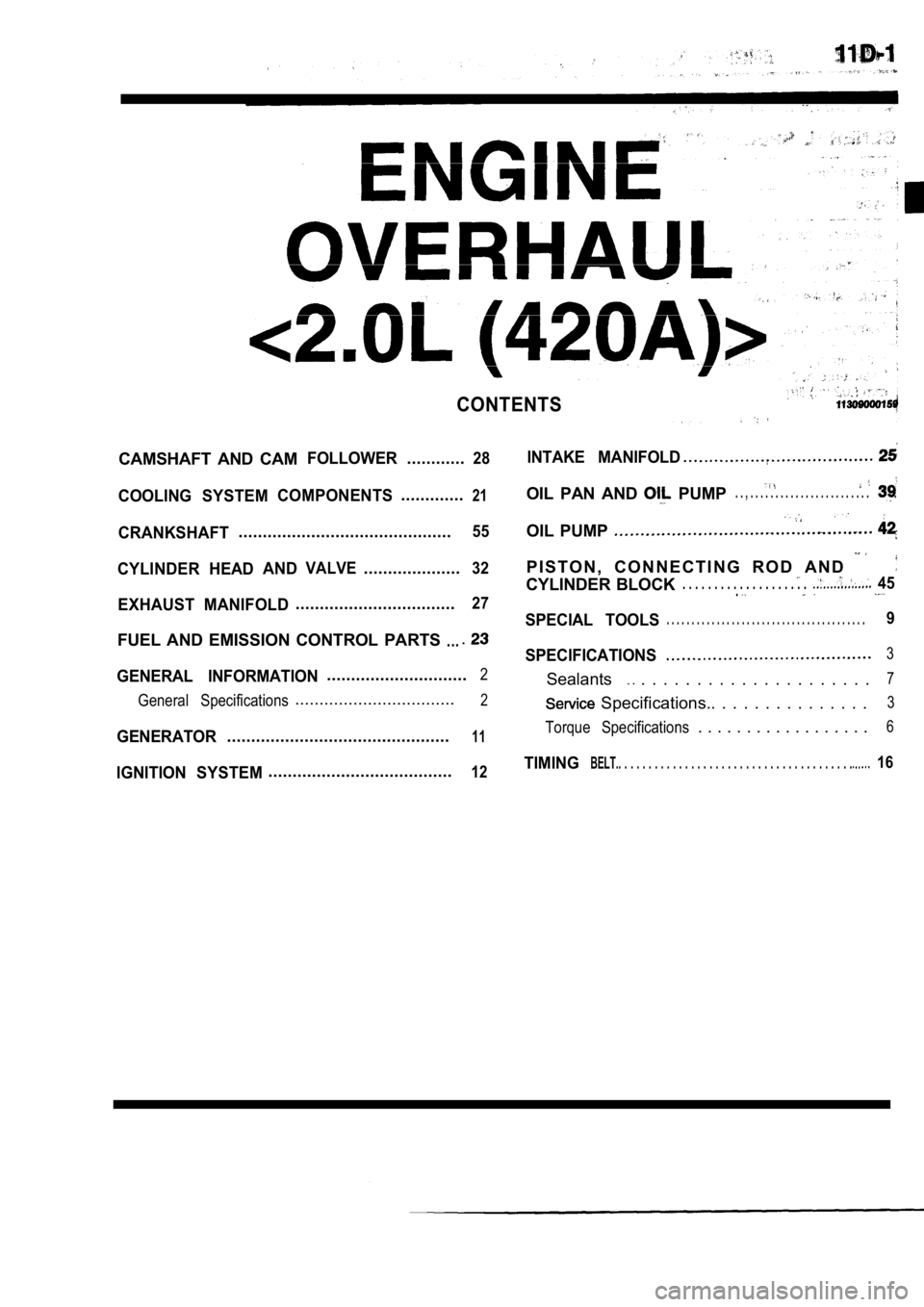
CONTENTS
CAMSHAFT AND CAMFOLLOWER............28
COOLING SYSTEMCOMPONENTS.............21
CRANKSHAFT............................................55
CYLINDER HEADANDVALVE....................32
EXHAUST MANIFOLD.................................27
FUEL AND EMISSION CONTROL PARTS...
GENERAL INFORMATION.............................2
General Specifications
.................................2
GENERATOR..............................................11
IGNITION SYSTEM......................................12
INTAKE MANIFOLD
OIL PAN AND PUMP. . , . . . . . . . . . . . . . . . . . . . . . . . . .
OIL PUMP
P I S T O N , C O N N E C T I N G R O D A N D
CYLINDER BLOCK. . . . . . . . . . . . . . . . . . . . 45.
SPECIAL TOOLS. . . . . . . . . . . . . . . . . . . . . . . . . . . . . . . . . . . . . . . .9
SPECIFICATIONS3
Sealants . . . . . . . . . . . . . . . . . . . . .7
Specifications.. . . . . . . . . . . . . . .3
Torque Specifications. . . . . . . . . . . . . . . . . .6
TIMINGBELT.. . . . . . . . . . . . . . . . . . . . . . . . . . . . . . . . . . . . . . . 16