1990 MITSUBISHI SPYDER check engine light
[x] Cancel search: check engine lightPage 812 of 2103
(Turbo) and Engine>
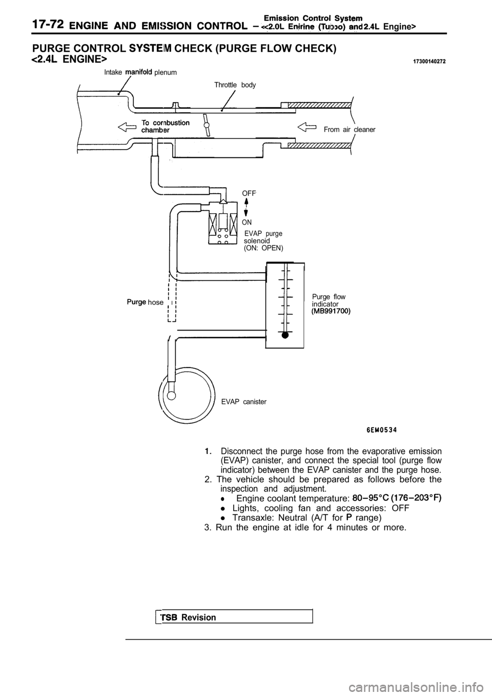
PURGE CONTROL CHECK (PURGE FLOW CHECK)
ENGINE>17300140272
IntakeplenumThrottle body
From air cleaner
OFF
ON EVAP purge
solenoid
(ON: OPEN)
hose IPurge flow
indicator
Revision
EVAP canister
Disconnect the purge hose from the evaporative emis sion
(EVAP) canister, and connect the special tool (purg e flow
indicator) between the EVAP canister and the purge hose.
2. The vehicle should be prepared as follows before the
inspection and adjustment.
lEngine coolant temperature:
l Lights, cooling fan and accessories: OFF
l Transaxle: Neutral (A/T for
range)
3. Run the engine at idle for 4 minutes or more.
Page 816 of 2103
AND C O N T R O L (Turbo) and Engine>
Valve
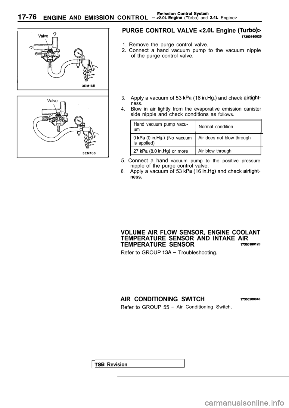
PURGE CONTROL VALVE Engine
1. Remove the purge control valve.
2. Connect a hand vacuum pump to the vacuum nipple of the purge control valve.
3.Apply a vacuum of 53 (16 and check
ness.
4.Blow in air lightly from the evaporative emission c anister
side nipple and check conditions as follows.
Hand vacuum pump vacu-
umNormal condition
0 (0 (No vacuumAir does not blow through
is applied)
27
(8.0 or more Air blow through
5. Connect a hand
vacuum pump to the positive pressure
nipple of the purge control valve.
6.Apply a vacuum of 53 (16 and check
ness.
Revision
VOLUME AIR FLOW SENSOR, ENGINE COOLANT
TEMPERATURE SENSOR AND INTAKE AIR
TEMPERATURE SENSOR
Refer to GROUP Troubleshooting.
AIR CONDITIONING SWITCH
Refer to GROUP 55 Air Conditioning Switch.
Page 820 of 2103
(Turbo) and Engine>
EXHAUST GAS RECIRCULATION
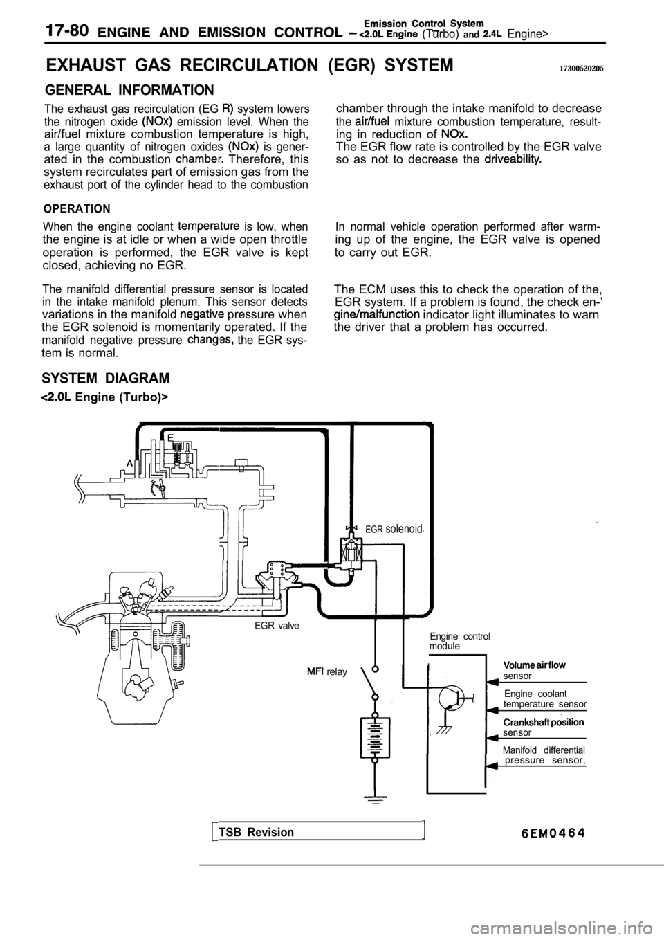
GENERAL INFORMATION
The exhaust gas recirculation (EG system lowers
the nitrogen oxide
emission level. When the
air/fuel mixture combustion temperature is high,
a large quantity of nitrogen oxides is gener-
ated in the combustion Therefore, this
system recirculates part of emission gas from the
exhaust port of the cylinder head to the combustion
OPERATION
When the engine coolant is low, when
the engine is at idle or when a wide open throttle
operation is performed, the EGR valve is kept
closed, achieving no EGR.
The manifold differential pressure sensor is locate d
in the intake manifold plenum. This sensor detects
variations in the manifold pressure when
the EGR solenoid is momentarily operated. If the
manifold negative pressure the EGR sys-
tem is normal.
SYSTEM DIAGRAM
Engine (Turbo)>
(EGR) SYSTEM17300520205
chamber through the intake manifold to decrease
the mixture combustion temperature, result-
ing in reduction of
The EGR flow rate is controlled by the EGR valve
so as not to decrease the
In normal vehicle operation performed after warm-
ing up of the engine, the EGR valve is opened
to carry out EGR.
The ECM uses this to check the operation of the, EGR system. If a problem is found, the check en-’
indicator light illuminates to warn
the driver that a problem has occurred.
EGR valve
relay
EGRsolenoid
Engine control
module
Isensor
Engine coolant
temperature sensor
sensor
Manifold differential
TSB Revision
pressure sensor,
Page 859 of 2103

CONTENTS
MANUAL TRANSAXLE ENGINEMANUAL TRANSAXLE ENGINE
(NON-TURBO)>(TURBO) AND ENGINE>
GENERAL INFORMATION . . . . . . . . . . . . . . 22GENERAL INFORMATION . . . . . . . . . . . . . . . .
2
LUBRICANTS. . . . . . . . . . . . . . . . . . . . . . . . . . 24LUBRICANTS. . . . . . . . . . . . . . . . . . . . . . . . . . .6
ON-VEHICLE SERVICE. . . . . . . . . . . . . . . . .
2 4
Transaxle Oil Level Check . . . . . . . . . . . . . . . .
24
Transaxle Oil Replacement . . . . . . . . . . . . . . .
24
SERVICE SPECIFICATIONS. . . . . . . . . . . . .24
SPECIAL TOOLS. . . . . . . . . . . . . . . . . . . . . . .24
TRANSAXLE ASSEMBLY. . . . . . . . . . . . . . .28
TRANSAXLE CONTROL*. . . . . . . . . . . . . . . .25ON-VEHICLE SERVICE
. . . . . . . . . . . . . . . . 8
Shift Lever Assembly
. . . . . . . . . . . . . . . . . . . . .
27
TROUBLESHOOTING. . . . . . . . . . . . . . . . . . .24
Transaxle Oil Level Check . . . . . . . . . . . . . . . . .8
Transaxle Oil Replacement
. . . . . . . . . . .. . .
Transfer Oil Level Check ...... . . . . . . . . . . .
Transfer Oil Replacement. . . . . . . . . . . . . . . . . .8
SERVICE SPECIFICATIONS. . . . . . . . . . ...
SPECIAL TOOLS 7. . . . . . . . . . . . . . . . . .
TRANSAXLE ASSEMBLY
. . . . . . . . . . . . . . . . . . . . ... . . .
. . . . . . . . . . . . . . . . . . . . . . . . . . . .
. . 1 2
TRANSAXLE CONTROL*... . . . . . . . .
Shift Lever Assembly. . . . . . . . . . . . . . . . . . . . . .1 1
TRANSFER ASSEMBLY . . . . . . . .
TROUBLESHOOTING . . . . . . . . . . . . . . . . . .
WARNINGS REGARDING SERVICING OF SUPPLEMENTAL RESTRA
INT SYSTEM (SRS) EQUIPPED VEHICLES
WARNING!
(1)Improper service or maintenance of any component of the or any component, can lead to personalinjury or death to service personnel (from inadvertent firing of the air bag) or to the driver and passenger (from
rendering the inoperative).Service or maintenance of any or component must be performed only at an authorized MITSUBISHI dealer.(3)MITSUBISHI dealer personnel must thoroughly review this manual,and especially its GROUP
Restraint System and GROUP 00 Maintenance Service, before beginning any or maintenance of
any component of the or any component.
NOTEThe SRS includes the following components: warning light, air bag module,clock spring, and interconnecting
wiring. Other
components (that may have to be removed/installed in connection with service or maintenance)
are indicated in the table of contents by an asterisk
Page 870 of 2103
MANUAL TRANSAXLE
ENGINE AND ENGINE> Transaxle
TRANSAXLE
REMOVAL AND INSTALLATION
Pre-removal Operationl Transaxle Oil Draining (Refer to GROUP 00 Maintenance Service.)l Removal
l Under Cover Removal
(Refer to GROUP 42
Under Cover.)
Engine>
Post-installation Operationl Supplying Transaxle Oil (Refer to GROUP 00 Maintenance Service.)l Shift Lever Operation Check
l Speedometer Operation Check
l Under Cover Installation
(Refer to GROUP 42
Under Cover.)
l Battery installation
56
6942
Engine (Turbo)>51
32
6
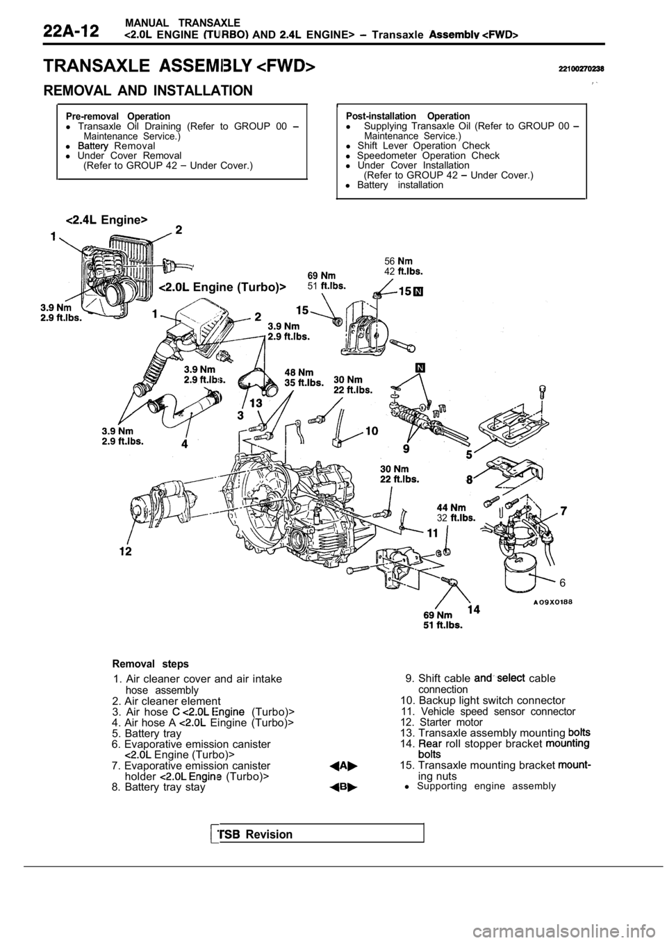
Removal steps
1. Air cleaner cover and air intake
hose assembly2. Air cleaner element
3. Air hose (Turbo)>
4. Air hose A Eingine (Turbo)>
5. Battery tray
6. Evaporative emission canister
Engine (Turbo)>
7. Evaporative emission canister holder
(Turbo)>
8. Battery tray stay 9. Shift cable
cableconnection10. Backup light switch connector11. Vehicle speed sensor connector
12. Starter motor
13. Transaxle assembly mounting 14. roll stopper bracket
15. Transaxle mounting bracket ing nuts
l Supporting engine assembly
Revision
Page 874 of 2103
MANUAL ,
ENGINE AND Transaxle Assembly .
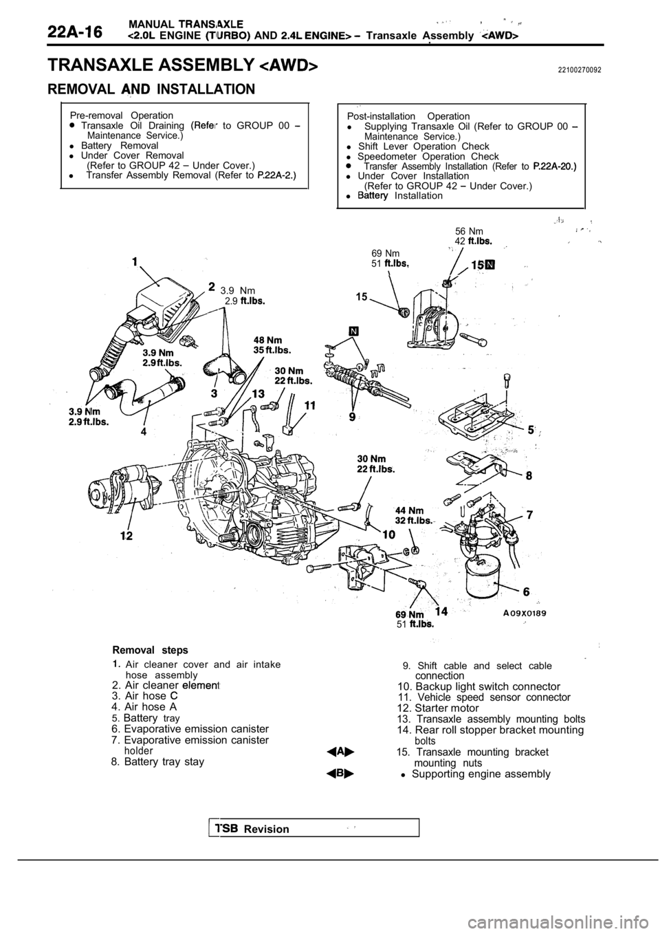
TRANSAXLE ASSEMBLY
REMOVAL INSTALLATION
22100270092
Pre-removal Operation
Transaxle Oil Draining to GROUP 00 Maintenance Service.)l Battery Removal
l Under Cover Removal
(Refer to GROUP 42
Under Cover.)
l Transfer Assembly Removal (Refer to
3.9 Nm
4
2.9
Post-installation Operation
l Supplying Transaxle Oil (Refer to GROUP 00
Maintenance Service.)l Shift Lever Operation Check
l Speedometer Operation Check
Transfer Assembly Installation (Refer to l Under Cover Installation
(Refer to GROUP 42 Under Cover.)
l Installation
69 Nm
51
56 Nm
42
15
51
Removal steps
Air cleaner cover and air intake
hose assembly
2. Air cleaner
3. Air hose 4. Air hose A
5. Battery tray
6. Evaporative emission canister
7. Evaporative emission canister
holder8. Battery tray stay 9. Shift cable and select cable
connection10. Backup light switch connector11. Vehicle speed sensor connector12. Starter motor13. Transaxle assembly mounting bolts14. Rear roll stopper bracket mountingbolts
15. Transaxle mounting bracket
mounting nuts
l Supporting engine assembly
Revision
Page 886 of 2103
MANUAL TRANSAXLE
ENGINE (NON-TURBO)> Transaxle Control
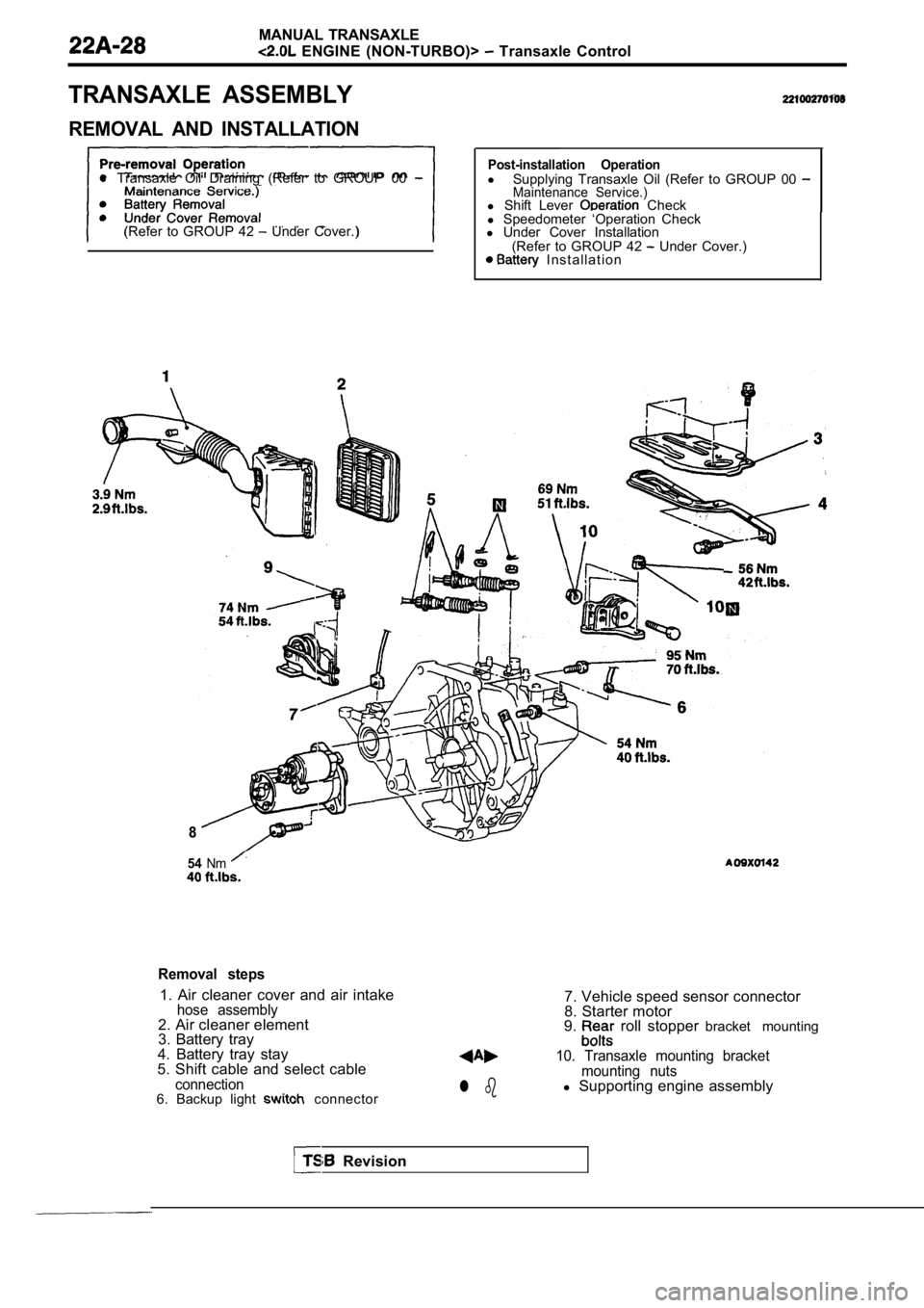
TRANSAXLE ASSEMBLY
REMOVAL AND INSTALLATION
l Transaxle Oil Draining (Refer to GROUP 00
(Refer to GROUP 42 Under Cover.)
Post-installation Operationl
Supplying Transaxle Oil (Refer to GROUP 00 Maintenance Service.)l Shift Lever Check
l Speedometer ‘Operation Check
l Under Cover Installation
(Refer to GROUP 42
Under Cover.) I n s t a l l a t i o n
8
54Nm
Removal steps
1. Air cleaner cover and air intakehose assembly2. Air cleaner element
3. Battery tray
4. Battery tray stay
5. Shift cable and select cable
connection6. Backup light connectorl b
7. Vehicle speed sensor connector
8. Starter motor
9.
roll stopper bracket mounting
10. Transaxle mounting bracket
mounting nuts
l Supporting engine assembly
Revision
Page 1009 of 2103
CONTENTS
AUTOMATIC TRANSAXLE
ENGINE (NON-TURBO)> . . . . . 115
AUTOMATIC TRANSAXLE KEY INTERLOCK
AND SHIFT LOCK MECHANISMS* . . . . . . . . 192
GENERAL INFORMATION
. . . . . . . . . . . . . . . . 115
LUBRICANTS. . . . . . . . . . . . . . . . . . . . . . . . . . . .117
ON-VEHICLE SERVICE . . . . . . . . . . . . . . . . . . . 159
Automatic Transaxle Control Component
Oil Temperature Sensor Continuity Check . . . . 160
Pinion Factor Writing Procedure After
TCM Replacement or Tire Size Change
. . . 159
Selector Level Operation Check . . . . . . . . . . . . . . ,166
Shift Lock Mechanism Check. . . . . . . . . . . . . . .
1 8 6
TCM Resetting Procedure . . . . . . . . . . . . .
..159
Torque Converter Stall Testing. . . . . . . . . . . . . .166
Transaxle Fluid Level Check . . . . . . . . . . .. . .159
Transaxle Fluid Replacement. . . . . . . . . . . . . . .
Transaxle Range Sensor Continuity . . .
Check. . . . . . . . . . . . . . . . . . . . . . . . . . . . . . . . . . . .163SERVICE SPECIFICATIONS.. . . .. . .Automatic Transaxle Control Component Layout
. . . . . . . . . . . . . . . . . . . . . . . . . . . . . . . . . . . . . . . . . . .
161SPECIAL TOOLS. . . . . . . . . . . . . . . . . . . . . . . . .117Clutch Air Pressure Tests . . . . . . . . . . . . . . . . . . .168
Fluid Leakage-Torque Converter Housing Area
Check. . . . . . . . . . . . . . . . . . . . . . . . . . . . . . . . . . . .169
Hydraulic Pressure Tests. . . . . . . . . . . . . . . . . . .169
Hydraulic Circuit. . . . . . . . . . . . . . . . . . . . . . . . . . .173
TRANSAXLE ASSEMBLY. . . . . . . . . . . . . . . .
TRANSAXLE CONTROL*. . . . . . . . . . . . . . . . .187
Selector Lever Assembly. . . . . . . . . . . . . . . . . . .189
Key Interlock Mechanism Check . . . . . . . . . . .
. 186CONTINUED ON NEXT PAGE
WARNINGS REGARDING SERVICING OF SUPPLEMENTAL EQUIPPED VEHICLES
WARNING! (1) Improper service or maintenance of any componen t of the
or any component, can lead to personal
injuryordeath inadvertent the inoperative).
(2) Service or maintenance of any component or SRS-related component must be perform ed only at an authorized
MITSUBISHI dealer.
(3)MITSUBISHI dealer personnel must thoroughly review this manual, and especially its GROUP Supplemental Re-
straint System (SRS) and GROUP 00 -Maintenance Serv ice before beginning any service or maintenance of any com-
ponent of the
or any component.
NOTEThe SRS includes the following components: SRS-ECU, SRS warning light, air bag module, clockspring and inte rconnecting wiring.Other SRS-related components (that may have to be removed/installed in connection with SRS service or maintenance) are indi-cated in the table of contents by an asterisk