Page 775 of 2103
ENGINE AND EMISSION CONTROL Auto-cruise Control System
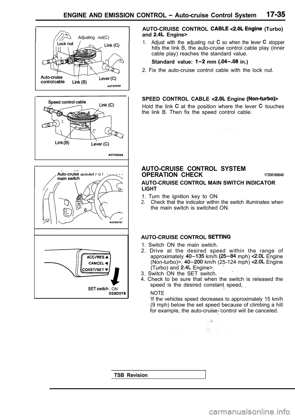
Adjusting nut(C)
c o n t r o l - - - - - -
ON
AUTO-CRUISE CONTROL (Turbo)
and
Engine>
1.Adjust with the adjusting nut so when the lever stopper
hits the link B, the auto-cruise control cable play (inner
cable play) reaches the standard value.
Standard value:
mm in.)
2. Fix the auto-cruise control cable with the lock nut.
SPEED CONTROL CABLE
Engine
Hold the link at the position where the lever touches
the link B. Then fix the speed control cable.
AUTO-CRUISE CONTROL SYSTEM
OPERATION CHECK
17200160048
AUTO-CRUISE CONTROL MAIN SWITCH INDICATOR
LIGHT
1. Turn the ignition key to ON
2.Check that the indicator within the switch illumina tes when
the main switch is switched ON.
AUTO-CRUISE CONTROL
1. Switch ON the main switch.
2. Drive at the desired speed within the range of approximately
km/h mph) Engine
(Non-turbo)>,
km/h (25-124 mph) Engine
(Turbo) and
Engine>.
3. Switch ON the SET switch.
4. Check to be sure that when the switch is release d the
speed is the desired constant speed,
.
NOTE
‘If the vehicles speed decreases to approximately 1 5 km/h
(9 mph) below the set speed because of climbing a h ill
for example, the auto-cruise-‘control will be cance led.
TSB Revision
Page 776 of 2103
17-36ENGINE AND EMISSION CONTROL Auto-cruise Control System
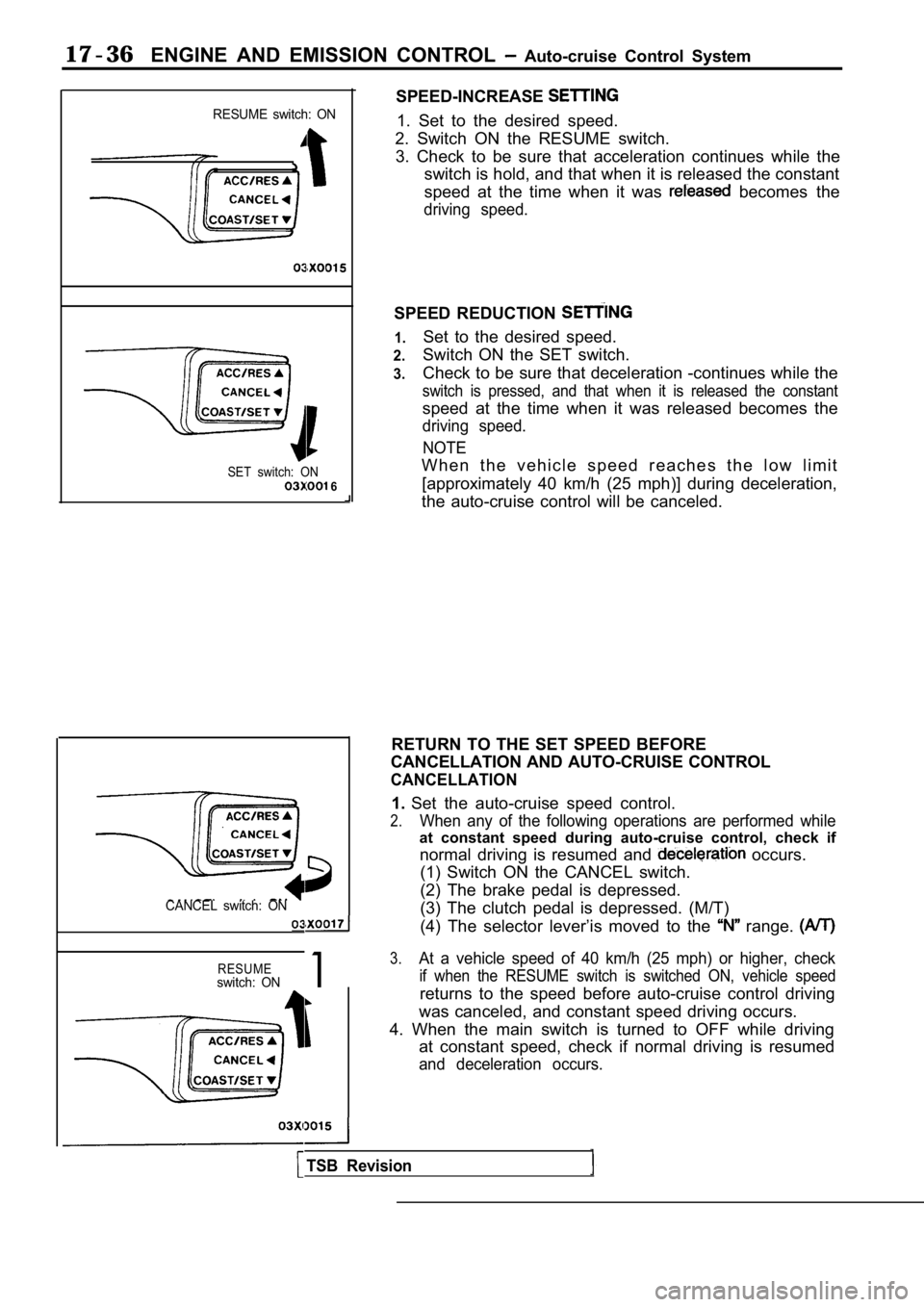
RESUME switch: ON
SET switch: ON 6
CANCEL switch: ON
RESUMEswitch: ON1
SPEED-INCREASE
1. Set to the desired speed.
2. Switch ON the RESUME switch. 3. Check to be sure that acceleration continues whi le the
switch is hold, and that when it is released the co nstant
speed at the time when it was
becomes the
driving speed.
SPEED REDUCTION
1.
2.
3.
Set to the desired speed.
Switch ON the SET switch.
Check to be sure that deceleration -continues while the
switch is pressed, and that when it is released the constant
speed at the time when it was released becomes the
driving speed.
NOTE
W h e n t h e v e h i c l e s p e e d r e a c h e s t h e l o w l i m i t[approximately 40 km/h (25 mph)] during deceleratio n,
the auto-cruise control will be canceled.
RETURN TO THE SET SPEED BEFORE
CANCELLATION AND AUTO-CRUISE CONTROL
CANCELLATION
1. Set the auto-cruise speed control.
2.When any of the following operations are performed while
at constant speed during auto-cruise control, check if
normal driving is resumed and
occurs.
(1) Switch ON the CANCEL switch.
(2) The brake pedal is depressed.
(3) The clutch pedal is depressed. (M/T)
(4) The selector lever’is moved to the
range.
3.At a vehicle speed of 40 km/h (25 mph) or higher, c heck
if when the RESUME switch is switched ON, vehicle s peed
returns to the speed before auto-cruise control driving
was canceled, and constant speed driving occurs.
4. When the main switch is turned to OFF while driv ing
at constant speed, check if normal driving is resum ed
and deceleration occurs.
TSB Revision
Page 777 of 2103
ENGINE AND EMISSION CONTROL Auto-cruise Control System
CONTROL COMPONENT
STOP LIGHT SWITCH
MeasurementFor stop lightFor
conditionscircuitcontrol circuit
terminal No.
terminal
2314
When brake pedal
depressed.0
When brake pedal notdepressed.0 0
CLUTCH PEDAL POSITION SWITCH
Engine (Turbo) and Engine
Measurement conditions
When clutch pedal depressed.Terminal No.
12
0
When clutch pedal not depressed.
PARK/NEUTRAL POSITION SWITCH POSITION)
Engine (Turbo) and Engine>
Measurement Terminal No.Iconditions Engine (Turbo)7 8I
Engine
Selector lever is not at position
Selector lever is at
position 5
8
0
AUTO-CRUISE VACUUM PUMP (Turbo)
and
Engine>
1. Disconnect the vacuum hose from
vacuum
pump and connect a vacuum the vacuum pump.
2. Disconnect the electric vacuum pump connector.
TSB Revision
Page 778 of 2103
17-38ENGINE AND EMISSION CONTROL Auto-cruise’ Control
closed>
II
I
Battery
0 0 0 0 0 2 6 4
35 mm (1.38 in.) or more
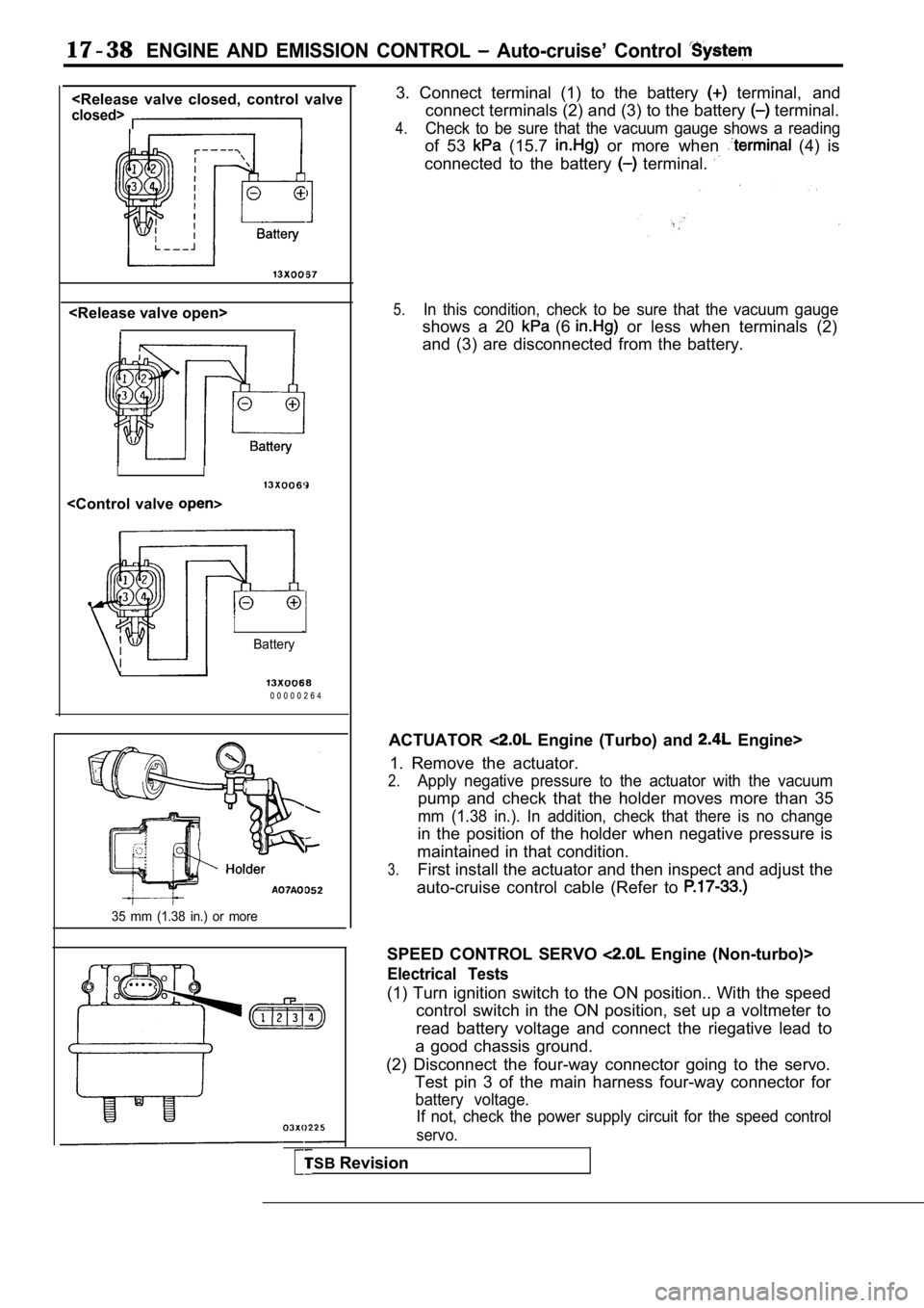
3. Connect terminal (1) to the battery terminal, and
connect terminals (2) and (3) to the battery
terminal.
4.Check to be sure that the vacuum gauge shows a read ing
of 53 (15.7 or more when (4) is
connected to the battery
terminal.
5.In this condition, check to be sure that the vacuum gauge
shows a 20 (6 or less when terminals (2)
and (3) are disconnected from the battery.
ACTUATOR
Engine (Turbo) and Engine>
1. Remove the actuator.
2.Apply negative pressure to the actuator with the va cuum
pump and check that the holder moves more than 35
mm (1.38 in.). In addition, check that there is no change
in the position of the holder when negative pressur e is
maintained in that condition.
3.First install the actuator and then inspect and adj ust the
auto-cruise control cable (Refer to
SPEED CONTROL SERVO Engine (Non-turbo)>
Electrical Tests
(1) Turn ignition switch to the ON position.. With the speed
control switch in the ON position, set up a voltmet er to
read battery voltage and connect the riegative lead to
a good chassis ground.
(2) Disconnect the four-way connector going to the servo.
Test pin 3 of the main harness four-way connector f or
battery voltage.
If not, check the power supply circuit for the spee d control
servo.
TSBRevision
Page 779 of 2103
C o n t r o l
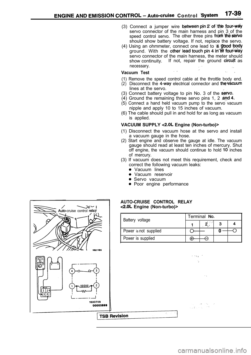
(3) Connect a jumper wire
servo connector of the main harness and pin 3 of the
speed control servo.The other three pins
should show battery voltage. If not, replace the se
rvo.
(4) Using an ohmmeter, connect one lead to
ground. With the
servo connector of the main harness, the meter shou ld
show continuity. If not, repair the ground
as
necessary. .
Vacuum Test
(1) Remove the speed control cable at the throttle
body end.
(2)Disconnect the electrical connector and
lines at the servo.
(3) Connect battery voltage to pin No. 3 of the
(4) Ground the remaining three servo pins 1, 2
(5) Connect a hand held vacuum pump to the servo va cuum
nipple and apply 10 to 15 inches of vacuum.
(6) The cable should pull in and hold for as long a s vacuum
is applied.
VACUUM SUPPLY Engine (Non-turbo)>
(1) Disconnect the vacuum hose at the servo and ins tall
a vacuum gauge in the hose.
(2) Start engine and observe the gauge at idle. The vacuum
gauge should read at least ten inches of mercury. Shut
off engine, the vacuum should continue to hold inches
of mercury.
(3) If vacuum does not meet this requirement, check and
correct the following vacuum leaks:
Vacuum lines
Vacuum reservoir
Servo vacuum
Poor engine performance
I-cruise control
AUTO-CRUISE CONTROL RELAY
Engine (Non-turbo)>
Battery voltage
Power
isnot supplied
Power is supplied
Terminal
,
,
,0
Page 780 of 2103
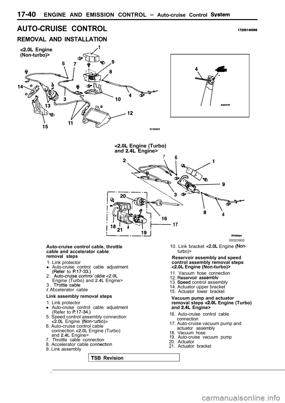
ENGINE AND EMISSION CONTROL Auto-cruise Control
AUTO-CRUISE CONTROL
REMOVAL AND INSTALLATION
Engine
(Non-turbo)>
Engine (Turbo)
and
Engine>
76
4
17
00003900
Auto-cruise control cable, throttle
cable and accelerator cable
removal steps
1. Link protectorl Auto-cruise control cable adjustment to .2 .Engine (Turbo) and Engine>
3 .
10. Link bracket Engine
turbo)>
Reservoir assembly and speed
control assembly removal steps
Engine (Non-turbo)>
11. Vacuum hose connection
4. Accelerator cable 12.
13. control assembly
14. Actuator upper bracket
Vacuum pump and actuator
15. Actuator lower bracket
Link assembly removal steps1. Link protector
l Auto-cruise control cable adjustment(Refer to 5. Speed control assembly connection Engine 6. Auto-cruise control cable connection Engine (Turbo)
and Engine>7. Throttle cable connection8. Accelerator cable 9. Link assembly removal steps
Engine (Turbo)
and Engine>
16. Auto-cruise control cable
connection
17. Auto-cruise vacuum pump andactuator assembly
18. Vacuum hose
19. Auto-cruise vacuum pump
20. Actuator
21. Actuator bracket
TSB Revision
Page 781 of 2103
ENGINE AND EMISSION CONTROL
Engine (Non-turbo)> (Turbo) and
Powertrain control module removal
steps Engine (Non-turbo)>
l Air cleaner22. Powertrain control module bracket23. Powertrain control module
Auto-cruise removalsteps Engine (Turbo) and Engine>
l side
Auto-cruise control main switch
removat steps
25. Instrument panel switch 26. Auto-cruise control main
TSB Revision
Page 782 of 2103
17-42ENGINE AND EMISSION CONTROL Auto-cruise Control System
CAUTION:Beforeremoval of air bag module and clock spring, refer t o the following sections:GROUP SRS Service Precautions.GROUP Air Bag Modules Clock Spring.
5.9 Nm4.3
41Nm30
2 8
Auto-cruise control switch and
clock spring
steps
27. Air bag module (Refer to GROUP
Bag
Modules and Clock Spring.)
28. Auto-cruise control
29. Steering wheel
30. Steering column upper cover
31. Steering column lower cover
l
under cover (Refer to
GROUP Panel.)
32. Clock spring (Refer to GROUP
Bag
Modules and Clock Spring.) 3 8
Sensor removal steps
33. Throttle position sensor
Engine (Turbo) and Engine>
34. Transaxle range switch
Engine (Non-turbo) 35. Park/neutral position switch Engine AA and Engine
36. Stop light switch
37. Clutch pedal position switch
Engine (Turbo) M/T and Engine 38. Vehicle speed sensor
Revision