1990 MITSUBISHI SPYDER cruise control
[x] Cancel search: cruise controlPage 783 of 2103
ENGINE AND EMISSION CONTROL Control
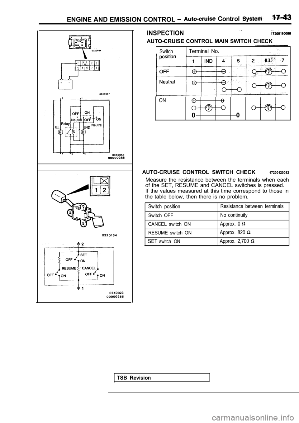
INSPECTION. .
AUTO-CRUISE CONTROL MAIN SWITCH CHECK
SwitchTerminal No.
ON0
0 0
AUTO-CRUISE CONTROL SWITCH CHECK
17200120082
Measure the resistance between the terminals when e ach
of the SET, RESUME and CANCEL switches is pressed.
If the values measured at this time correspond to t hose in
the table below, then there is no problem.
Switch position Resistance between terminals
Switch OFFNo continuity
CANCEL switch ONApprox. 0
RESUME switch ONApprox. 820
SETswitch ONApprox. 2,700
TSB Revision
Page 784 of 2103
ENGINE AND EMISSION CONTROL Auto-cruise System’,
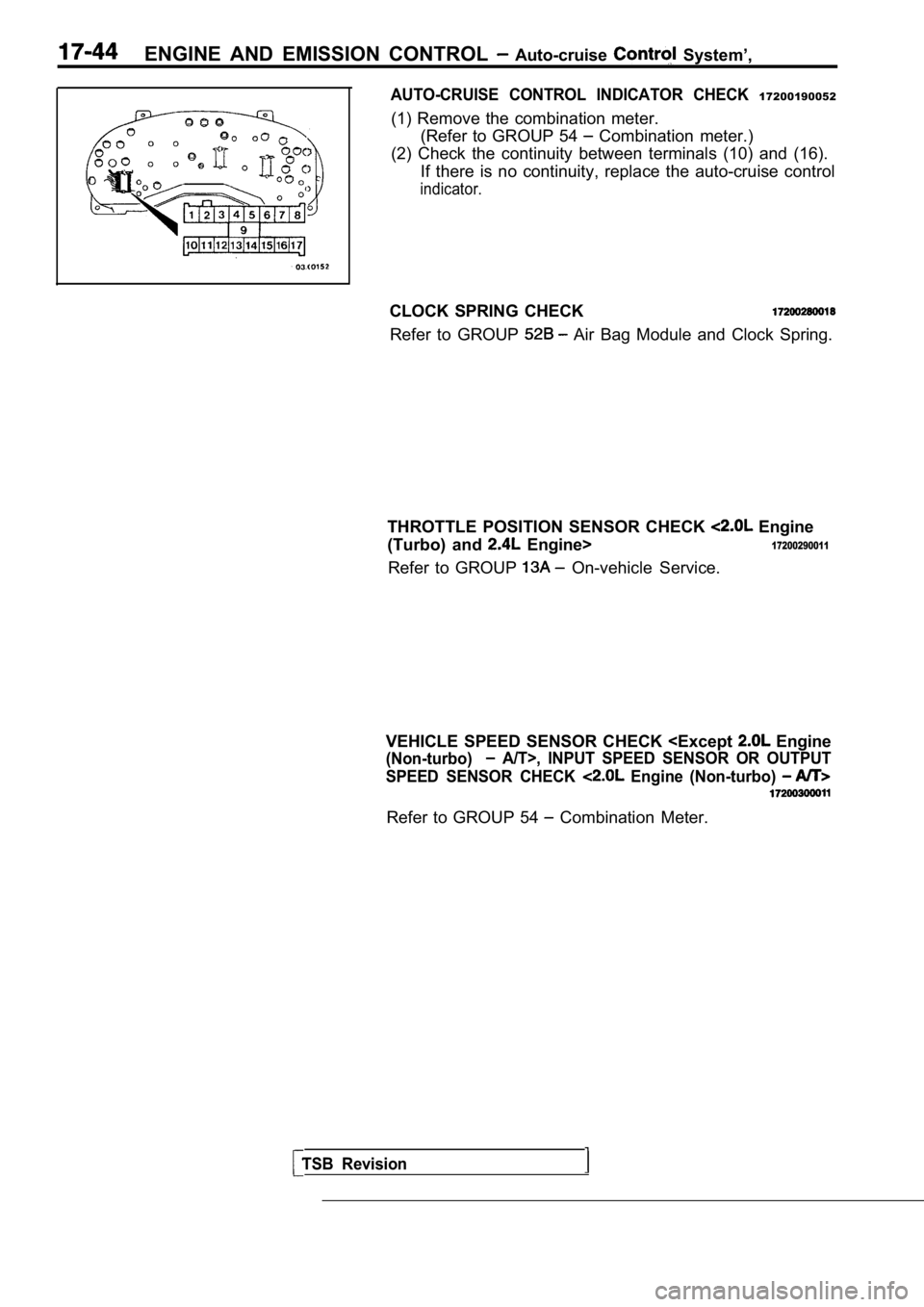
AUTO-CRUISE CONTROL INDICATOR CHECK 17200190052
(1) Remove the combination meter.(Refer to GROUP 54
Combination meter.)
(2) Check the continuity between terminals (10) and (16).
If there is no continuity, replace the auto-cruise control
indicator.
CLOCK SPRING CHECK
Refer to GROUP Air Bag Module and Clock Spring.
THROTTLE POSITION SENSOR CHECK
Engine
(Turbo) and
Engine>17200290011
Refer to GROUP On-vehicle Service.
VEHICLE SPEED SENSOR CHECK
(Non-turbo) A/T>, INPUT SPEED SENSOR OR OUTPUT
SPEED SENSOR CHECK
Engine (Non-turbo)
Refer to GROUP 54 Combination Meter.
TSB Revision
Page 835 of 2103
CLUTCH -On-vehicle Service
Pedal height
Adjusting bolt
or clutch pedal
position
switch
Clutch pedal freeDistance between theclutch pedal and thewhentheclutch is disengaged
0 0 0 0 0 0 8 9
ON-VEHICLE SERVICE21199999999
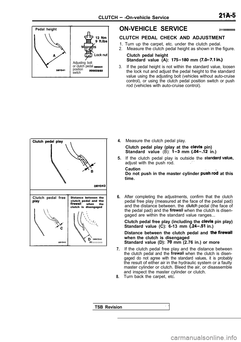
CLUTCH PEDAL CHECK AND ADJUSTMENT
1. Turn up the carpet, etc. under the clutch pedal.
2.Measure the clutch pedal height as shown in the fig ure.
Clutch pedal height
Standard value (A):
mm
3.If the pedal height is not within the standard valu e, loosen
the lock nut and adjust the pedal height to the sta ndard
value using the adjusting bolt (vehicles without au to-cruise
control), or using the clutch pedal position switch or push
rod (vehicles with auto-cruise control).
4.
6.
7.
8.
Measure the clutch pedal play.
Clutch pedal play (play at the
pin)
Standard value (B):
mm in.)
If the clutch pedal play is outside the
adjust with the push rod.
Caution
Do not push in the master cylinder at this
time.
After completing the adjustments, confirm that the clutch
pedal free play (measured at the face of the pedal pad)
and the distance between. the
pedal (the face of
the pedal pad) and the
when the clutch is disen-
gaged are within the standard value ranges...
Clutch pedal free play (including the
pin play)
Standard value (C): 6-13 mm
in.)
Distance between the clutch pedal and
when the clutch is disengaged
Standard value (D):
mm (2.76 in.) or more
If the clutch pedal free play and the distance betw een
the clutch pedal and the when the clutch is disen-
gaged do not agree with the standard values, it is probably
the result of either air in the hydraulic system or a faulty
master cylinder or clutch. Bleed the air, or disass emble
and inspect the master cylinder or clutch.
Turn back the carpet, etc.
TSB Revision
Page 1647 of 2103
BASIC BRAKE SYSTEM
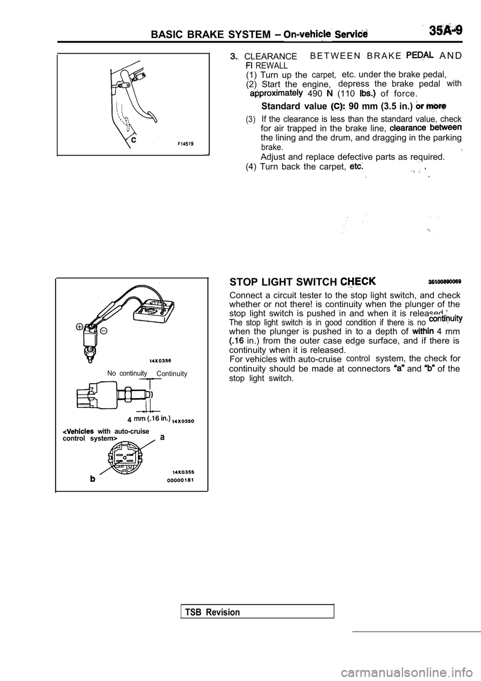
CLEARANCEB E T W E E N B R A K E A N D
REWALL
(1) Turn up thecarpet,etc. under the brake pedal,
(2) Start the engine, depress the brake pedal
with
490 (110 of force.
Standard value 90 mm (3.5 in.)
(3)If the clearance is less than the standard value, c
heck
for air trapped in the brake line,
the lining and the drum, and dragging in the parkin g
brake.
Adjust and replace defective parts as required.
(4) Turn back the carpet,
, .
No continuity Continuity
4
with auto-cruise
control systema
STOP LIGHT SWITCH
Connect a circuit tester to the stop light switch, and check
whether or not there! is continuity when the plunge r of the
stop light switch is pushed in and when it is relea sed.’
The stop light switch is in good condition if there is no
when the plunger is pushed in to a depth of 4 mm
in.) from the outer case edge surface, and if ther e is
continuity when it is released. For vehicles with auto-cruise
controlsystem, the check for
continuity should be made at connectors
and of the
stop light switch.
TSB Revision
Page 1722 of 2103
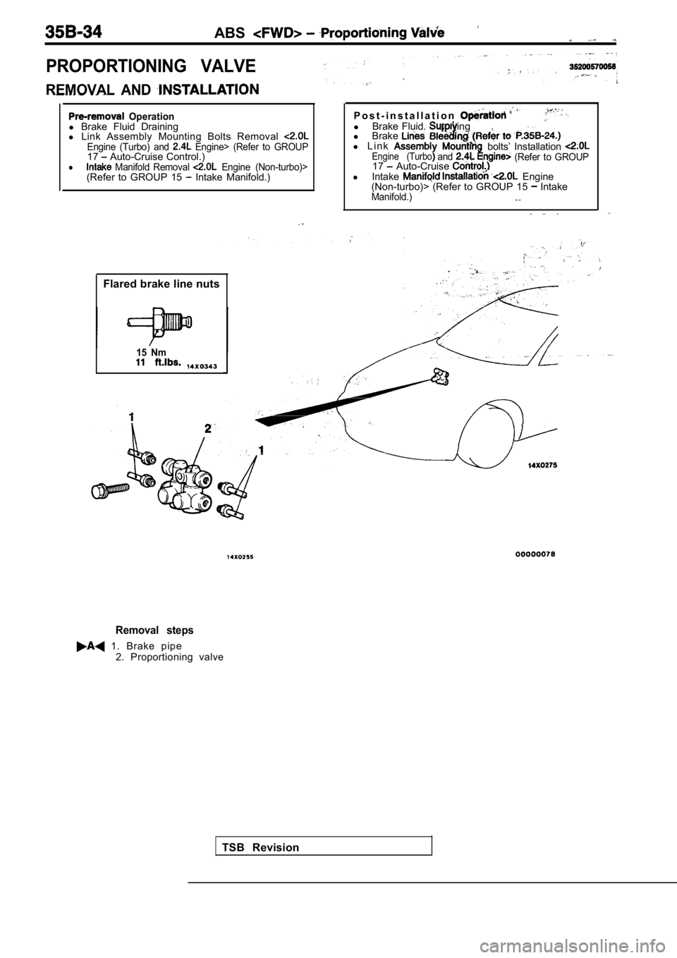
ABS
PROPORTIONING VALVE
REMOVAL AND
Operationl Brake Fluid Draining
l Link Assembly Mounting Bolts Removal
Engine (Turbo) and Engine> (Refer to GROUP17 Auto-Cruise Control.)l Manifold Removal Engine (Non-turbo)>(Refer to GROUP 15 Intake Manifold.)
Flared brake line nuts
15 Nm
P o s t - i n s t a l l a t i o nl Brake Fluid. ing
l Brake
l L i n kEngine (Turboandbolts’ Installation (Refer to GROUP17 Auto-Cruise l Intake Engine
(Non-turbo)> (Refer to GROUP 15 IntakeManifold.)
TSB Revision
Removal steps
1. Brake pipe
2. Proportioning valve
Page 2004 of 2103
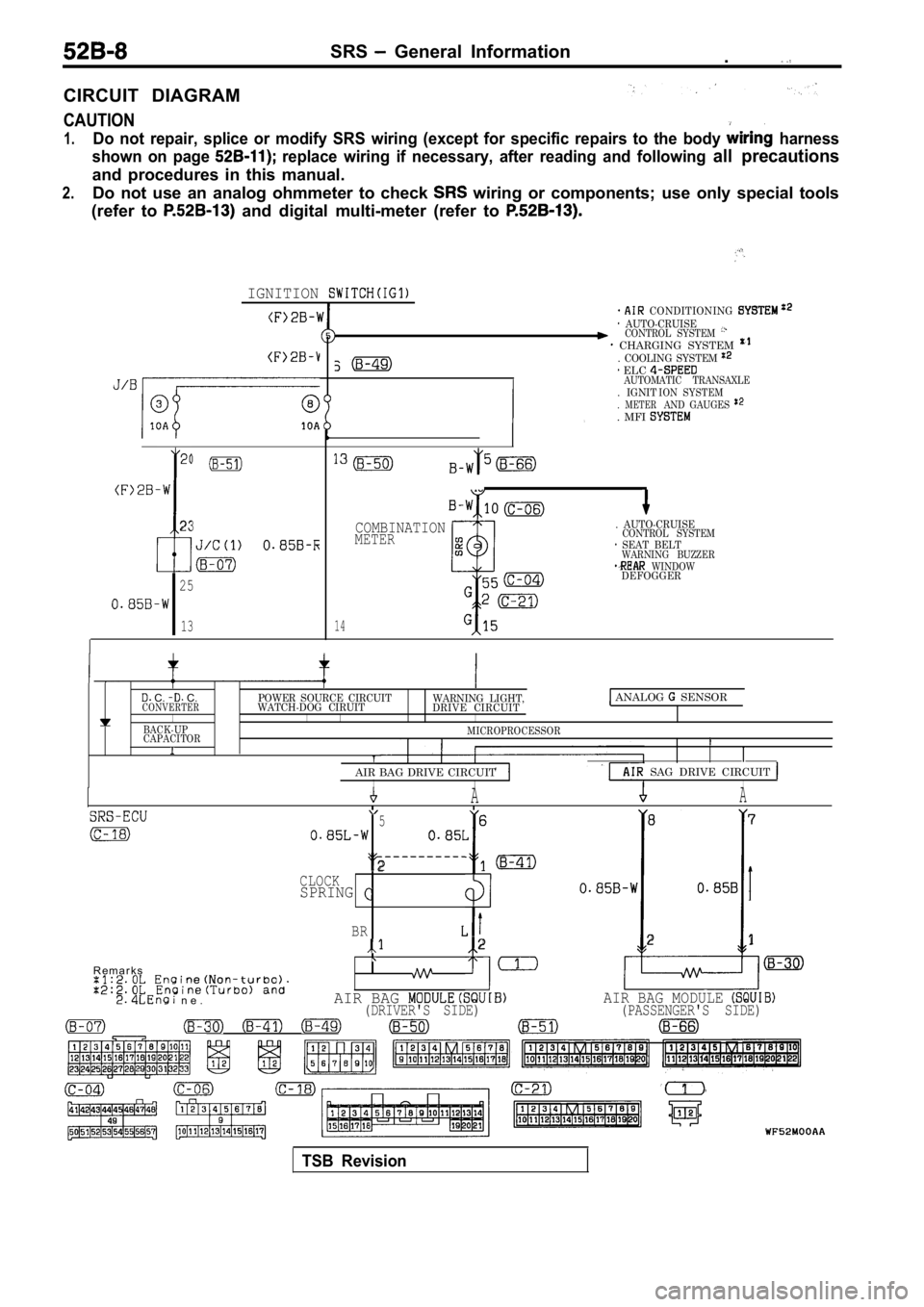
SRS General Information.
CIRCUIT DIAGRAM
CAUTION
1.Do not repair, splice or modify SRS wiring (except for specific repairs to the body harness
shown on page
replace wiring if necessary, after reading and fol lowing all precautions
and procedures in this manual.
2.Do not use an analog ohmmeter to check wiring or components; use only special tools
(refer to
and digital multi-meter (refer to
IGNITION
23
I
25
13
CONDITIONING AUTO-CRUISECONTROL SYSTEM CHARGING SYSTEM . COOLING SYSTEM
. IGNIT. METER. MFI
ELC AUTOMATIC TRANSAXLE ION SYSTEMAND GAUGES
14
COMBINATIONMETER
. AUTO-CRUISECONTROL SYSTEM SEAT BELTWARNING BUZZER WINDOWDEFOGGER
C. C.POWER SOURCE CIRCUITCONVERTERWATCH-DOG CIRUIT WARNING LIGHT,
DRIVE CIRCUIT ANALOG SENSOR
I IIIBACK-UP
CAPACITORMICROPROCESSORI
AIR BAG DRIVE CIRCUIT
SAG DRIVE CIRCUIT IIIAA
5 6 8
7
2CLOCKSPRINGI
BR2 21
R e m a r k s
n e .AIR BAG AIR BAG MODULE (DRIVER'S SIDE) (PASSENGER'S SIDE)
TSB Revision
Page 2035 of 2103
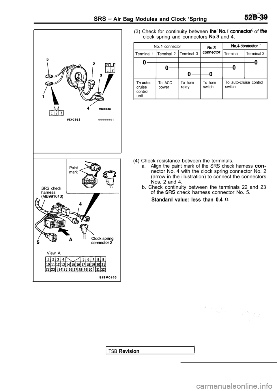
SRS Air Bag Modules and Clock ‘Spring
0 0 0 0 0 0 6 1
Paint
mark
SRS check
View A
(3) Check for continuity between of
clock spring and connectors and 4.
No. connector
Terminal1Terminal2Terminal3Terminal1Terminal2
0 0
0 0
0 0
Tocruise
control unitTo ACCpowerTo hornrelayTo hornTo auto-cruise control
switch switch
(4) Check resistance between the terminals.
a.Align the paint mark of the SRS check harness con-
nector No. 4 with the clock spring connector No. 2
(arrow in the illustration) to connect the connecto rs
Nos. 2 and 4.
b. Check continuity between the terminals 22 and 23 of the
check harness connector No. 5.
Standard value: less than 0.4
TSBRevision
Page 2093 of 2103

ALPHABETICAL
A
ABS OPERATIONCheck. . . . . . . . . . . . . . . . . . . . . . . . . . . . . . . . . . .
. . . . . . . . . . . . . . . . . . . . . . . . . . . . . . . . . . .
ABS-ECU. . . . . . . . . . . . . . . . . . . . . . . . . . . . . . . . . . . . . . . . .
. . . . . . . . . . . . . . . . . . . . . . . . . . . . . . . . . . . . . . . . .
ACCELERATOR CABLE. . . . . . . . . . . . . . . . . . . . . . . . . . . . . . . .Adjustment. . . . . . . . . . . . . . . . . . . . . . . . . . . . . . . . . . . . . . . . .
Check. . . . . . . . . . . . . . . . . . . . . . . . . . . . . . . . . . . . . . . . . . . . .ACCELERATOR PEDAL. . . . . . . . . . . . . . . . . . . . . . . . . . . . . . . .
ADAPTER, Transfer Case . . . . . . . . . . . . . . . . . .
AERO PARTS. . . . . . . . . . . . . . . . . . . . . . . . . . . . . . . . . . . . . . . .
AIR BAG CONTROL UNIT (SRS-ECU), SRS. . . . . . . . . . .AIR BAG MODULES. . . . . . . . . . . . . . . . . . . . . . . . . . . . . . . . .
Deployed Disposal Procedures. . . . . . . . . . . . . . . . . . . . .
Disposal Procedures. . . . . . . . . . . . . . . . . . . . . . . . . . . . .
Disposal. . . . . . . . . . . . . . . . . . . . . . . . . . . . .
AIR CLEANER ELEMENT, Maintenance. . . . . . . . . . . . . . . . . .AIR CONDITIONING SWITCH
ENGINE (NON-TURBO)>. . . . . . . . . . . . . . ENGINE (TURBO) AND .AIR COOLER, charge. . . . . . . . . . . . . . . . . . . . . . . . . . . . . . . . . . .
AIR FILTER. . . . . . . . . . . . . . . . . . . . . . . . . . . . . . . . . . . . . . . . . .
ALIGNMENT
Front Wheel, Check and Adjustment. . . . . . . . . . . . . . . . .
Wheel, Rear, Check and Adjustment. . . . . . . . . . . . . . . . . . .AMPLIFIER. . . . . . . . . . . . . . . . . . . . . . . . . . . . . . . . . . . . . . . . . .
GEAR AND TRANSFER DRIVE GEAR SET
. . . . . . . . . . . . . . . . . . . . . . . . . . . . . . . .
. . . . . . . . . . . . . . . . . . . . . . . . . . . . . . . . . . . . . . . .
ANTENNA.
ARM Compression, Lower
. . . . . . . . . . . . . . . . . . . . . . . . . . . . . . .Lateral, Lower. . . . . . . . . . . . . . . . . . . . . . . . . . . . . . . . . . .
Lower. . . . . . . . . . . . . . . . . . . . . . . . . . . . . . . . . . . . . . . . . . . . .
Toe Control. . . . . . . . . . . . . . . . . . . . . . . . . . . . . . . . . . . . . . . .
Trailing. . . . . . . . . . . . . . . . . . . . . . . . . . . . . . . . . . . . . . . . . . . .
Upper
Suspension>. . . . . . . . . . . . . . . . . . . . . . . . . . .ARMS, Rocker . . . . . . . . . . . . . . . . . . . . . . . . . . .11AUTO-CRUISE CONTROL. . . . . . . . . . . . . . . . . . . . . . . . . . . . .
AUTO-CRUISE CONTROL CABLE, Check andAdjustment. . . . . . . . . . . . . . . . . . . . . . . . . . . . . . . . . . . . . . . . . . .
AUTO-CRUISE CONTROL COMPONENT, Check. . . . . . . . .AUTO-CRUISE CONTROL SYSTEM, Operation Check. . . .AUTOMATIC TRANSAXLE FLUID, Maintenance. . . . . . . . . .AUTOMATIC TRANSAXLE CONTROL COMPONENTCheck
ENGINE (NON-TURBO)>.. . . . . . . . . . . .Layout ENGINE (NON-TURBO)>. . . . . . . . . . . .AUTOMATIC TRANSAXLE KEY INTERLOCK AND SHIFT LOCKMECHANISMS
ENGINE (NON-TURBO)>. . . . . . . . . . . . . . . . . . .
ENGINE (TURBO) AND ENGINE>.. . . . . . .AXLE
Rear, Total Backlash Check. . . . . . . . . . . . . . . . . . . . . . . . . .
AXLE OIL
Rear, Maintenance
. . . . . . . . . . . . . . . . . . . . . . . . . . . . . . . . .
BACK-UP LIGHT. . . . . . . . . . . . . . . . . . . . . . . . . . . . . . . . . . . . .BALL JOINT, Tie Rod End, Breakaway Torque Check. . . . .BALL JOINT SEALS, Maintenance. . . . . . . . . . . . . . . . . . . . . .
BARStabilizer Suspension>. . . . . . . . . . . . . . . . . . . . .
Suspension>. . . . . . . . . . . . . . . . . . . . . . . .
BASIC IDLE SPEED, Adjustment ENGINE (TURBO)
AND ENGINE>. . . . . . . . . . . . . . . . . . . . . . . . . . . . . . . .
BATTERY
Charging
. . . . . . . . . . . . . . . . . . . . . . . . . . . . . . . . . . . . . . . . . .
Check. . . . . . . . . . . . . . . . . . . . . . . . . . . . . . . . . . . . . . . . . . ..Testing Procedure. . . . . . . . . . . . . . . . . . . . . . . . . . . . .. . .
BELT
Compressor, Adjustment. . . . . . . . . . . . . . . . . . . . . . . . .
(For Generator), Maintenance. . . . . . . . . . . .. . . . . (For Power steering pump), Maintenance. . . . . . . . . (For Water pump), Maintenance. . . . . . . . .. .. . .Timing. . . . . . . . . . . . . . . . . . . .
. . . . . . . . . . . . . . . . . . . . . . . . . . .
Timing. . . . . . . . . . . . . . . . . . . . . . . . . . . . .
. . . . . . . . . . . . . . . . . . . . . ... . . . . . . . .
. . . .Timing, Maintenance. . . . . . . . . . . . . . . . . . . . . . . . . . . . . . . .
BLEEDING
ABS. . . . . . . . . . . . . . . . . . . . . . . . . . . . . . . . . . . . . . . . . . . .
Basic Brakes. . . . . . . . . . . . . . . . . . . . . . . . . . . . . . . . . . . .
Clutch. . . . . . . . . . . . . . . . . . . . . . . . . . . . . . . . . . .. . . . . . .. . . . . . . . . . . . . . . . . . . . . . . . . . . . . . . . . . . . . . . . . .
BLOWER. . . . . . . . . . . . . . . . . . . . . . . . . . . . . . . . . . . . . . . . . . . .
BOLTHub, Replacement . . . . . . . . . . . . . . . . . . .. . . . .
. . . . . . . . . . . . . . . . . . . . . .
. . . . . . . . . . . . . . . . . . . . . . 2 7 4 1
BOOSTER
Brake. . . . . . . . . . . . . . . . . . . . . . . . . . . . . . . . . . . .
. . . . . . . . . . . . . . . . . . . . . . . . . . . . .
Brake, Operating Test. . . . . . . . . . . . . . . . . . . . . . . . . . . . . O-IBOOTS, Shaft, Maintenance. . . . . . . . . . . . . . . . . . . . . . .
BRACKET. . . . . . . . . . . . . . . . . . . . . . . . . . . . . .
BRAKE
. . . . . . . . . . . . . . . . . . . . . . . . . . . . . . . . . . . . . .
Disc, Rear. . . . . . . . . . . . . . . . . . . . . . . . . . . . . . . . . . . . . . .
Low-reverse. . . . . . . . . .. . . . . . . .. . . . . . . . . . . . . . . . . . . . . . . . . . . .
BRAKE BOOSTER
. . . . . . . . . . . . . . . . . . . . . . . . . . . . . . . . . . . . . . . . . .
Test. . . . . . . . . . . . . . . . . . . . . . . . . . . . . . . . . . . .
BRAKE DISC
Front, Run-out Check. . . . . . . . . . . . . . . . . . . . . . . . . .. Run-out Correction. . . . . . . . . . . . . . . . . . . . . . . . . .
Front, Thickness Check. . . . . . . . . . . . . . . . . . . . . . . . . . .
Rear, Run-out Check.. . . . . . . . . . . . . . . . . . . . . . . . . . . . .
Rear, Run-out Correction. . . . . . . . . . . . . . . . . . . . . . . . . .
Rear, Thickness Check. . . . . . . . . . . . . . . . . . . . . . . . . . . .
BRAKE DRUM
Inside Diameter Check with Rear Drum . . . . . . . . . . . . . . . . . . . . . . . . . . . . . . . . . . . . . . . . . . . . . . . . .
BRAKE FLUID LEVEL SENSOR, Check. . . . . . . . . . . . . . . .
BRAKE HOSES, Maintenance. . . . . . . . . . . . . . . . . . . . . . . . . .
BRAKE LINING
Thickness. . . . . . . . . . . . . . . . . . . . . . . . . . . . . . . . . .
BRAKE PAD
Disc, Front, Check and Replacement
. . . . . . . . . . . . . . . .Disc, Rear, Check and Replacement. . . . . . . . . . . . . . . .
BRAKE PEDAL. . . . . . . . . . . . . . . . . . . . . . . . . . . . . . . . . . . . .
Check and Adjustment. . . . . . . . . . . . . . . . . . . .. . . . . . .BRAKE ROTOR, Disc, Front, Check. . . . . . . . . . . . . . . . .BREAKAWAY TORQUE, Rod End Ball Joint, . . .BUMPERFront. . . . . . . . . . . . . . . . . . . . . . . . . . . . . . . . . . . . . . . . . . . . . . .Rear. . . . . . . . . . . . . . . . . . . . . . . . . . . . . . . . . . . . . . . ......