Page 86 of 2103
E N G I N E Oil fan and Oil
OIL PAN AND OIL SCREEN
REMOVAL AND INSTALLATION
and Post-installation Operation
l Engine Oil Draining and Supplying
lOil Level Gauge Removal and InstallationlFront Exhaust Pipe Removal and Installation
GROUP 15 Exhaust Pipe and Muffler.)
(Refer to GROUP 15
Exhaust Pipe and Muffler.)
Nm
1
I
6.9 Nm5.1
29
I
6.66.5
Removal steps
1.Transfer assembly6.Gasket
2. Bell housing cover 7. Oil pan3.Drain plug8.Oil screen4.Gasket9.Gasket
5. Oil return pipe connection
TSB Revision
Page 177 of 2103

ENGINE Troubleshooting,
TROUBLESHOOTING
Symptom Probable causeRemedy
Compression too low Cylinder head gasket blown Replace gasket
Piston ring worn or damaged Replace rings
Piston or cylinder worn Repair or replace piston
cylinder
block
Valve seat worn or damaged Repair or replace valve seat ring
Oil pressure drop Engine oil level too low Check engi ne oil level
Oil pressure switch faulty Replace oil pressure switch
Oil filter clogged
Install new filter
Oil pump gears or cover
Replace gears and/or cover
Thin or diluted engine oil Change engine correct
Oil relief valve stuck (open) Repair relief valve
Excessive bearing clearance Replace bearings
pressure too highOil relief valve stuck (closed) Repair relief valve
valves Incorrect lash adjuster Bleed air or replace lash adjuster
Thin or diluted engine oil (low oil pressure) Change engine oil
Valve stem or valve guide worn or damaged Replace va lve
guide
rod noise/lnsuff oil supplyCheck engine oil level
nain bearing noise Low oil pressure Refer
pressure drop”
Thin or diluted engine oil Change engine oil
Excessive bearing clearance Replace bearings
belt noiseIncorrect belt tension
Adjust belt tension replace-timing
belt
engine rolling Loose engine roll stopper (Front, Re
ar)Retighten
vibration
Loose transaxle mount bracket Retighten
Loose engine mount bracket Retighten
Loose center member Retighten
Broken transaxle mount insulator
Replace
Broken engine mount insulatorReplace
Broken roll stopper insulatorReplace
TSB Revision
Page 183 of 2103

ENGINE On-vehicle.’
M A N I F O L D V A C U U M
1.Before inspection, set vehicles. in the condition:
Engine coolant
lLights, electric cooling and
lTransaxle: Neutral (P
2. Connect the scan tool to the data link connector.
,
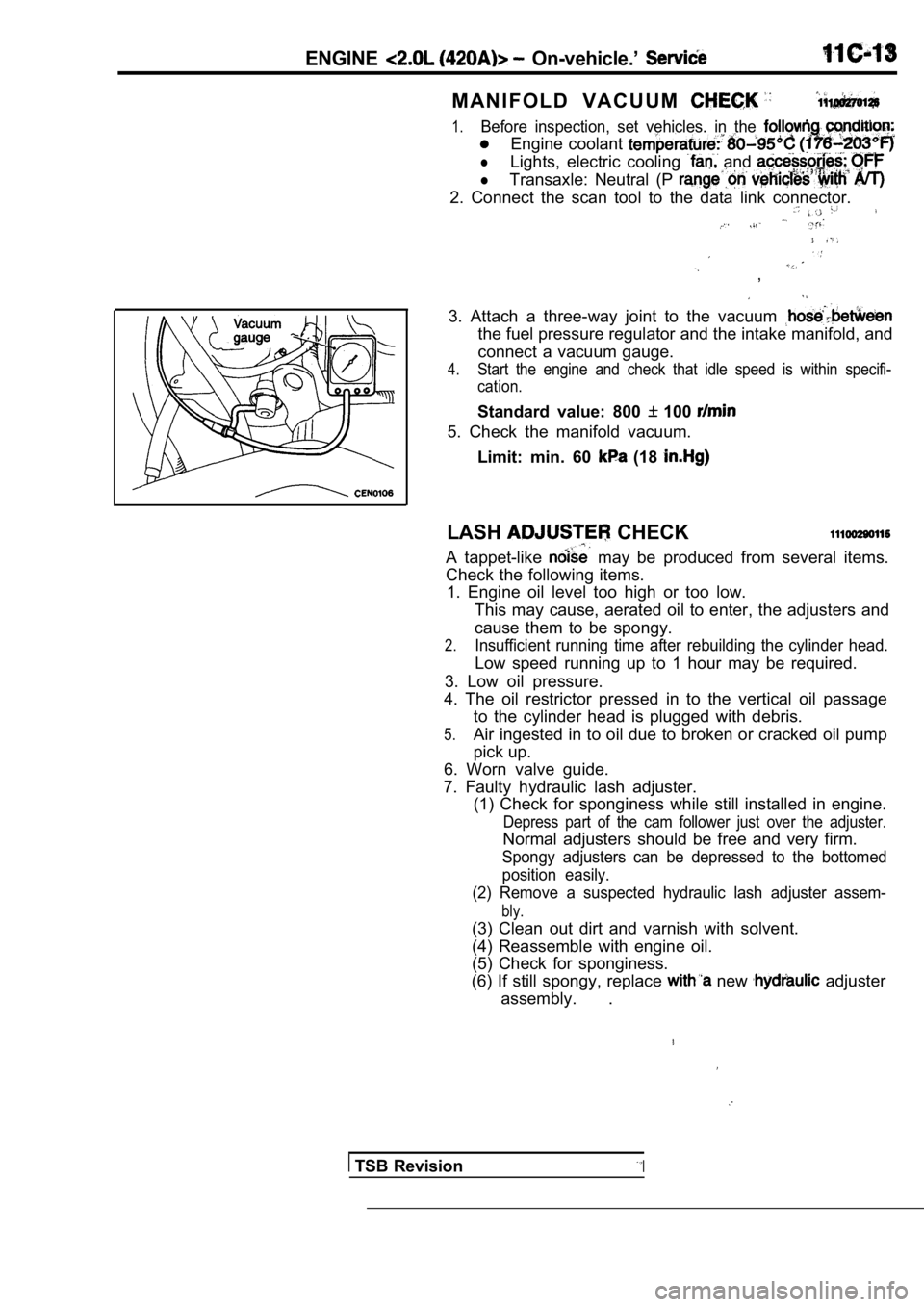
3. Attach a three-way joint to the vacuum
the fuel pressure regulator and the intake manifold, and
connect a vacuum gauge.
4.Start the engine and check that idle speed is withi n specifi-
cation.
Standard value: 800 100
5. Check the manifold vacuum.
Limit: min. 60
(18
LASH CHECK
A tappet-like may be produced from several items.
Check the following items. 1. Engine oil level too high or too low.
This may cause, aerated oil to enter, the adjusters and
cause them to be spongy.
2.Insufficient running time after rebuilding the cyli nder head.
Low speed running up to 1 hour may be required.
3. Low oil pressure.
4. The oil restrictor pressed in to the vertical oi l passage
to the cylinder head is plugged with debris.
5.Air ingested in to oil due to broken or cracked oil pump
pick up.
6. Worn valve guide.
7. Faulty hydraulic lash adjuster. (1) Check for sponginess while still installed in e ngine.
Depress part of the cam follower just over the adju ster.
Normal adjusters should be free and very firm.
Spongy adjusters can be depressed to the bottomed
position easily.
(2) Remove a suspected hydraulic lash adjuster asse m-
bly.
(3) Clean out dirt and varnish with solvent.
(4) Reassemble with engine oil.
(5) Check for sponginess.
(6) If still spongy, replace
new adjuster
assembly. .
TSB RevisionI
Page 194 of 2103
ENGINE Oil Pan and Oil Screen
OIL PAN AND OIL SCREEN
REMOVAL AND INSTALLATION
and Post-installation OperationlEngine Oil Draining and SupplyingOil Level Gauge Removal and lFront Exhaust Pipe Removal and Installation
(Refer to GROUP 15 Exhaust Pipe and Muffler.)
Specified sealant: 5699 or
equivalent
TSB Revision
Removal steps
1.Drain plug2.Gasket3.Front plate4.Oil pan
5. Oil pan gasket
6.Oil screen7. O-ring
108 Nm
8.9
Page 228 of 2103

11 ENGINE OVERHAUL Cooling System
(1) Install switch.
(2) Install engine coolant
lighten sensor
to 7 Nm (5
torque.
Overflownipple
Pressure cap
Impeller
TSB Revision
O-ring
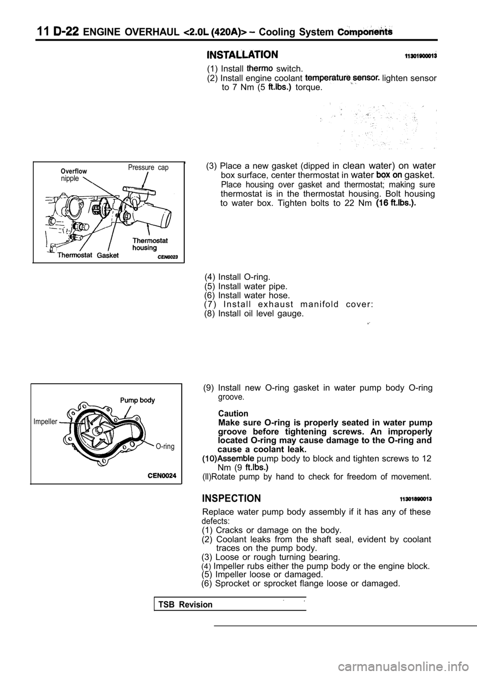
(3) Place a new gasket (dipped in clean water) on water
box surface, center thermostat in water
gasket.
Place housing over gasket and thermostat; making su re
thermostat is in the thermostat housing. Bolt housing
to water box. Tighten bolts to 22 Nm
(4) Install O-ring.
(5) Install water pipe.
(6) Install water hose.
( 7 ) I n s t a l l e x h a u s t m a n i f o l d c o v e r :
(8) Install oil level gauge.
(9) Install new O-ring gasket in water pump body O- ring
groove.
Caution
Make sure O-ring is properly seated in water pump
groove before tightening screws. An improperly
located O-ring may cause damage to the O-ring and
cause a coolant leak.
pump body to block and tighten screws to 12
Nm (9
(ll)Rotate pump by hand to check for freedom of mov ement.
INSPECTION
Replace water pump body assembly if it has any of these
defects:
(1) Cracks or damage on the body.
(2) Coolant leaks from the shaft seal, evident by c oolant
traces on the pump body.
(3) Loose or rough turning bearing.
(4) Impeller rubs either the pump body or the engine bl ock.
(5) Impeller loose or damaged.
(6) Sprocket or sprocket flange loose or damaged.
Page 233 of 2103
ENGINE OVERHAUL Exhaust
EXHAUST MANIFOLD
REMOVAL
(1) Remove oil level gauge.
(2) Remove exhaust manifold. heat shield,
(3) Remove 8 exhaust manifold retaining and
move exhaust manifold.
(1) Install new manifold gasket. DO NOT APPLY-SEALER.
(2) Set exhaust manifold in
Tighten nuts
and bolt, starting at center and
in
both directions to 23
procedure until all fasteners are specified
(3) Install exhaust manifold heat shield, ,
(4) Install oil level gauge.
CLEANING AND INSPECTION
(1) Discard gasket and clean all gasket surfaces of manifolds
and cylinder head.
(2) Test manifold gasket surfaces for flatness with straight
edge. Surface must be flat within 0.15 mm per 300 m m
in. per foot) of manifold length.
(3) Inspect manifolds for cracks or distortion. Rep lace man-
ifold if necessary.
TSB Revision
Page 261 of 2103
OVERHAUL
CRANKSHAFT
REMOVAL
Procedures after removing crankshaft sprocket, oil pan, pis-
tons and connecting rods.
(1) Using Tool remove front crankshaft oil seal.
Be careful not to damage the seal surface of cover.
(2) out rear seal with screwdriver. Becareful not to nick
or damage crankshaft flange seal surface or retaine r bore.
(3) Remove main bearing cap
(4) Remove bearing lower.
(5) Remove crankshaft.
(6) Remove bearing upper.
(7) Remove knock sensor.
(8) Remove oil pressure switch.
(9) Remove oil level gauge (dipstick).
Revision
Page 262 of 2103
ENGINE Crankshaft
Oil holes
I N S T A L L A T I O N
(1) Install oil level gauge (dipstick).
(2) Install oil pressure switch.
,
,
(3) Install knock sensor. Tighten knock sensor to 10 Nm
(7 torque. Over or under tightening effects knock
sensor performance, possibly causing improper spark con-
t r o l .
(4) Select proper thickness main bearing shells by referring
to CRANKSHAFT BEARING CLEARANCE.
NOTE
Upper and lower No. 3 bearing halves are flanged to
carry the crankshaft thrust loads and are NOT inter change-
able with any other bearing halves in the engine. Bearing
shells are available in standard and the following under-
sized:
0.016 mm, 0.032 mm, 0.250 mm.
Never install an undersize bearing that will reduce clear-
ance below specifications.
(5) Install the main bearing shells with the lubric ation groove
in the cylinder block.
TSB Revision