1990 MITSUBISHI SPYDER oil level
[x] Cancel search: oil levelPage 1495 of 2103
SHAFT Propeller
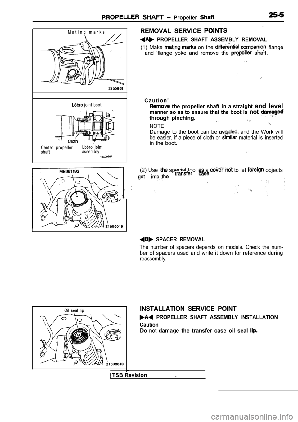
M a t i n g m a r k s
joint boot
Center propeller
shaft Lbbro’ joint
assembly
REMOVAL SERVICE
PROPELLER SHAFT ASSEMBLY REMOVAL
(1) Make on the flange
and ‘flange yoke and remove the
shaft.
. .
C a u t i o n ’
the propeller shaft in a straight and level
manner so as to ensure that the boot is not
through pinching. ,
NOTE
Damage to the boot can be and the Work will
be easier, if a piece of cloth or material is inserted
in the boot.
(2) Use special tool a to let objects
SPACER REMOVAL
The number of spacers depends on models. Check the num-
ber of spacers used and write it down for reference during
reassembly.
Oil seal lipINSTALLATION SERVICE POINT
PROPELLER SHAFT ASSEMBLY INSTALLATION
Caution
Do not damage the transfer case oil seal
TSB Revision. .
Page 1535 of 2103
R E A R A X L E
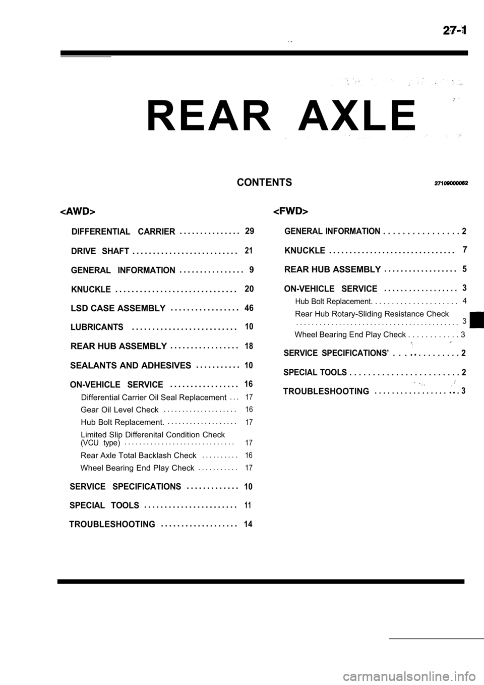
CONTENTS
DIFFERENTIAL CARRIER. . . . . . . . . . . . . . .29
DRIVE SHAFT
. . . . . . . . . . . . . . . . . . . . . . . . . .21
GENERAL INFORMATION. . . . . . . . . . . . . . . .9
KNUCKLE
. . . . . . . . . . . . . . . . . . . . . . . . . . . . . .20
LSD CASE ASSEMBLY . . . . . . . . . . . . . . . . .46
LUBRICANTS. . . . . . . . . . . . . . . . . . . . . . . . . .10
REAR HUB ASSEMBLY. . . . . . . . . . . . . . . . .18
SEALANTS AND ADHESIVES . . . . . . . . . . .10
ON-VEHICLE SERVICE. . . . . . . . . . . . . . . . .16
Differential Carrier Oil Seal Replacement
. . .17
Gear Oil Level Check. . . . . . . . . . . . . . . . . . . .16
Hub Bolt Replacement. . . . . . . . . . . . . . . . . . . .17
Limited Slip Differenital Condition Check(VCU type). . . . . . . . . . . . . . . . . . . . . . . . . . . . . .17
Rear Axle Total Backlash Check
. . . . . . . . . .16
Wheel Bearing End Play Check. . . . . . . . . . .17
SERVICE SPECIFICATIONS. . . . . . . . . . . . .10
SPECIAL TOOLS. . . . . . . . . . . . . . . . . . . . . . .11
TROUBLESHOOTING. . . . . . . . . . . . . . . . . . .14
GENERAL INFORMATION . . . . . . . . . . . . . . . .
2
KNUCKLE. . . . . . . . . . . . . . . . . . . . . . . . . . . . . . .7
REAR HUB ASSEMBLY . . . . . . . . . . . . . . . . . .
5
ON-VEHICLE SERVICE. . . . . . . . . . . . . . . . . .3
Hub Bolt Replacement. . . . . . . . . . . . . . . .
. . . . .4
Rear Hub Rotary-Sliding Resistance Check
. . . . . . . . . . . . . . . . . . . . . . . . . .
. . . . . . . . . . . . . . . .3
Wheel Bearing End Play Check . . . . . . . . . . .
. 3
SERVICE SPECIFICATIONS’ . . . . . . . . . . . . 2
SPECIAL TOOLS . . . . . . . . . . . . . . . . . . . . . . . . 2
TROUBLESHOOTING. . . . . . . . . . . . . . . . . . 3
Page 1550 of 2103
6REAR AXLE Service
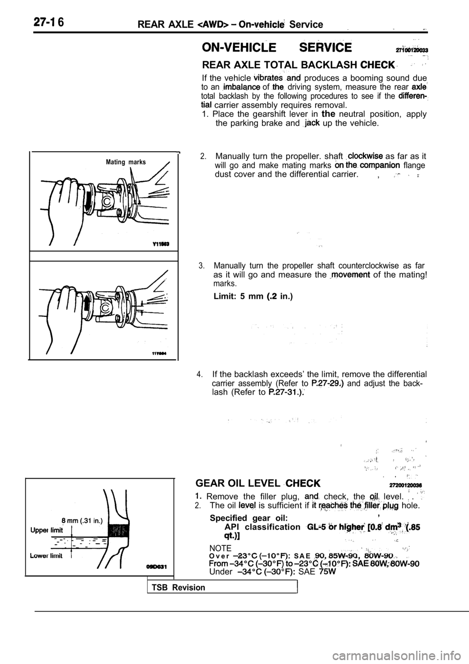
REAR AXLE TOTAL BACKLASH
If the vehicle produces a booming sound due
to an of driving system, measure the rear
total backlash by the following procedures to see if the
carrier assembly requires removal.
1. Place the gearshift lever in theneutral position, apply
the parking brake and
up the vehicle.
Mating marks2.Manually turn the propeller. shaft as far as it
will go and make mating marks flange
dust cover and the differential carrier. ,
3.Manually turn the propeller shaft counterclockwise as far
as it will go and measure the of the mating!
marks.
Limit: 5 mm in.)
4.If the backlash exceeds’ the limit, remove the differential
carrier assembly (Refer to and adjust the back-
lash (Refer to
TSB Revision
GEAR OIL LEVEL
Remove the filler plug, check, the level. .
2.The oil is sufficient if hole.
Specified gear oil: ,
API classification
NOTEO v e r S A E
Under SAE
Page 1604 of 2103
FRONT __
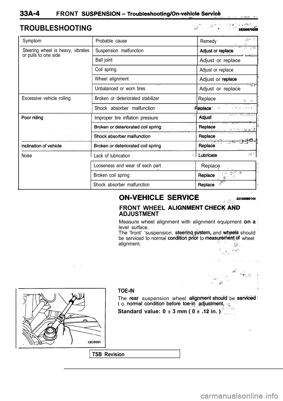
TROUBLESHOOTING
, .
SymptomProbable cause
Remedy
Steering wheel is heavy, vibratesSuspension malfunction
or pulls to one side, ,
Ball jointAdjust or replace
Coil spring
Wheel alignment
Unbalanced or worn tires Adjust or replace
Adjust or
Adjust or replace
Excessive vehicle rollingBroken or deteriorated stabilizer
Shock absorber malfunction
Replace
Improper tire inflation pressure
NoiseLack of lubrication
Looseness and wear of each part
.
Broken coil spring
Shock absorber malfunction
Replace
FRONT WHEEL
ADJUSTMENT
Measure wheel alignment with alignment equipment on a
level surface.
The ‘front’ ‘suspension, and should
be serviced to normal to wheel
alignment.
TOE-IN
The suspension wheel be
t o
Standard value: 0 3 mm 0 in.
TSB Revision
Page 1775 of 2103
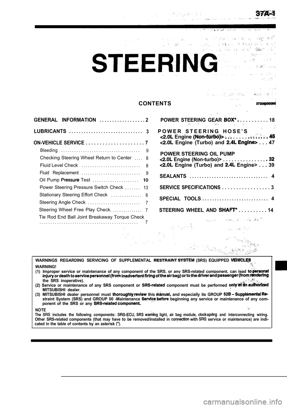
CONTENTS
GENERAL INFORMATION. . . . . . . . . . . . . . . . . . 2POWER STEERING GEAR . . . . . . . . . . 18
LUBRICANTS. . . . . . . . . . . . . . . . . . . . . . . . . . . . . .
3P O W E R S T E E R I N G H O S E ’ S
Engine . . . . .
ON-VEHICLE SERVICE . . . . . . . . . . . . . . . . . . . . . 7 Engine (Turbo) and . . . 47
Bleeding. . . . . . . . . . . . . . . . . . . . . . . . . . . . . . . . . . . .9
Checking Steering Wheel Return to Center
. . . .8
Fluid Level Check. . . . . . . . . . . . . . . . . . . . . . . . . . .8
Fluid Replacement. . . . . . . . . . . . . . . . . . . . . . . . . . .9
Oil Pump Test
. . . . . . . . . . . . . . . . . . . . .
Power Steering Pressure Switch Check
. . . . . . .13
Stationary Steering Effort Check. . . . . . . . . . . . . .8
Steering Angle Check. . . . . . . . . . . . . . . . . . . . . . . .7
Steering Wheel Free Play Check. . . . . . . . . . . . . . .7
Tie Rod End Ball Joint Breakaway Torque Check
. . . . . . . . . . . . . . . . . . . . . . . . . . . . . . . . . . . . . . . . . . . . .
7
POWER STEERING OIL PUMP
Engine (Non-turbo)> . . . . . . . . . . . . . . .
Engine (Turbo) and Engine> . . . 39
SEALANTS. . . . . . . . . . . . . . . . . . . . . . . . . . . . . . . .4
SERVICE SPECIFICATIONS . . . . . . . . . . . . . . . . . 3
SPECIAL TOOLS. . . . . . . . . . . . . . . . . . . . . . . . . . .4
STEERING WHEEL AND
. . . . . . . . . . 14
WARNINGS REGARDING SERVICING OF SUPPLEMENTAL (SRS) EQUIPPED
WARNING!(1)Improper service or maintenance of any component of the SRS, or any SRS-related component, can lead
the SRS inoperative).(2) Service or maintenance of any SRS component or component must be performed MITSUBISHI dealer.(3) MITSUBISHI dealer personnel must this and especially its GROUP straint System (SRS) and GROUP 00 -Maintenance beginning any service or maintenance of any com-
ponent of the SRS or any
NOTEThe includes the following components: SRS light, air bag module, and interconnecting wiring.Other SRS-related components (that may have to be r emoved/installed in with service or maintenance) are indi-
cated in the table of contents by an asterisk
Page 1782 of 2103
STEERING On-vehicle Service
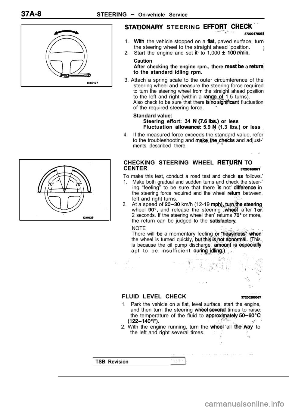
S T E E R I N G
1. the vehicle stopped on a paved surface, turn
the steering wheel to the straight ahead ‘position.
2.Start the engine and set to 1,000
Caution
After checking the engine rpm., there
a
to the standard idling rpm.
3. Attach a spring scale to the outer circumference of the
steering wheel and measure the steering force requi red
to turn the steering wheel from the straight ahead position
to the left and right (within a 1.5 turns).
Also check to be sure that there fluctuation
of the required steering force.
Standard value:
Steering effort: 34
or less
Fluctuation
5.9 (1.3 Ibs.) or less
4.If the measured force exceeds the standard value, r efer
to the troubleshooting and
and adjust-’
ments described there.
CHECKING STEERING WHEEL TO
CENTER
To make this test, conduct a road test and check follows.’
1.Make both gradual and sudden turns and check the st eer-”
ing “feeling” to be sure that there not’ in
the steering force required and the wheel between,
left and right turns.
2.At a speed of km/h (12-19
wheel and release the steering after
2 seconds. If the steering wheel then’ returns or more,
the return can be judged to the
NOTE ,
There will a momentary feeling
the wheel is turned quickly, (This.
is because the oil pump discharge,
a p t t o b e i n s u f f i c i e n t
FLUID LEVEL CHECK
1.Park the vehicle on a flat, level surface, start th e engine,
and then turn the steering times to raise:
the temperature of the fluid to
2. With the engine running, turn the ‘all to
the left and right several times.
TSB Revision
Page 1783 of 2103
STEERING On-vehicle
Fluid fluctuation
While enginerunningWhile engine
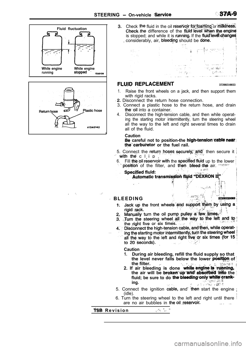
Check fluid in the oil or
difference of the
is stopped; and while it is If the
considerably, air, should be
37200210033
1.Raise the front wheels on a jack, and then support them
with rigid racks.
Disconnect the return hose connection.
3. Connect a plastic hose to the return hose, and d rain
into a container.
4.Disconnect the high-tension cable, and then while operat-
ing the starting motor intermittently, turn the steering wheel
all the way to the left and right several times to drain
all of the fluid.
Caution
careful not to position-the
or the fuel rail.
5. Connect the then secure it
c l i p .
6.Fill the up to the lower
of the filter, and air.
B L E E D I N G
. .
Caution
1.During air bleeding, refill the fluid supply so tha t
the level never falls below the lower
of
the filter.
2. If air bleeding is done
the air will be the
fluid; be sure to do
ing.
5. Connect the ignition and’ start the engine
(idle).
6. Turn the steering wheel to the left and right un til there
are no air bubbles in
R e v i s i o n.
Page 1784 of 2103
Fluid fluctuation
While engineWhile enginerunning stopped
PressureShut-off valv close)
NOTE
l l: Engine(Turbo) and Engine> 848 (Non-turbo)>
l 2: Engine (Turbo) and
Engine (Non-turbo)>
7. Confirm that fluid is the level
up the specified the
8. Confirm that there is change
when the steering wheel is turned,
9. Check whether or not in the fluid is
within 5 mm
in.) when the and
when it is running.
Caution
1. Ifthe change of
or more, the has bled,
from the system, and be bled ,
the fluid level rises suddenly after the engine,
stopped, the air has not completely
3.If air bleeding is not there will be
noises from the flow-control;
valve, ‘and
condition the life of,
the pump, etc.. ,
. . .
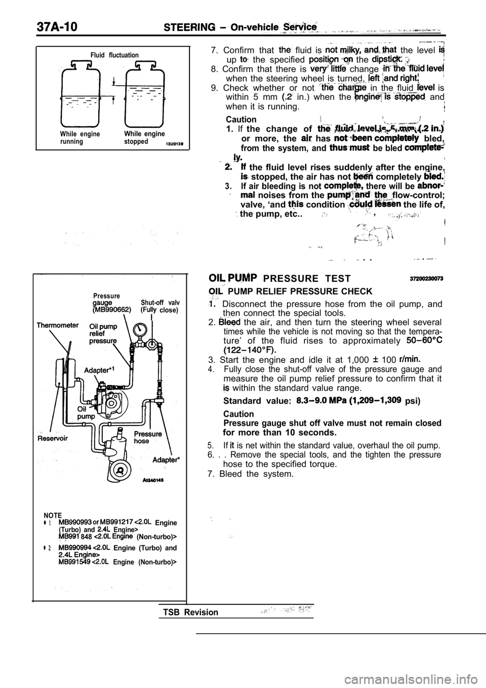
PRESSURE TEST
PUMP RELIEF PRESSURE CHECK
Disconnect the pressure hose from the oil pump, an d
then connect the special tools.
2.
the air, and then turn the steering wheel several
times while the vehicle is not moving so that the t empera-
ture’ of the fluid rises to approximately
3. Start the engine and idle it at 1,000 100
4.Fully close the shut-off valve of the pressure gaug e and
measure the oil pump relief pressure to confirm tha t it
within the standard value range.
Standard value:
psi)
Caution Pressure gauge shut off valve must not remain close d
for more than 10 seconds.
5.If is net within the standard value, overhaul the oil pump.
6. . . Remove the special tools, and the tighten th e pressure
hose to the specified torque.
7. Bleed the system.
TSB Revision