1989 MITSUBISHI GALANT oil level
[x] Cancel search: oil levelPage 818 of 1273
25-4PROPELLER SHAFT - Propeller Shaft
PROPELLER SHAFT
REMOVAL AND INSTALLATION
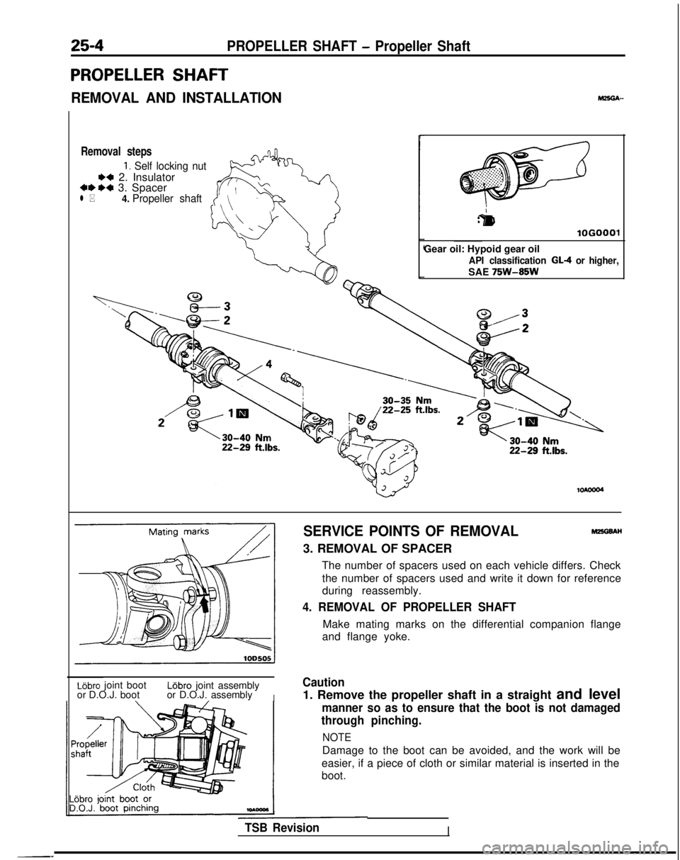
Removal steps
1. Self locking nut
** 2. Insulator***a 3. Spacerl *4.
Propeller shaft
r
:&I
lOGO
Gear oil: Hypoid gear oil
API classification GL-4 or higher,
SAE 75W-85W
SERVICE POINTS OF REMOVALMEGBAH
3. REMOVAL OF SPACER
The number of spacers used on each vehicle differs. Checkthe number of spacers used and write it down for reference
during reassembly.
4. REMOVAL OF PROPELLER SHAFT
Make mating marks on the differential companion flange
and flange yoke.
Lijbro joint bootL6bro joint assembly
or D.O.J. boot or D.O.J. assembly
I
Caution
1. Remove the propeller shaft in a straight and level
manner so as to ensure that the boot is not damaged
through pinching.
NOTE
Damage to the boot can be avoided, and the work will be
easier, if a piece of cloth or similar material is inserted in the
boot.
TSB RevisionI
Page 861 of 1273
27-1
mnAA-
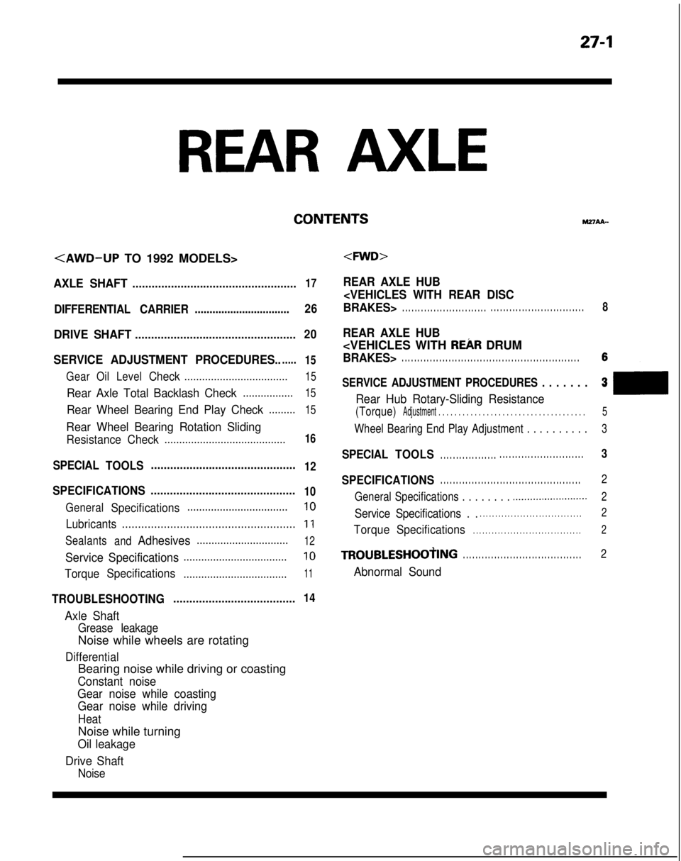
AXLE SHAFT...................................................17
DIFFERENTIAL CARRIER................................26
DRIVE SHAFT.................................................. 20
SERVICE ADJUSTMENT PROCEDURES.......
15
Gear OilLevelCheck ...................................15
Rear Axle Total Backlash Check.................15
Rear Wheel Bearing End Play Check.........15
Rear Wheel Bearing Rotation Sliding
Resistance Check .........................................16
REAR AXLE HUB
SPECIAL
TOOLS.............................................12
SPECIFICATIONS
.............................................10
GeneralSpecifications..................................10
Lubricants
......................................................11
Sealants
andAdhesives...............................12
Service Specifications...................................10
TorqueSpecifications
...................................11
TROUBLESHOOTING ......................................14
Axle Shaft
Grease leakage
Noise while wheels are rotating
Differential
Bearing noise while driving or coasting
Constant noise
Gear noise while coasting Gear noise while driving
Heat
Noise while turning
Oil leakage
Drive Shaft
Noise
. . . . . . . . . . . . . . . . . . . . . . . . . . . . . . . . . . . . . . . . . . . . . . . . . . . . . . . . .8
REAR AXLE HUB
. . . . . . . . . . . . . . . . . . . . .
SERVICE ADJUSTMENT PROCEDURES . . . . . . .h3
Rear Hub Rotary-Sliding Resistance
(Torque)Adjustment . . . . . . . . . . . . . . . . . . . . . . . . . . . . . . .\
. . . . . .5
Wheel Bearing End Play Adjustment . . . . . . . . . .3
SPECIAL
TOOLS. . . . . . . . . . . . . . . . . . . . . . . . . . . . . . . . . . . . . . . . . . . . .3
SPECIFICATIONS. . . . . . . . . . . . . . . . . . . . . . . . . . . . . . . . . . . . \
. . . . . . . . .2
General Specifications . . . . . . . .
.._.......................2
Service Specifications . .. . . . . . . . . . . . . . . . . . . . . . . . . . . . . . . . .2
Torque Specifications. . . . . . . . . . . . . . . . . . . . . . . . . . . . . . . . . . .2
TROUBLESHOOtING. . . . . . . . . . . . . . . . . . . . . . . . . . . . . . . . . . . . \
. .2
Abnormal Sound
Page 874 of 1273
27-14REAR AXLE
rROUBLESHOOTlNG
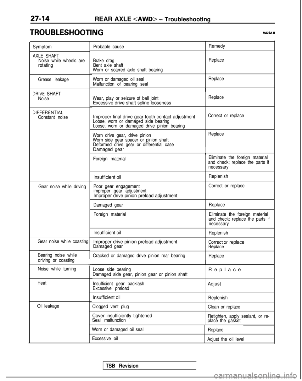
Symptom
AXLE SHAFTNoise while wheels are
rotating
Grease leakage
IRIVE SHAFT
Noise
IIFFERENTIAL Constant noise
Gear noise while driving
Gear noise while coasting Bearing noise while driving or coasting
Noise while turning
Heat
Oil leakage
c
Probable cause
Brake dragBent axle shaft
Worn or scarred axle shaft bearing
Worn or damaged oil seal
Malfunction of bearing seal Remedy
Replace
Replace
Wear, play or seizure of ball joint
Excessive drive shaft spline looseness
Replace
Improper final drive gear tooth contact adjustmentLoose, worn or damaged side bearing Loose, worn or damaged drive pinion bearing Correct or replace
Worn drive gear, drive pinion Worn side gear spacer or pinion shaft Deformed drive gear or differential case
Damaged gear -
Replace
Foreign material Eliminate the foreign material
and check; replace the parts if necessary
Insufficient oil
Poor gear engagementimproper gear adjustment
Improper drive pinion preload adjustment
Replenish
Correct or replace
Damaged gear Foreign material Replace
Eliminate the foreign material
and check; replace the parts if necessary
Insufficient oil
Improper drive pinion preload adjustment
Damaged gear
Cracked or damaged drive pinion rear bearing ReplenishCZ23rar2cr replace
Replace
Loose side bearing
Damaged side gear, pinion gear or pinion shaft
Insufficient gear backlash
Excessive preload
Insufficient oil
Clogged vent plug
Cover insufficiently tightenedSeal malfunction
Replac
e
Adjust
Replenish
Clean or replace
Retighten, apply sealant, or re-
place the gasket
Worn or damaged oil seal
Excessive oil Replace
Adjust the oil level
TSB Revision
Page 875 of 1273
REAR AXLE
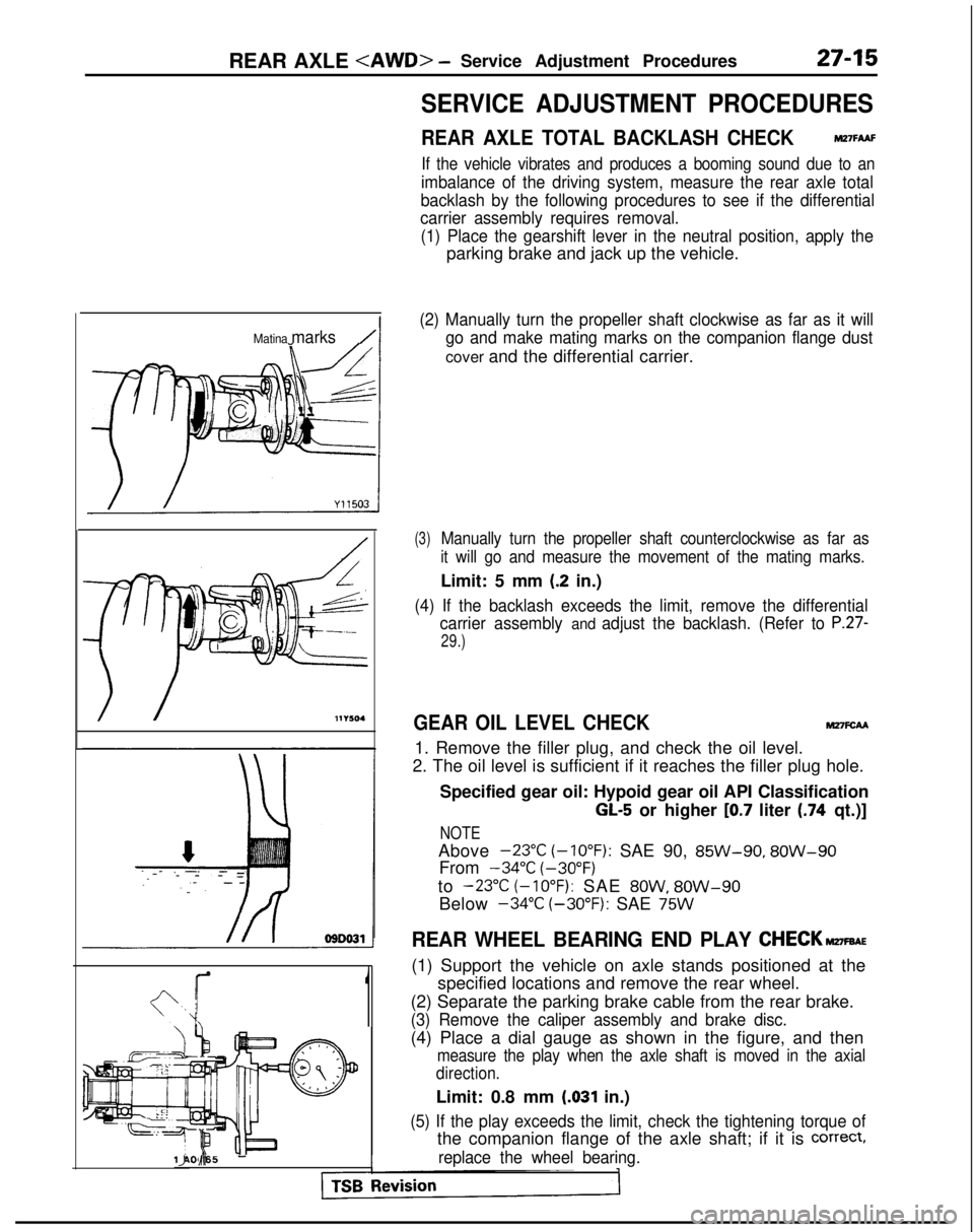
Matina marks/I
1
SERVICE ADJUSTMENT PROCEDURES
REAR AXLE TOTAL BACKLASH CHECKMZ’IFAAF
If the vehicle vibrates and produces a booming sound due to an
imbalance of the driving system, measure the rear axle total
backlash by the following procedures to see if the differential
carrier assembly requires removal.
(1) Place the gearshift lever in the neutral position, apply the
parking brake and jack up the vehicle.
(2) Manually turn the propeller shaft clockwise as far as it will go and make mating marks on the companion flange dust
cover and the differential carrier.
(3)Manually turn the propeller shaft counterclockwise as far as
it will go and measure the movement of the mating marks.
Limit: 5 mm (.2 in.)
(4) If the backlash exceeds the limit, remove the differential carrier assembly
and adjust the backlash. (Refer to P.27-
29.)
GEAR OIL LEVEL CHECKM27FcAA
1. Remove the filler plug, and check the oil level.
2. The oil level is sufficient if it reaches the filler plug hole.
Specified gear oil: Hypoid gear oil API Classification
GL-5 or higher [0.7 liter (.74 qt.)]
NOTE
Above -23°C
(-10°F):
SAE 90, 85W-90,
8OW-90
From -34°C
(-30°F)
to
-23°C (-10°F): SAE 8OW, 8OW-90
Below -34°C
(-30°F):
SAE
75W
REAR WHEEL BEARING END PLAY CHECK~FBAE
(1) Support the vehicle on axle stands positioned at the
specified locations and remove the rear wheel.
(2) Separate the parking brake cable from the rear brake.
(3) Remove the caliper assembly and brake disc.
(4) Place a dial gauge as shown in the figure, and then
measure the play when the axle shaft is moved in the axial
direction.
Limit: 0.8 mm (.031 in.)
(5) If the play exceeds the limit, check the tightening torque of
the companion flange of the axle shaft; if it is correct,
replace the wheel bearing.llA0065 IJ d-
Page 994 of 1273
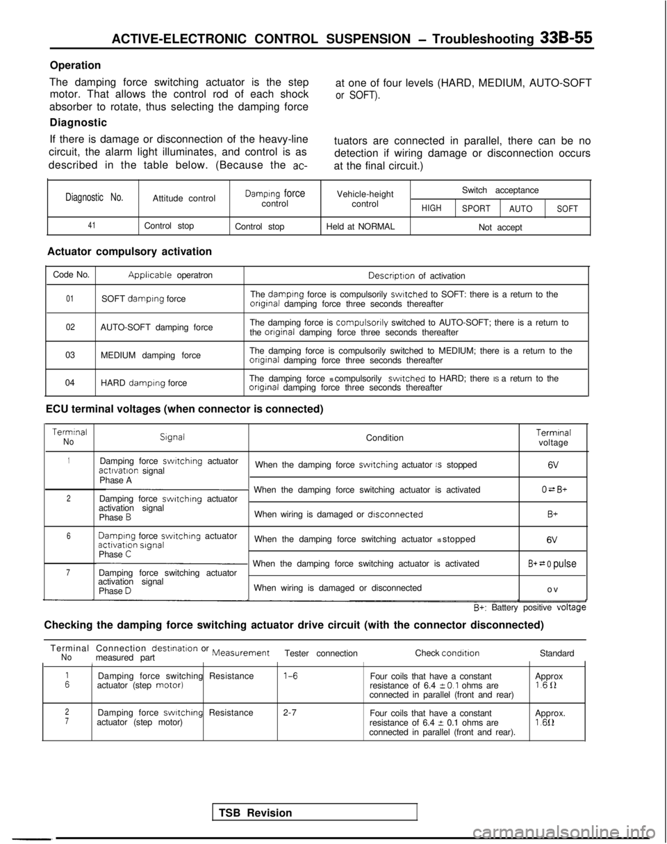
ACTIVE-ELECTRONIC CONTROL SUSPENSION - Troubleshooting 33B-55
Operation
The damping force switching actuator is the step motor. That allows the control rod of each shock at one of four levels (HARD, MEDIUM, AUTO-SOFT
or SOFT).
absorber to rotate, thus selecting the damping force
Diagnostic
If there is damage or disconnection of the heavy-line
circuit, the alarm light illuminates, and control is as
described in the table below. (Because the
ac-
tuators are connected in parallel, there can be no detection if wiring damage or disconnection occurs
at the final circuit.)
Diagnostic No.Attitude control
41Control stop
Actuator compulsory activation
Damplng forcecontrol
Control stop Vehicle-height
control
Held at NORMALHIGH
Switch acceptance
SPORT AUTO
Not accept
SOFT
Code No.Applrcable operatron Descriptron
of activation
01SOFT damplng force The damplng force is compulsorily swltched to SOFT: there is a return to theonginal damping force three seconds thereafter
02AUTO-SOFT damping force The damping force is compulsorily switched to AUTO-SOFT; there is a return to
the onginal damping force three seconds thereafter
03 MEDIUM damping force The damping force is compulsorily switched to MEDIUM; there is a return \
to the
onginal damping force three seconds thereafter
04 HARD
damplng force The damping force IS compulsorily switched to HARD; there IS a return to theonginal damping force three seconds thereafter
ECU terminal voltages (when connector is connected) Terminal
No
Slgnal
Condition Terminal
voltage
1Damping force swrtchlng
actuatoractlvatlon signal When the damping force switching actuator IS stopped6V
Phase AO=B+2p When the damping force switching actuator is activated
Damping force switching actuator
activation signal
Phase
BWhen wiring is damaged or dlsconnectedB+
6 Damplng
force switchrng
actuatoractivation slgnal
When the damping force switching actuator IS stopped 6V
Phase C
7p When the damping force switching actuator is activated
Damping force switching actuatorB+ = 0 pulse
activation signal
Phase DWhen wiring is damaged or disconnected o
v
B+: Battery positive voltage
Checking the damping force switching actuator drive circuit (with the c\
onnector disconnected)
TSB Revision
Terminal Connection
destination or MeasurementNomeasured part
Tester connection
Check condltlonStandard1
ADamping force switching Resistance 1-6
Four coils that have a constant
actuator (step motor)Approx
resistance of 6.4 i-O.1 ohms are 1611
connected in parallel (front and rear)
2Damping force swltchlng Resistance 2-7
Four coils that have a constant7actuator (step motor) Approx.
resistance of 6.4 t 0.1 ohms are1.612connected in parallel (front and rear).
Page 1123 of 1273
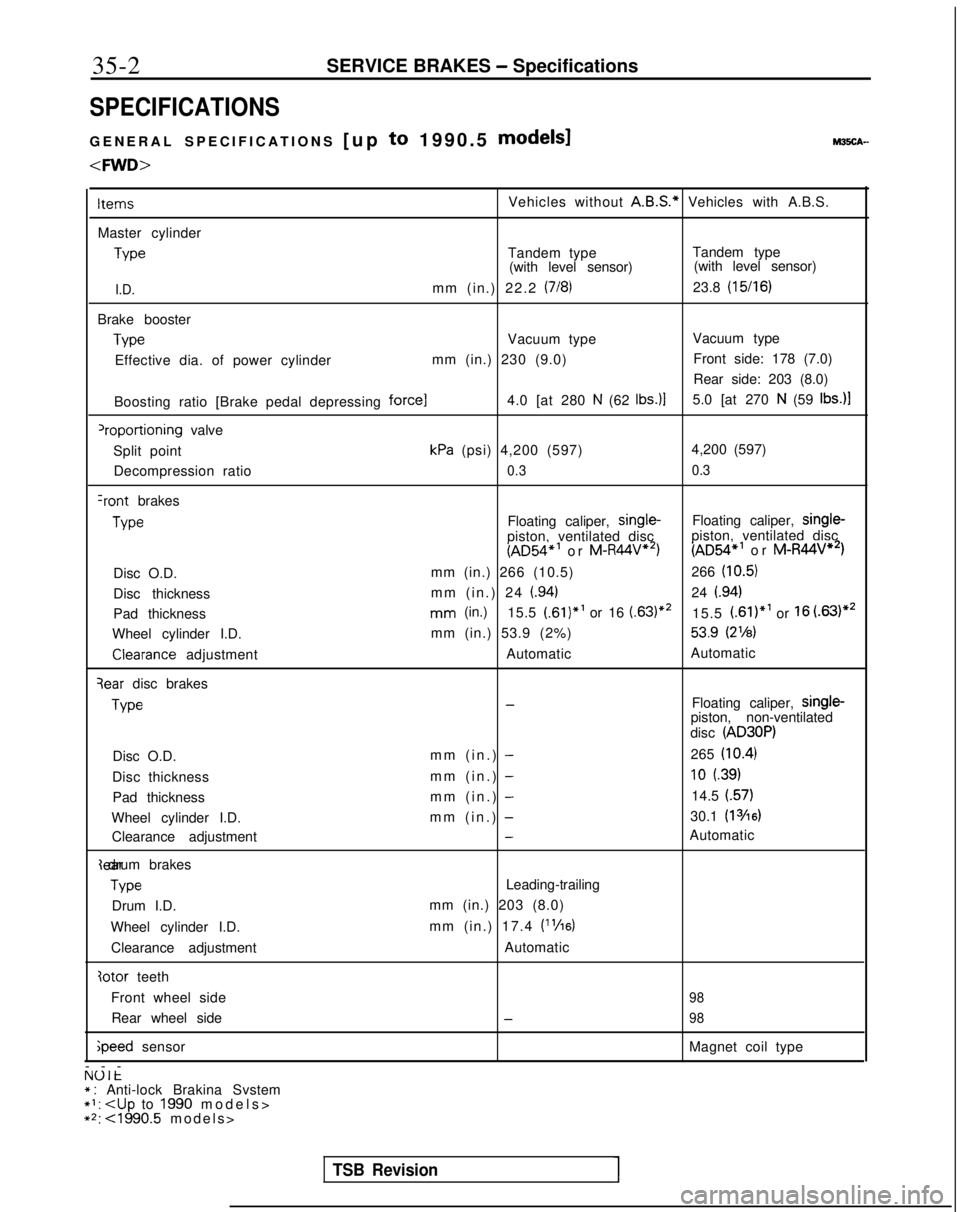
35-2
SERVICE BRAKES - Specifications
SPECIFICATIONS
GENERAL SPECIFICATIONS
[up to 1990.5 models1 M3!iCA-
ItemsVehicles without
A.B.S.*
Vehicles with A.B.S.
Master cylinder Type
Tandem type
Tandem type
(with level sensor) (with level sensor)
I.D.mm (in.) 22.2 (718)23.8 (15/16)
Brake boosterType
Vacuum type
Vacuum type
Effective dia. of power cylinder mm (in.) 230 (9.0)Front side: 178 (7.0)
Rear side: 203 (8.0)
Boosting ratio [Brake pedal depressing
force14.0 [at 280 N (62 tbs.)]5.0 [at 270 N (59 Ibs.)l
‘roportioning valve
Split point
kPa (psi) 4,200 (597) 4,200 (597)
Decompression ratio
0.3 0.3
Iront brakesType
Floating caliper, single-
Floating caliper, single-
piston, ventilated disc
(AD54*’ or M-R44V”‘)piston, ventilated disc (AD54*’
or M-R44V**)
Disc O.D. mm (in.) 266 (10.5)
266
(10.5)
Disc thickness mm (in.) 24 (.94)24 i.94)
Pad thicknessmm (in.)
15.5 (.61)*’ or 16 (63)“’15.5 (.61)*’ or 16 (.63)**
Wheel cylinder I.D. mm (in.) 53.9 (2%)
53.9 (2’/8)Clearance
adjustment AutomaticAutomatic
qear disc brakesType
-Floating caliper, single-
piston, non-ventilated
disc
(AD30P)
Disc O.D. mm (in.) -265 (10.4)
Disc thickness
mm (in.) -10 (.39)
Pad thicknessmm (in.) -14.5 (.57)
Wheel cylinder I.D. mm (in.) -30.1 (13/16)
Clearance adjustment-Automatic{ear drum brakes
Type
Leading-trailing
Drum I.D. mm (in.) 203 (8.0)
Wheel cylinder I.D. mm (in.) 17.4
V’/16)
Clearance adjustment
Automatic
Iotor teeth
Front wheel side
98
Rear wheel side-98 ;peed
sensor Magnet coil type
---
NUlt* : Anti-lock Brakina Svstem*I:
+2: ~1990.5 models
>
TSB RevisionI
Page 1124 of 1273
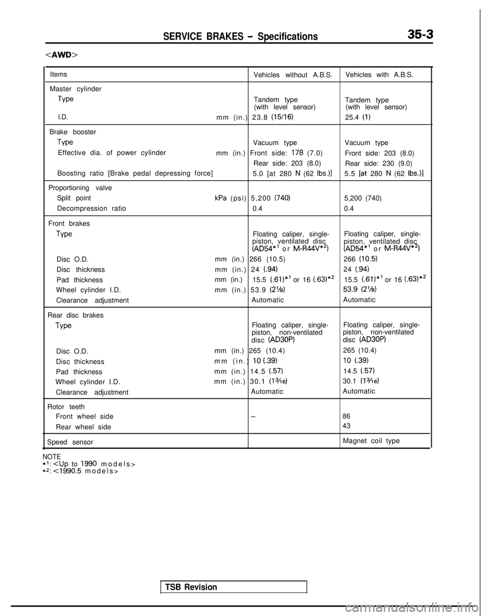
SERVICE BRAKES - Specifications35-3
Items
Vehicles without A.B.S.Vehicles with A.B.S.
Master cylinder Type
Tandem type
Tandem type
(with level sensor) (with level sensor)
I.D.mm (in.) 23.8 (15/16)25.4 (I)
Brake boosterType
Vacuum type
Vacuum type
Effective dia. of power cylinder mm (in.) Front side:
178 (7.0)Front side: 203 (8.0)
Rear side: 203 (8.0) Rear side: 230 (9.0)
Boosting ratio [Brake pedal depressing force] 5.0 [at 280
N (62 Ibs.)]5.5 Iat
280 N (62 Ibs.)]
Proportioning valve Split point
kPa (psi) 5,200 (740)5,200 (740)
Decompression ratio 0.40.4
Front brakes Type
Floating caliper, single-
Floating caliper, single-
piston, ventilated disc
(AD54”’ or M-R44V**)
piston, ventilated disc(AD54*’ or M-R44V**)
Disc O.D. mm (in.) 266 (10.5)
266
(10.5)
Disc thickness mm (in.) 24 (.94)24 (.94)
Pad thicknessmm (in.)
15.5 (.61)*’ or 16 (.63)*’15.5 f.61)“’ or 16 (.63)*2
Wheel cylinder I.D. mm (in.) 53.9 (2%) 53.9
(2%)
Clearance adjustment
Automatic
Automatic
Rear disc brakes Type
Floating caliper, single-
Floating caliper, single-
piston, non-ventilated piston, non-ventilated
disc
(AD30P)disc (AD30P)
Disc O.D. mm (in.) 265 (10.4)
265 (10.4)
Disc thickness mm (in.)
10 L39)10 (.39)
Pad thickness
mm (in.) 14.5 f.57)14.5 (.57)
Wheel cylinder I.D. mm (in.) 30.1 (13/16)30.1 (13/16)
Clearance adjustment Automatic
Automatic
Rotor teeth Front wheel side
-86
Rear wheel side 43
Speed sensor Magnet coil type
NOTE+‘:
**: <1990.5 models
>
TSB Revision
Page 1125 of 1273
![MITSUBISHI GALANT 1989 Service Repair Manual 35-4SERVICE BRAKES - Specifications
GENERAL SPECIFICATIONS [Up to 1992 models]
<fYVD>
Vehicles without A.B.S.
ItemsVehicles with A.B.S.SOHCDOHC
Master cylinderType
Tandem type
Tandem type
Tandem type
MITSUBISHI GALANT 1989 Service Repair Manual 35-4SERVICE BRAKES - Specifications
GENERAL SPECIFICATIONS [Up to 1992 models]
<fYVD>
Vehicles without A.B.S.
ItemsVehicles with A.B.S.SOHCDOHC
Master cylinderType
Tandem type
Tandem type
Tandem type](/manual-img/19/57312/w960_57312-1124.png)
35-4SERVICE BRAKES - Specifications
GENERAL SPECIFICATIONS [Up to 1992 models]
Vehicles without A.B.S.
ItemsVehicles with A.B.S.SOHCDOHC
Master cylinderType
Tandem type
Tandem type
Tandem type
(with level sensor) (with level sensor)(with level sensor)
I.D.mm (in.) 22.2 (7/8)23.8 (15/l 6)
25.4 (I)
Brake booster Type
Vacuum type
Vacuum type
Vacuum type
Effective dia. of power cylinder Front side: 178
(7.0)mm (in.) 230 (9.0)230 (9.0)
Rear side: 203 (8.0)
Boosting ratio 4.05.05.5[Brake pedal depressing force]
[at 280 N (62 Ibs.)][at 220 N (48 Ibs.)][at 250 N (55 Ibs.11
Proportioning valve
Split point
kPa (psi) 4,200 (597)3,700 (526) 3,700 (526)
Decompression ratio0.4 0.30.3
Front brakes Type
Floating caliper, single-
Floating caliper, single-
F!oating caliper, single
piston, ventilated disc y$or&entrlated disc
r;;;6ventrlated drsc(MR44V)
Disc O.D. mm (in.) 256 (10.1)256 (10.1)256 (10.1)
Disc thickness mm (in.) 24
(.94)24 (.94)24 (.94)
Pad thicknessmm (in.) 16 (.63)16 (63)16 (.63)
Wheel cylinder I.D.
mm (in.) 53.9 (2%)60.3 (z3/8)60.3 (23/8)
Clearance adjustment AutomaticAutomatic
Automatic
Rear disc brakes Type
-Floating caliper, single-
piston, non-ventilated Floating caliper, single
piston, non-ventilated
disc
(AD35P)disc (AD35P)
Disc O.D. mm (in.) -265 (10.4)265 (10.4)
Disc thickness mm (in.)
- IO
i.39)
10 (.39)
Pad thickness
mm (in.) -14.5 (57)14.5 (.57)
Wheel cylinder I.D. mm (in.) - 34.9
u3h)34.9 (1%)
Clearance adjustment-Automatic Automatic
Rear drum brakes Type
Leading-trailing
-
Drum I.D.
mm (in.) 203 (8.0)
Wheel cylinder I.D.
mm (in.) 17.4 (‘l/16)--
Clearance adjustment Automatic--3otor
teeth
Front wheel side
98”. 43’2
Rear wheel side--98”. 43’2
speed sensor--Magnet coil type
NOTEl l: 1991 modelsl ? 1992 models
TSB Revision