1989 MITSUBISHI GALANT oil level
[x] Cancel search: oil levelPage 56 of 1273
11-6
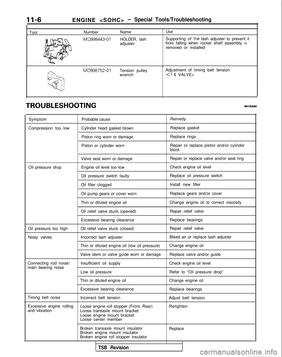
ToolENGINE
-Special Tools/Troubleshooting
Number
NameUse
M
D998443-01 HOLDER, lashSupporting of the lash adjuster to prevent it
adjuster from falling when rocker shaft assembly
IS
removed or installed MD998752-01
Tension pulley Adjustment of timing belt tension
wrench
TROUBLESHOOTINGMHEAAK
Symptom
Compression too low Probable cause
Cylinder head gasket blown Piston ring worn or damage
Piston or cylinder worn Remedy
Replace gasket
Replace rings
Repair or replace piston and/or cylinder
block
Valve seat worn or damage Repair or replace valve and/or seat ring
Oil pressure drop Engine oil level too low Check engine oil level
Oil pressure switch faulty Replace oil pressure switch
Oil filter clogged Install new filter
Oil pump gears or cover worn Replace gears and/or cover
Thin or diluted engine oil Change engine oil to correct viscosity
Oil relief valve stuck (opened) Repair relief valve
Excessive bearing clearance Replace bearings
Oil pressure too high Oil relief valve stuck (closed) Repair relief valve
Noisy valves Incorrect lash adjuster Bleed air or replace lash adjuster
Thin or diluted engine oil (low oil pressure) Change engine oil
Valve stem or valve guide worn or damage Replace valve and/or guide
Connecting rod noise/ Insufficient oil supply Check engine oil level
main bearing noise
Low oil pressure Refer to “Oil pressure drop”
Thin or diluted engine oil Change engine oil
Excessive bearing clearance Replace bearings
Timing belt noise Incorrect belt tension Adjust belt tension
Excessive engine rolling Loose engine roll stopper (Front, Rear)
and vibration Retighten
Loose transaxle mount bracket
Loose engine mount bracket
Loose center member
Broken transaxle mount insulator
Broken engine mount insulator
Broken engine roll stopper insulator Replace
TSB Revision
Page 57 of 1273
ENGINE
OlR0340
1
SERVICE ADJUSTMENT PROCEDU$$o
ENGINE OIL CHECK
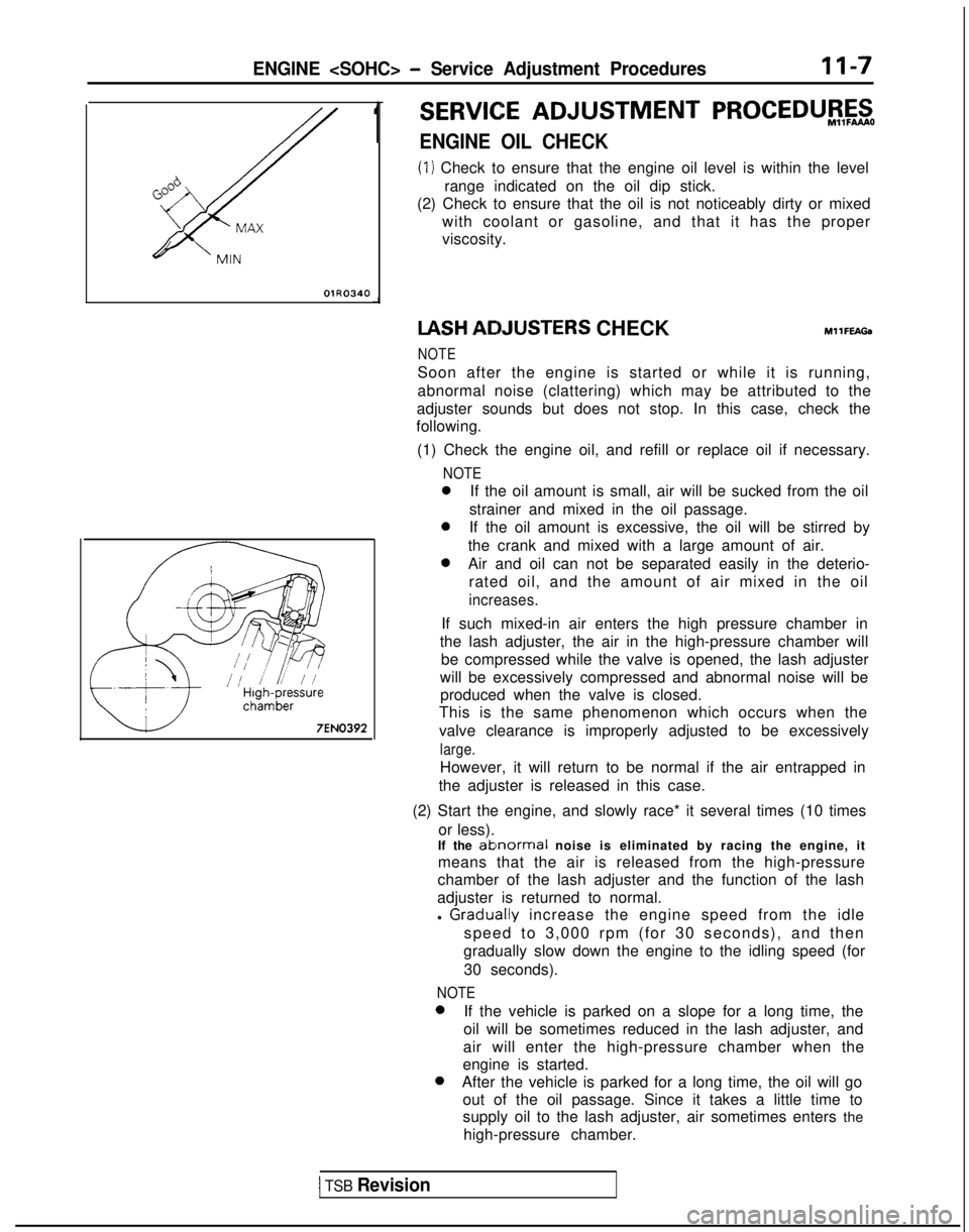
(1) Check to ensure that the engine oil level is within the level
range indicated on the oil dip stick.
(2) Check to ensure that the oil is not noticeably dirty or mixed
with coolant or gasoline, and that it has the proper
viscosity. IASH
ACIJUSTERS CHECKMllFEAGa
NOTE
Soon after the engine is started or while it is running,
abnormal noise (clattering) which may be attributed to the
adjuster sounds but does not stop. In this case, check the
following.
(1) Check the engine oil, and refill or replace oil if necessary.
NOTE
0If the oil amount is small, air will be sucked from the oil
strainer and mixed in the oil passage.
0If the oil amount is excessive, the oil will be stirred by
the crank and mixed with a large amount of air.
0Air and oil can not be separated easily in the deterio- rated oil, and the amount of air mixed in the oil
increases.
If such mixed-in air enters the high pressure chamber in
the lash adjuster, the air in the high-pressure chamber will be compressed while the valve is opened, the lash adjuster
will be excessively compressed and abnormal noise will be produced when the valve is closed.
This is the same phenomenon which occurs when the
valve clearance is improperly adjusted to be excessively
large.
However, it will return to be normal if the air entrapped in
the adjuster is released in this case.
(2) Start the engine, and slowly race* it several times (10 times or less).
If the
ablnormal noise is eliminated by racing the engine, it
means that the air is released from the high-pressure
chamber of the lash adjuster and the function of the lash
adjuster is returned to normal.
l
Graclually increase the engine speed from the idle
speed to 3,000 rpm (for 30 seconds), and then
gradually slow down the engine to the idling speed (for
30 seconds).
NOTE 0
If the vehicle is parked on a slope for a long time, the
oil will be sometimes reduced in the lash adjuster, and
air will enter the high-pressure chamber when the
engine is started. 0
After the vehicle is parked for a long time, the oil will go
out of the oil passage. Since it takes a little time to
supply oil to the lash adjuster, air sometimes enters the
high-pressure chamber.
1 TSB Revision
Page 107 of 1273
ENGINE
OlR0340
7EN0393
1SERVICE ADJUSTMENT PROCEDUBFzo
ENGINE OIL CHECK
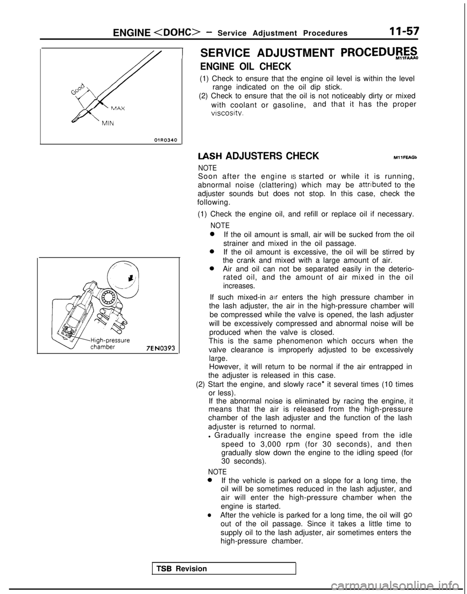
(1) Check to ensure that the engine oil level is within the level
range indicated on the oil dip stick.
(2) Check to ensure that the oil is not noticeably dirty or mixed
with coolant or gasoline, and that it has the proper
vtscosity. IASH
ADJUSTERS CHECK
NOTE MllFEAGb
Soon after the engine IS started or while it is running,
abnormal noise (clattering) which may be attributed
to the
adjuster sounds but does not stop. In this case, check the
following.
(1) Check the engine oil, and refill or replace oil if necessary.
NOTE 0
If the oil amount is small, air will be sucked from the oil
strainer and mixed in the oil passage. 0
If the oil amount is excessive, the oil will be stirred by
the crank and mixed with a large amount of air. 0
Air and oil can not be separated easily in the deterio-
rated oil, and the amount of air mixed in the oil
increases.
If such mixed-in air enters the high pressure chamber in
the lash adjuster, the air in the high-pressure chamber will
be compressed while the valve is opened, the lash adjuster
will be excessively compressed and abnormal noise will be produced when the valve is closed.
This is the same phenomenon which occurs when the
valve clearance is improperly adjusted to be excessively
large.
However, it will return to be normal if the air entrapped in
the adjuster is released in this case.
(2) Start the engine, and slowly
race* it several times (10 times
or less). If the abnormal noise is eliminated by racing the engine, it
means that the air is released from the high-pressure
chamber of the lash adjuster and the function of the lash adluster
is returned to normal.
l Gradually increase the engine speed from the idle
speed to 3,000 rpm (for 30 seconds), and then
gradually slow down the engine to the idling speed (for
30 seconds).
NOTE 0
If the vehicle is parked on a slope for a long time, the
oil will be sometimes reduced in the lash adjuster, and
air will enter the high-pressure chamber when the
engine is started.
lAfter the vehicle is parked for a long time, the oil will go
out of the oil passage. Since it takes a little time to
supply oil to the lash adjuster, air sometimes enters the
high-pressure chamber.
TSR Revision
Page 224 of 1273
13-82 FUEL SYSTEM
OPERATION
l The power-steering pressure switch functions
to convert data as to whether there is or is not apower steering load to LOW-or HIGH-level vol-
tage, and the resulting signals are input to the engine control module. The engine control mod-
ule, based upon those signals, regulates the
idle-speed control motor. l The battery voltage within the engine control
module is applied, by way of the resistance, to
the power-steering pressure switch. When
steering maneuvers are made, the pressure of
the power-steering oil increases, thus switching
ON the power-steering pressure switch, with
the result that the current is grounded. As a re-
sult, the power-steering pressure switch vol-
tage changes from HIGH level to LOW level.
INSPECTION I) Using Scan tool
Function
Item No.
Data reading 27
Data displayInspection conditions Steering wheelNormal indication
Switch status Engine: IdlingSteering wheel idle stateOFF
During steering wheelONoperation
(2) Checking Oil Pressure
Steering wheel
Straight forward
Turned
Oil pump delivery pressure (ref. value)
less than 1,470- 1,961 kPa (213-284 psi)
more than
1,470- 1,961 kPa (213-284 psi)
HARNESS INSPECTION
I-E-I
Harness side connector 6 0
@=- -0
Q
4 1
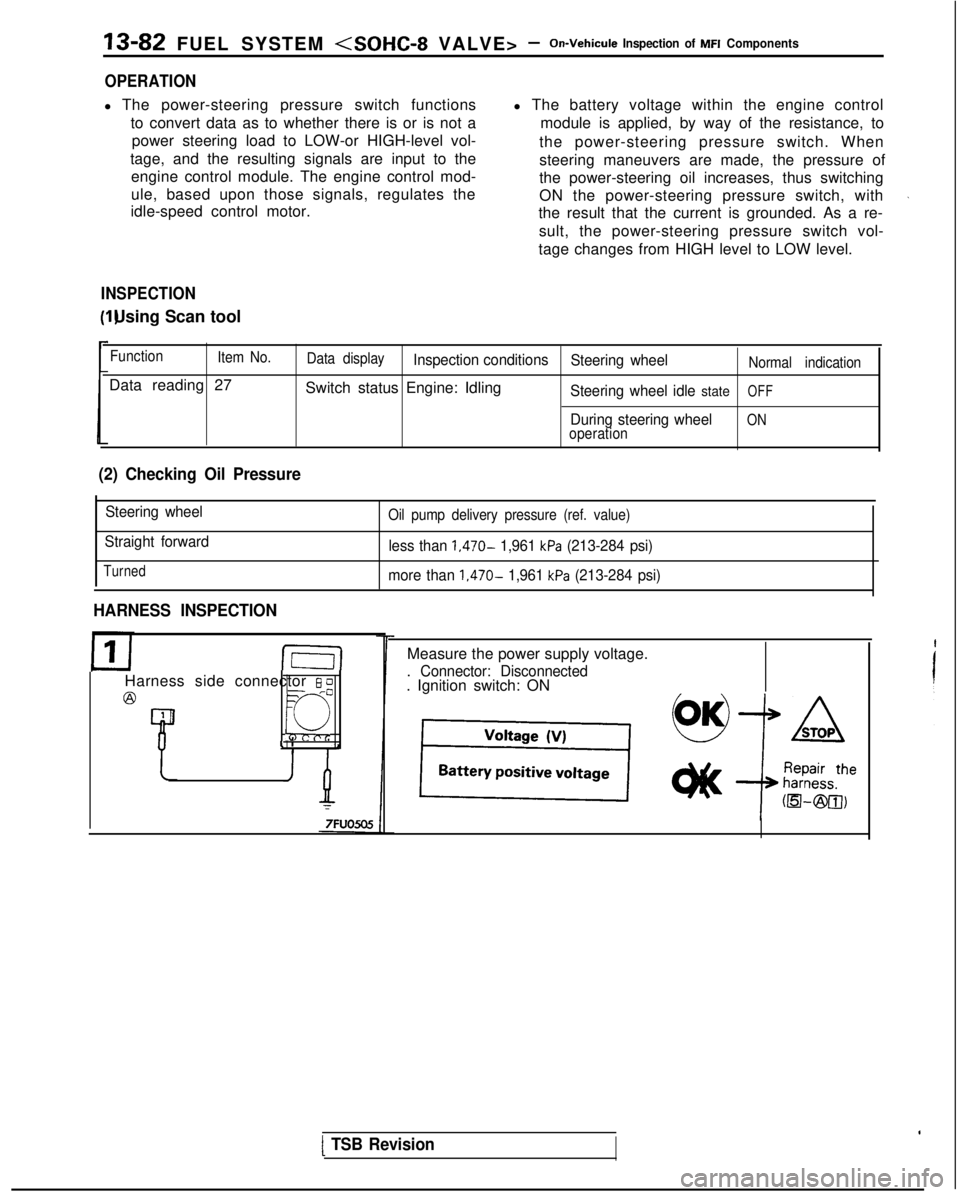
Measure the power supply voltage.
. Connector: Disconnected. Ignition switch: ON
[ TSB Revision
Page 545 of 1273
AUTO-CRUISE CONTROL SYSTEM - Service Adjustment procedures13-403
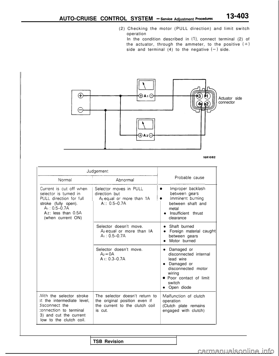
(2) Checking the motor (PULL direction) and limit switch
operation
In the condition described in
(1). connect terminal (2) of
the actuator, through the ammeter, to the positive
(+)
side and terminal (4) to the negative (-) side.
Actuator side
connector
16R1082
~1 L-E~~~~~~
stroke (fully open). A:: 0.5-0.7Abetween shaft andAI : 0.5-0.7Ametal
A Z: less than 0.5A
l Insufficient thrust
(when current ON) clearance
Selector doesn’t move. l Shaft burned Azequal
or more than IA l Foreign material
caugt
AI : 0.5-0.7Abetween gears
l Motor burned
Selector doesn’t move. Az=OA
A I:
0.3-0.7A
l Damaged or
disconnected internal
lead wire
l Damaged or disconnected motor
wiring
0 Poor contact of limit
switch
l Open diode
Nith the selector stroke The selector doesn’t return toMalfunciion of clutch3t the intermediate level,
the original position even if
operationdisconnect
the
the current to the clutch coil
(Clutch plate remains
:onnection to terminalis cut. engaged with clutch)
3) and cut the current
low to the clutch coil.
1t
TSB Revision
Page 555 of 1273

COOLING- Specifications14-3
Items Specifications
Engine coolant temperature gauge unit ResistanceAt
70°C (158°F)n 104f13.5
Engine coolant temperature sensor (Engine control) ResistanceAt
20°C (68°F)kQ 2.45 f 0.24
At 80°C (176°F)Q 296+32
Air conditioning engine coolant temperature switch
ON
+ OFF operating temperature“C (“F) 112-118 (234-244
)
Engine coolant temperature switch
(Air conditioning or A/T control)
OFF
+ ON operating temperature“C (“F) 100-104 (212-219
)
Limit
Opening pressure of radiator cap high pressure valvekPa (psi) 65 (9.2)
TORQUE SPECIFICATIONS
MWCG-
ItemsNm ft.lbs.
Radiator upper insulator 9-14
7-10
Reserve tank, bracket installation bolt9-1
4
7-10
Thermosensor to radiator35
25
Automatic transaxle oil coole: hose cramp 4-
6
3-4
Automatic transaxle oil cooler hose mounting bolt 3-5
2-4
Water outlet fitting bolts
17-2012-14
Water inlet fitting bolts
IO-157-10
Engine mount insulator nut (large)60-8043-58
Engine mount insulator nut (small)
\ 30-4022-29
Engine mount bracket to engine
50-6536-47
Bracket between engine mount bracket and engine 17-26
12-19
Water pump installation bolt Bolt head mark “4T”
12-15
9-l 1
Bolt head mark “7T”20-2714-20
dater pump pulley bolt8-106-
7
Jamper pulley, crankshaft pulley20-3014-22
Timing belt front upper cover installation bolt
IO-127-
9
Timing belt front lower cover installation bolt
IO-127-
9
Crankshaft
sprocket installation bolt
110-13080-94
Timing belt B tensioner 15-2211-16
Tension pulley bracket for air conditioning
23-2717-20
Automatic tensioner installation bolt20-2714-20
Tensioner pulley installation bolt43-5531-40
Oil level gauge 12-159-l 1
Front exhaust pipe to exhaust manifold
Front exhaust pipe bracket
30-4022-29
Exhaust manifold cover (A), (B)
9-11
Heat protector
TSB Revision
Page 575 of 1273
COOLING - Water Hose and Water Pipe
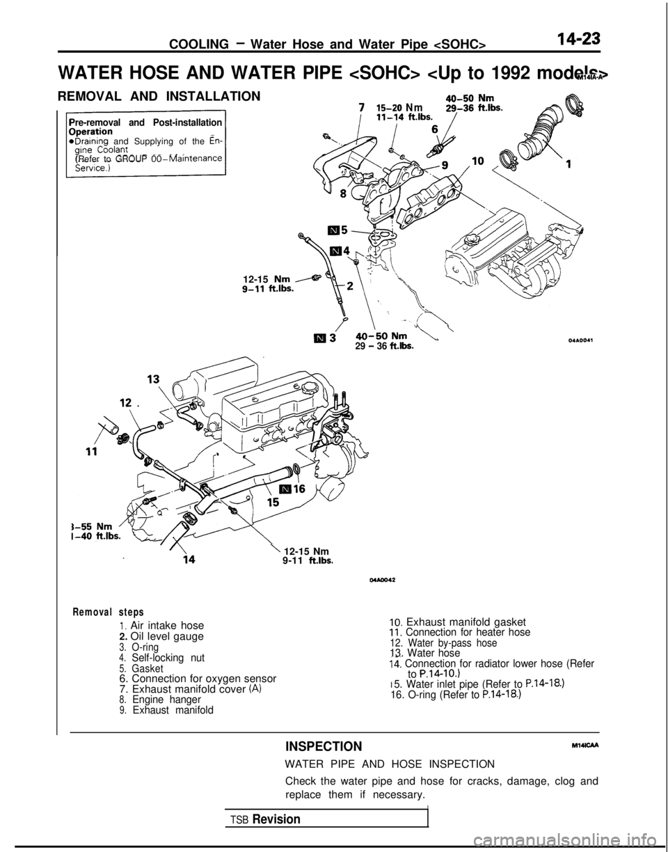
WATER HOSE AND WATER PIPE
REMOVAL AND INSTALLATION
Pre-removal and Post-installation
*Draining and Supplying of the En-
(Refer to GROUP 00-Maintenance
12-15 Nm
g-11
ft.lbs.
715-20 Nm
Ill329 - 36 fths.
\ 12-15 Nm
9-11 ft.lbs.
Mbm42
Removal steps
1. Air intake hose
2. Oil level gauge
3.O-ring4.Self-locking nut5.Gasket6. Connection for oxygen sensor
7. Exhaust manifold cover (A)
8.Engine hanger9.Exhaust manifold
10. Exhaust manifold gasket11. Connection for heater hose12. Water by-pass hose13. Water hosei41 Connection for radiator lower hose (Referto P.14-IO.)I 5. Water inlet pipe (Refer to P.14-18.)16. O-ring (Refer to P.14-18.)
INSPECTIONMl4lcAA
WATER PIPE AND HOSE INSPECTION
Check the water pipe and hose for cracks, damage, clog andreplace them if necessary.
ITSB Revision
Page 590 of 1273
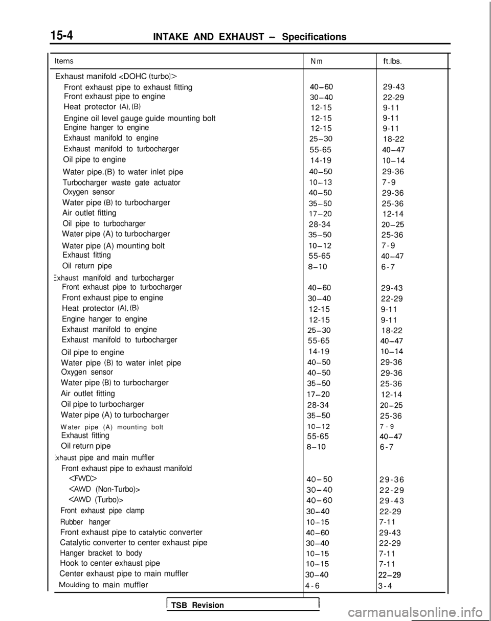
15-4INTAKE AND EXHAUST - Specifications
Items
Exhaust manifold
Front exhaust pipe to exhaust fitting
Front exhaust pipe to engine
Heat protector
(A), (B)
Engine oil level gauge guide mounting bolt
Engine hanger to engine
Exhaust manifold to engine
Exhaust manifold to turbocharger
Oil pipe to engine
Water pipe.(B) to water inlet pipe
Turbocharger waste gate actuator Oxygen sensor
Water pipe (B) to turbocharger
Air outlet fitting
Oil pipe to turbocharger
Water pipe (A) to turbocharger
Water pipe (A) mounting bolt
Exhaust fitting
Oil return pipe
!xhaust manifold and turbocharger
Front exhaust pipe to turbocharger
Front exhaust pipe to engine
Heat protector
(A), (B)
Engine hanger to engine
Exhaust manifold to engine
Exhaust manifold to turbocharger
Oil pipe to engine
Water pipe
(B) to water inlet pipe
Oxygen sensor
Water pipe (B) to turbocharger
Air outlet fitting Oil pipe to turbocharger
Water pipe (A) to turbocharger
W
ater pipe (A) mounting bolt
Exhaust fitting
Oil return pipe
Exhaust pipe and main muffler
Front exhaust pipe to exhaust manifold
Front exhaust pipe clamp
Rubber hanger
Front exhaust pipe to catalytic converter
Catalytic converter to center exhaust pipe
Hanger bracket to body
Hook to center exhaust pipe
Center exhaust pipe to main muffler
Moulding to main muffler
1 TSBRevision
Nm
40-60
30-40
12-15
12-15
12-15
25-30
55-65
14-19
40-50
IO-13
40-50
35-50
17-20
28-34
35-50
IO-12
55-65
8-10
40-60
30-40
12-15
12-15
25-30
55-65
14-19
40-50
40-50
35-50
17-20
28-34
35-50
IO-12
55-65
8-10
40-50
30-40
40-60
30-40
IO-15
40-60
30-40
IO-15
IO-15
30-40
4-
6
1
ft.lbs.
29-43
22-29
9-11
9-11
9-11
18-22
40-47
10-14
29-36
7-
9
29-36
25-36 12-14
20-25
25-36
7-
9
40-47
6-
7
29-43
22-29
9-11
9-11 18-22
40-47
IO-14
29-36
29-36
25-36
12-14
20-25
25-36
7-
9
40-47
6-
7
29-36
22-29
29-43
22-29
7-11
29-43
22-29
7-11
7-11
22-29
3-
4