1989 FORD FIESTA engine coolant
[x] Cancel search: engine coolantPage 100 of 296
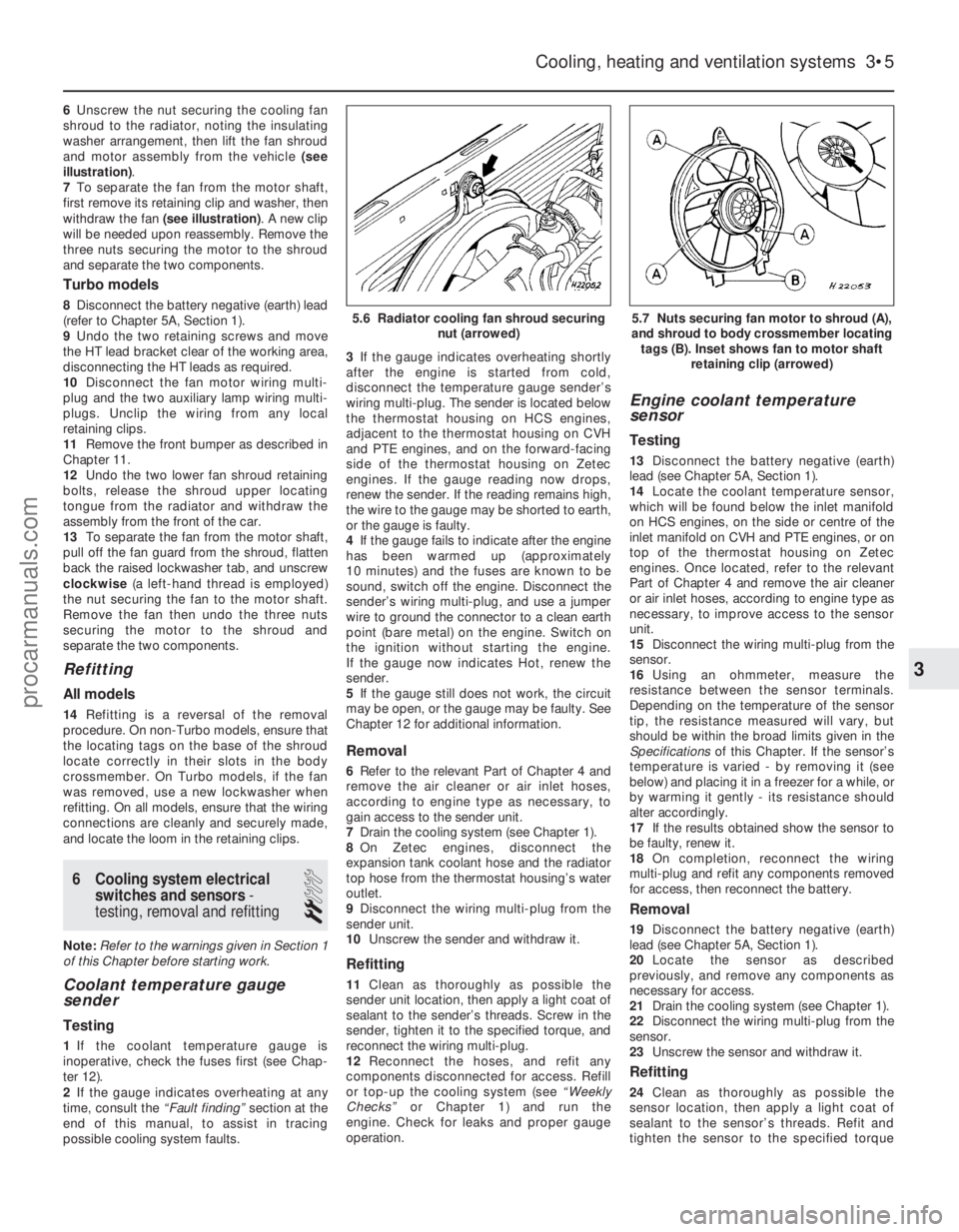
6Unscrew the nut securing the cooling fan
shroud to the radiator, noting the insulating
washer arrangement, then lift the fan shroud
and motor assembly from the vehicle (see
illustration) .
7 To separate the fan from the motor shaft,
first remove its retaining clip and washer, then
withdraw the fan (see illustration) . A new clip
will be needed upon reassembly. Remove the
three nuts securing the motor to the shroud
and separate the two components.
Turbo models
8 Disconnect the battery negative (earth) lead
(refer to Chapter 5A, Section 1).
9 Undo the two retaining screws and move
the HT lead bracket clear of the working area,
disconnecting the HT leads as required.
10 Disconnect the fan motor wiring multi-
plug and the two auxiliary lamp wiring multi-
plugs. Unclip the wiring from any local
retaining clips.
11 Remove the front bumper as described in
Chapter 11.
12 Undo the two lower fan shroud retaining
bolts, release the shroud upper locating
tongue from the radiator and withdraw the
assembly from the front of the car.
13 To separate the fan from the motor shaft,
pull off the fan guard from the shroud, flatten
back the raised lockwasher tab, and unscrew
clockwise (a left-hand thread is employed)
the nut securing the fan to the motor shaft.
Remove the fan then undo the three nuts
securing the motor to the shroud and
separate the two components.
Refitting
All models
14 Refitting is a reversal of the removal
procedure. On non-Turbo models, ensure that
the locating tags on the base of the shroud
locate correctly in their slots in the body
crossmember. On Turbo models, if the fan
was removed, use a new lockwasher when
refitting. On all models, ensure that the wiring
connections are cleanly and securely made,
and locate the loom in the retaining clips.
6 Cooling system electrical switches and sensors -
testing, removal and refitting
2
Note: Refer to the warnings given in Section 1
of this Chapter before starting work.
Coolant temperature gauge
sender
Testing
1 If the coolant temperature gauge is
inoperative, check the fuses first (see Chap-
ter 12).
2 If the gauge indicates overheating at any
time, consult the “Fault finding” section at the
end of this manual, to assist in tracing
possible cooling system faults. 3
If the gauge indicates overheating shortly
after the engine is started from cold,
disconnect the temperature gauge sender’s
wiring multi-plug. The sender is located below
the thermostat housing on HCS engines,
adjacent to the thermostat housing on CVH
and PTE engines, and on the forward-facing
side of the thermostat housing on Zetec
engines. If the gauge reading now drops,
renew the sender. If the reading remains high,
the wire to the gauge may be shorted to earth,
or the gauge is faulty.
4 If the gauge fails to indicate after the engine
has been warmed up (approximately
10 minutes) and the fuses are known to be
sound, switch off the engine. Disconnect the
sender’s wiring multi-plug, and use a jumper
wire to ground the connector to a clean earth
point (bare metal) on the engine. Switch on
the ignition without starting the engine.
If the gauge now indicates Hot, renew the
sender.
5 If the gauge still does not work, the circuit
may be open, or the gauge may be faulty. See
Chapter 12 for additional information.
Removal
6 Refer to the relevant Part of Chapter 4 and
remove the air cleaner or air inlet hoses,
according to engine type as necessary, to
gain access to the sender unit.
7 Drain the cooling system (see Chapter 1).
8 On Zetec engines, disconnect the
expansion tank coolant hose and the radiator
top hose from the thermostat housing’s water
outlet.
9 Disconnect the wiring multi-plug from the
sender unit.
10 Unscrew the sender and withdraw it.
Refitting
11Clean as thoroughly as possible the
sender unit location, then apply a light coat of
sealant to the sender’s threads. Screw in the
sender, tighten it to the specified torque, and
reconnect the wiring multi-plug.
12 Reconnect the hoses, and refit any
components disconnected for access. Refill
or top-up the cooling system (see “Weekly
Checks” or Chapter 1) and run the
engine. Check for leaks and proper gauge
operation.
Engine coolant temperature
sensor
Testing
13 Disconnect the battery negative (earth)
lead (see Chapter 5A, Section 1).
14 Locate the coolant temperature sensor,
which will be found below the inlet manifold
on HCS engines, on the side or centre of the
inlet manifold on CVH and PTE engines, or on
top of the thermostat housing on Zetec
engines. Once located, refer to the relevant
Part of Chapter 4 and remove the air cleaner
or air inlet hoses, according to engine type as
necessary, to improve access to the sensor
unit.
15 Disconnect the wiring multi-plug from the
sensor.
16 Using an ohmmeter, measure the
resistance between the sensor terminals.
Depending on the temperature of the sensor
tip, the resistance measured will vary, but
should be within the broad limits given in the
Specifications of this Chapter. If the sensor’s
temperature is varied - by removing it (see
below) and placing it in a freezer for a while, or
by warming it gently - its resistance should
alter accordingly.
17 If the results obtained show the sensor to
be faulty, renew it.
18 On completion, reconnect the wiring
multi-plug and refit any components removed
for access, then reconnect the battery.
Removal
19 Disconnect the battery negative (earth)
lead (see Chapter 5A, Section 1).
20 Locate the sensor as described
previously, and remove any components as
necessary for access.
21 Drain the cooling system (see Chapter 1).
22 Disconnect the wiring multi-plug from the
sensor.
23 Unscrew the sensor and withdraw it.
Refitting
24Clean as thoroughly as possible the
sensor location, then apply a light coat of
sealant to the sensor’s threads. Refit and
tighten the sensor to the specified torque
Cooling, heating and ventilation systems 3•5
5.7 Nuts securing fan motor to shroud (A),
and shroud to body crossmember locating tags (B). Inset shows fan to motor shaft retaining clip (arrowed)5.6 Radiator cooling fan shroud securing nut (arrowed)
3
1595Ford Fiesta Remakeprocarmanuals.com
http://vnx.su
Page 101 of 296
wrench setting, and reconnect the multi-plug.
25Refit any components disconnected for
access then refill the cooling system (see
Chapter 1).
Radiator electric cooling fan
thermostatic switch
Testing
26 Refer to the procedures contained in
Section 5.
Removal
27 Disconnect the battery negative (earth)
lead (refer to Chapter 5A, Section 1).
28 Drain the cooling system (see Chapter 1).
29 Disconnect the wiring multi-plug from the
thermostatic switch, and then unscrew the
switch from the thermostat housing or
radiator side tank, as applicable. Remove the
sealing washer.
Refitting
30 Refitting is a reversal of removal, but fit a
new sealing washer and tighten the switch
securely. Refill the cooling system as
described in Chapter 1, then reconnect the
battery.
7 Radiator and expansion tank
- removal, inspection and
refitting
2
Note: Refer to the warnings given in Section 1
of this Chapter before starting work.
Radiator
Removal (all models except Turbo)
1 Disconnect the battery negative (earth) lead
(refer to Chapter 5A, Section 1).
2 Drain the cooling system (see Chapter 1).
3 Remove the radiator cooling fan assembly
as described in Section 5.
4 Release the hose clips and disconnect the
hoses from the radiator. Additionally, on automatic transmission models, disconnect
the transmission fluid cooling pipe
connections fitting blanking plugs to prevent
excessive fluid loss
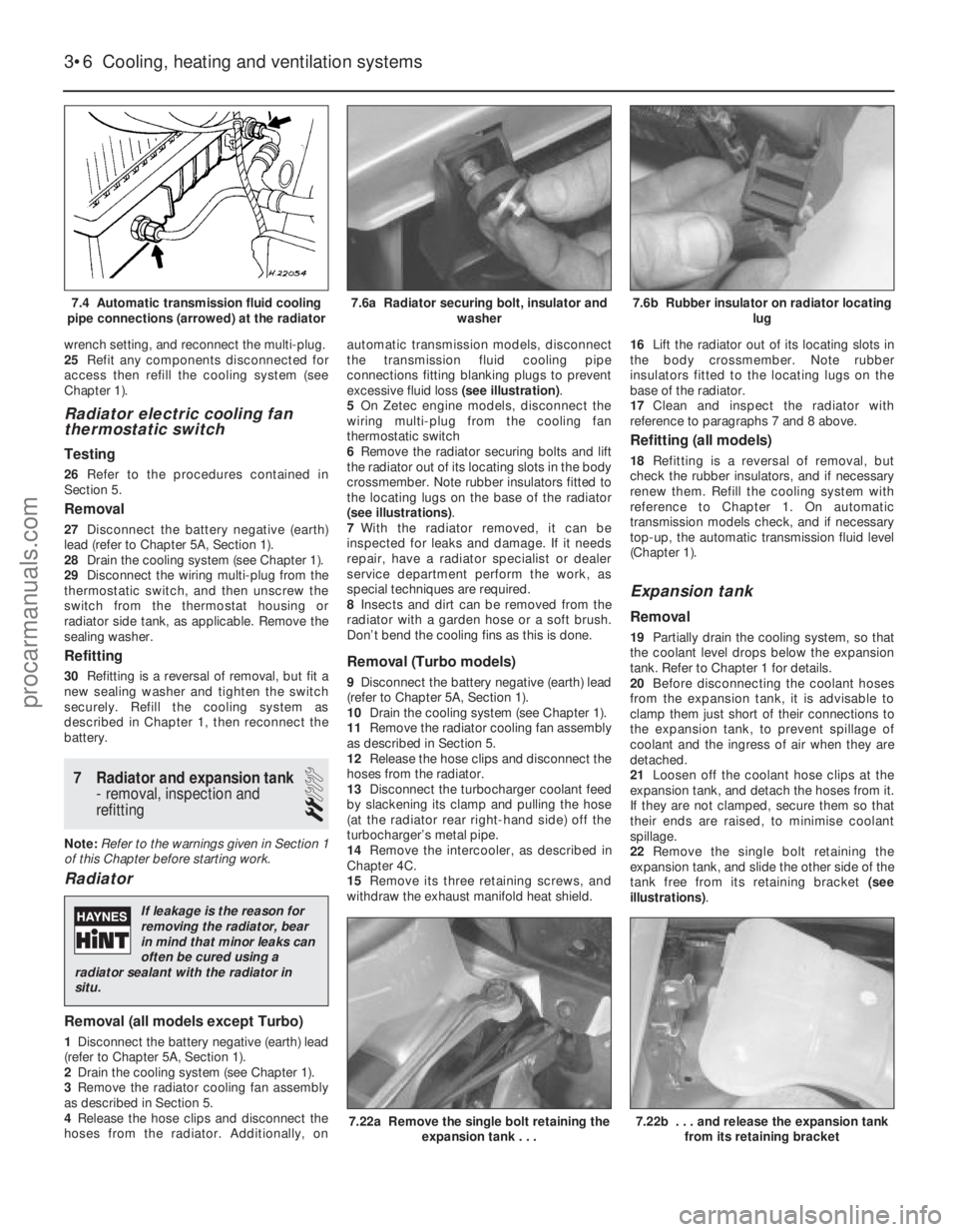
(see illustration).
5 On Zetec engine models, disconnect the
wiring multi-plug from the cooling fan
thermostatic switch
6 Remove the radiator securing bolts and lift
the radiator out of its locating slots in the body
crossmember. Note rubber insulators fitted to
the locating lugs on the base of the radiator
(see illustrations) .
7 With the radiator removed, it can be
inspected for leaks and damage. If it needs
repair, have a radiator specialist or dealer
service department perform the work, as
special techniques are required.
8 Insects and dirt can be removed from the
radiator with a garden hose or a soft brush.
Don’t bend the cooling fins as this is done.
Removal (Turbo models)
9 Disconnect the battery negative (earth) lead
(refer to Chapter 5A, Section 1).
10 Drain the cooling system (see Chapter 1).
11 Remove the radiator cooling fan assembly
as described in Section 5.
12 Release the hose clips and disconnect the
hoses from the radiator.
13 Disconnect the turbocharger coolant feed
by slackening its clamp and pulling the hose
(at the radiator rear right-hand side) off the
turbocharger’s metal pipe.
14 Remove the intercooler, as described in
Chapter 4C.
15 Remove its three retaining screws, and
withdraw the exhaust manifold heat shield. 16
Lift the radiator out of its locating slots in
the body crossmember. Note rubber
insulators fitted to the locating lugs on the
base of the radiator.
17 Clean and inspect the radiator with
reference to paragraphs 7 and 8 above.
Refitting (all models)
18 Refitting is a reversal of removal, but
check the rubber insulators, and if necessary
renew them. Refill the cooling system with
reference to Chapter 1. On automatic
transmission models check, and if necessary
top-up, the automatic transmission fluid level
(Chapter 1).
Expansion tank
Removal
19 Partially drain the cooling system, so that
the coolant level drops below the expansion
tank. Refer to Chapter 1 for details.
20 Before disconnecting the coolant hoses
from the expansion tank, it is advisable to
clamp them just short of their connections to
the expansion tank, to prevent spillage of
coolant and the ingress of air when they are
detached.
21 Loosen off the coolant hose clips at the
expansion tank, and detach the hoses from it.
If they are not clamped, secure them so that
their ends are raised, to minimise coolant
spillage.
22 Remove the single bolt retaining the
expansion tank, and slide the other side of the
tank free from its retaining bracket (see
illustrations) .
3•6Cooling, heating and ventilation systems
7.22b . . . and release the expansion tank
from its retaining bracket7.22a Remove the single bolt retaining the expansion tank . . .
7.6b Rubber insulator on radiator locating lug7.6a Radiator securing bolt, insulator andwasher7.4 Automatic transmission fluid cooling
pipe connections (arrowed) at the radiator
1595Ford Fiesta Remake
If leakage is the reason for
removing the radiator, bear
in mind that minor leaks can
often be cured using a
radiator sealant with the radiator in
situ.
procarmanuals.com
http://vnx.su
Page 102 of 296
Refitting
23Refit in the reverse order of removal. Top-
up the cooling system as described in
“Weekly Checks”.
8 Water pump (HCS engines) -
removal and refitting
2
Note: Refer to the warnings given in Section 1
of this Chapter before starting work.
Removal
1 Disconnect the battery negative (earth) lead
(refer to Chapter 5A, Section 1).
2 Drain the cooling system (see Chapter 1).
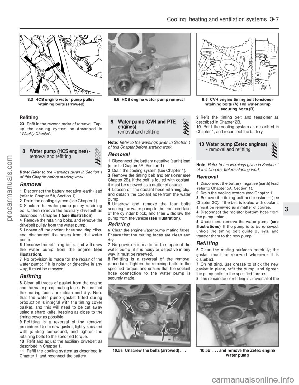
3 Slacken the water pump pulley retaining
bolts, then remove the auxiliary drivebelt as
described in Chapter 1 (see illustration).
4 Remove the retaining bolts, and remove the
drivebelt pulley from the water pump.
5 Loosen off the coolant hose securing clips,
and disconnect the hoses from the water
pump.
6 Unscrew the retaining bolts, and withdraw
the water pump from the engine (see
illustration) .
7 No provision is made for the repair of the
water pump; if it is noisy or defective in any
way, it must be renewed.
Refitting
8 Clean all traces of gasket from the engine
and the water pump mating faces. Ensure that
the mating faces are clean and dry. Note
that the water pump gasket fitted during
production is integral with the timing cover
gasket, and this will need to be cut away
using a sharp knife, keeping as close to the
timing cover as possible.
9 Refitting is a reversal of the removal
procedure. Use a new gasket, lightly smeared
with jointing compound, and tighten the
retaining bolts to the specified torque.
10 Refit and adjust the auxiliary drivebelt as
described in Chapter 1.
11 Refill the cooling system as described in
Chapter 1, and reconnect the battery.
9 Water pump (CVH and PTE engines) -
removal and refitting
4
Note: Refer to the warnings given in Section 1
of this Chapter before starting work.
Removal
1 Disconnect the battery negative (earth) lead
(refer to Chapter 5A, Section 1).
2 Drain the cooling system (see Chapter 1).
3 Remove the timing belt and tensioner (see
Chapter 2B). If the belt is fouled with coolant,
it must be renewed as a matter of course.
4 Loosen off the coolant hose retaining clip,
and detach the coolant hose from the water
pump.
5 Unscrew and remove the four bolts
securing the water pump to the front end face
of the cylinder block, and then withdraw the
pump from the vehicle (see illustration).
Refitting
6Clean the engine water pump mating faces.
Ensure that the mating faces are clean and
dry.
7 No provision is made for the repair of the
water pump; if it is noisy or defective in any
way, it must be renewed.
8 Refitting is a reversal of the removal
procedure. Tighten the retaining bolts to the
specified torque, and ensure that the coolant
hose connection to the water pump is
securely made. 9
Refit the timing belt and tensioner as
described in Chapter 2B.
10 Refill the cooling system as described in
Chapter 1, and reconnect the battery.
10 Water pump (Zetec engines) - removal and refitting
4
Note: Refer to the warnings given in Section 1
of this Chapter before starting work.
Removal
1 Disconnect the battery negative (earth) lead
(refer to Chapter 5A, Section 1).
2 Drain the cooling system (see Chapter 1).
3 Remove the timing belt and tensioner (see
Chapter 2C). If the belt is fouled with coolant,
it must be renewed as a matter of course.
4 Disconnect the radiator bottom hose from
the pump union.
5 Unbolt and remove the water pump (see
illustrations) . If the pump is to be renewed,
unbolt the timing belt guide pulleys, and
transfer them to the new pump.
Refitting
6 Clean the mating surfaces carefully; the
gasket must be renewed whenever it is
disturbed.
7 On refitting, use grease to stick the new
gasket in place, refit the pump, and tighten
the pump bolts to the specified torque.
8 The remainder of refitting is a reversal of the
Cooling, heating and ventilation systems 3•7
9.5 CVH engine timing belt tensioner
retaining bolts (A) and water pump securing bolts (B)8.6 HCS engine water pump removal8.3 HCS engine water pump pulleyretaining bolts (arrowed)
10.5b . . . and remove the Zetec engine water pump10.5a Unscrew the bolts (arrowed) . . .
3
1595Ford Fiesta Remakeprocarmanuals.com
http://vnx.su
Page 103 of 296
removal procedure. Refit the timing belt and
tensioner as described in Chapter 2C, noting
that a new tensioner spring and retaining pin
must be fitted if the timing belt has been
removed for the first time. Tighten all
fasteners to the specified torque, and refill the
system with coolant as described in Chap-
ter 1.
11 Heater/ventilationcomponents -
removal and refitting
3
Heater controls
1 Disconnect the battery negative (earth) lead
(refer to Chapter 5A, Section 1).
2 Refer to Chapter 12 and remove the radio.
3 Pull off the heater fan motor control knob,
then move the air distribution and
temperature controls fully to the right. Unclip
and remove the heater slide facia towards the
left-hand side of the vehicle, removing the
slide control knobs only as necessary, and
disconnecting its bulbholder (bayonet type) as
it is withdrawn.
4 Squeeze the two release tabs together on
the heater fan motor control switch, and
remove it, disconnecting its multi-plug as it is
withdrawn.
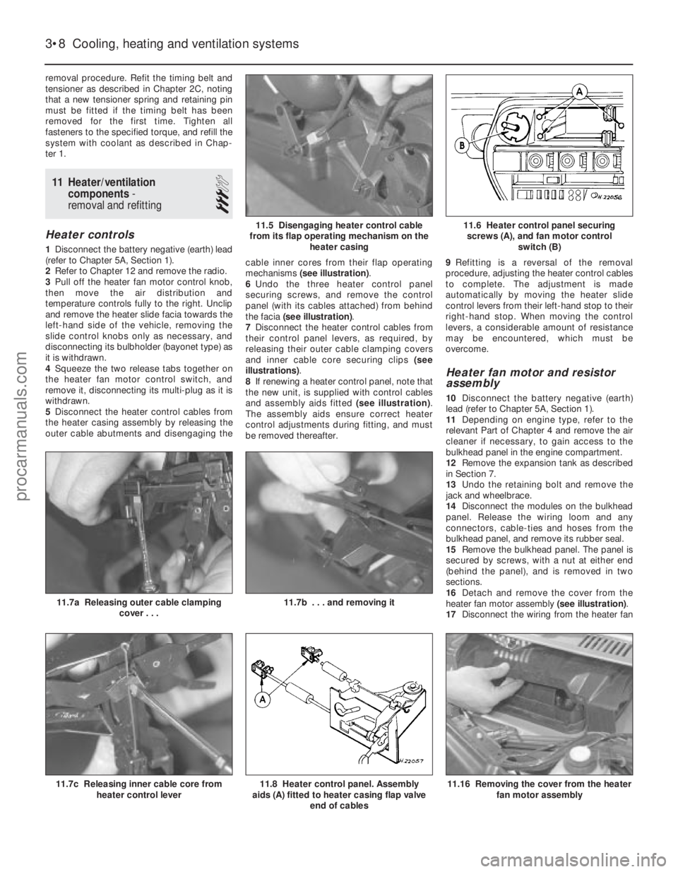
5 Disconnect the heater control cables from
the heater casing assembly by releasing the
outer cable abutments and disengaging the cable inner cores from their flap operating
mechanisms
(see illustration) .
6 Undo the three heater control panel
securing screws, and remove the control
panel (with its cables attached) from behind
the facia (see illustration) .
7 Disconnect the heater control cables from
their control panel levers, as required, by
releasing their outer cable clamping covers
and inner cable core securing clips (see
illustrations) .
8 If renewing a heater control panel, note that
the new unit, is supplied with control cables
and assembly aids fitted (see illustration).
The assembly aids ensure correct heater
control adjustments during fitting, and must
be removed thereafter. 9
Refitting is a reversal of the removal
procedure, adjusting the heater control cables
to complete. The adjustment is made
automatically by moving the heater slide
control levers from their left-hand stop to their
right-hand stop. When moving the control
levers, a considerable amount of resistance
may be encountered, which must be
overcome.
Heater fan motor and resistor
assembly
10 Disconnect the battery negative (earth)
lead (refer to Chapter 5A, Section 1).
11 Depending on engine type, refer to the
relevant Part of Chapter 4 and remove the air
cleaner if necessary, to gain access to the
bulkhead panel in the engine compartment.
12 Remove the expansion tank as described
in Section 7.
13 Undo the retaining bolt and remove the
jack and wheelbrace.
14 Disconnect the modules on the bulkhead
panel. Release the wiring loom and any
connectors, cable-ties and hoses from the
bulkhead panel, and remove its rubber seal.
15 Remove the bulkhead panel. The panel is
secured by screws, with a nut at either end
(behind the panel), and is removed in two
sections.
16 Detach and remove the cover from the
heater fan motor assembly (see illustration).
17 Disconnect the wiring from the heater fan
3•8 Cooling, heating and ventilation systems
11.16 Removing the cover from the heater
fan motor assembly11.8 Heater control panel. Assembly
aids (A) fitted to heater casing flap valve
end of cables11.7c Releasing inner cable core fromheater control lever
11.7b . . . and removing it11.7a Releasing outer cable clamping
cover . . .
11.6 Heater control panel securing screws (A), and fan motor control switch (B)11.5 Disengaging heater control cable
from its flap operating mechanism on the heater casing
1595Ford Fiesta Remakeprocarmanuals.com
http://vnx.su
Page 104 of 296
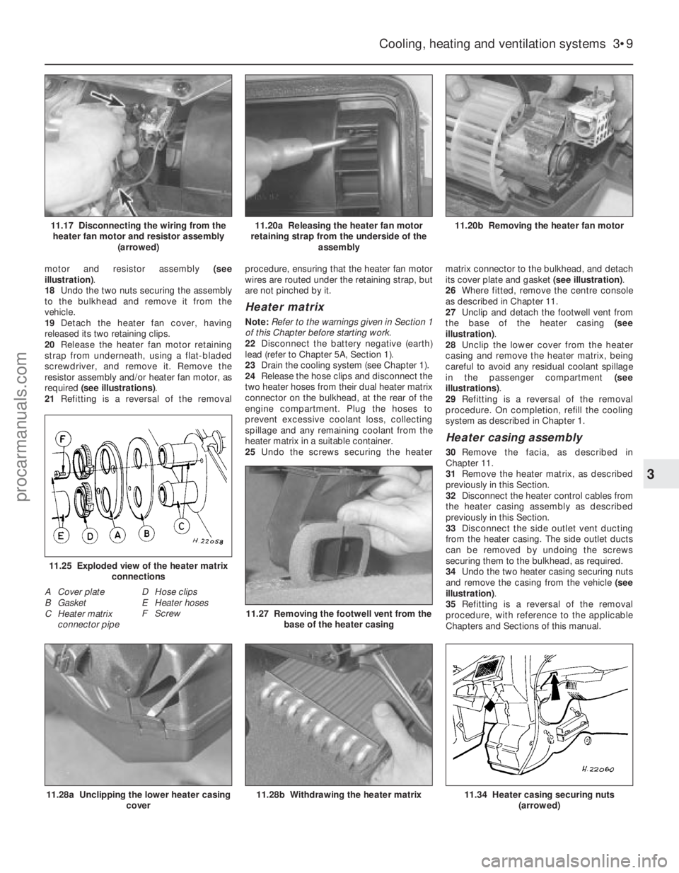
motor and resistor assembly (see
illustration) .
18 Undo the two nuts securing the assembly
to the bulkhead and remove it from the
vehicle.
19 Detach the heater fan cover, having
released its two retaining clips.
20 Release the heater fan motor retaining
strap from underneath, using a flat-bladed
screwdriver, and remove it. Remove the
resistor assembly and/or heater fan motor, as
required (see illustrations) .
21 Refitting is a reversal of the removal procedure, ensuring that the heater fan motor
wires are routed under the retaining strap, but
are not pinched by it.
Heater matrix
Note:
Refer to the warnings given in Section 1
of this Chapter before starting work.
22 Disconnect the battery negative (earth)
lead (refer to Chapter 5A, Section 1).
23 Drain the cooling system (see Chapter 1).
24 Release the hose clips and disconnect the
two heater hoses from their dual heater matrix
connector on the bulkhead, at the rear of the
engine compartment. Plug the hoses to
prevent excessive coolant loss, collecting
spillage and any remaining coolant from the
heater matrix in a suitable container.
25 Undo the screws securing the heater matrix connector to the bulkhead, and detach
its cover plate and gasket
(see illustration).
26 Where fitted, remove the centre console
as described in Chapter 11.
27 Unclip and detach the footwell vent from
the base of the heater casing (see
illustration) .
28 Unclip the lower cover from the heater
casing and remove the heater matrix, being
careful to avoid any residual coolant spillage
in the passenger compartment (see
illustrations) .
29 Refitting is a reversal of the removal
procedure. On completion, refill the cooling
system as described in Chapter 1.
Heater casing assembly
30 Remove the facia, as described in
Chapter 11.
31 Remove the heater matrix, as described
previously in this Section.
32 Disconnect the heater control cables from
the heater casing assembly as described
previously in this Section.
33 Disconnect the side outlet vent ducting
from the heater casing. The side outlet ducts
can be removed by undoing the screws
securing them to the bulkhead, as required.
34 Undo the two heater casing securing nuts
and remove the casing from the vehicle (see
illustration) .
35 Refitting is a reversal of the removal
procedure, with reference to the applicable
Chapters and Sections of this manual.
Cooling, heating and ventilation systems 3•9
11.20b Removing the heater fan motor11.20a Releasing the heater fan motor
retaining strap from the underside of the assembly11.17 Disconnecting the wiring from theheater fan motor and resistor assembly (arrowed)
11.34 Heater casing securing nuts(arrowed)11.28b Withdrawing the heater matrix
11.27 Removing the footwell vent from thebase of the heater casing
11.25 Exploded view of the heater matrix connections
A Cover plate
B Gasket
C Heater matrixconnector pipe D Hose clips
E Heater hoses
F Screw
11.28a Unclipping the lower heater casing
cover
3
1595Ford Fiesta Remakeprocarmanuals.com
http://vnx.su
Page 120 of 296
16Prise out the tamperproof seal covering
the fuel mixture screw, then undo and remove
the mixture screw.
Cleaning and inspection
17 Wash the carburettor components,
drillings and passages with clean petrol, then
blow them dry using a low-pressure air line. A
high-pressure air line must not be applied to
the accelerator pump discharge assembly or
the pump supply valve, as they each contain a
rubber Vernay valve, and these can easily be
damaged under high pressure. Never use a
piece of wire for cleaning purposes.
18 Examine all of the carburettor
components for signs of damage or wear,
paying particular attention to the diaphragms,
throttle spindle and plates, needle valve and
mixture screw; the power valve jet is adjacent
to the primary main jet. Renew all
diaphragms, sealing washers and gaskets as
a matter of course.
Reassembly
19 Refit the fuel mixture screw by fully
winding the screw in, then unwinding three
turns to give an approximate setting.
20 Refit the power valve assembly ensuring
that the diaphragm lies flat, and that the
vacuum gallery lines up correctly with the
diaphragm and housing.
21 Reassemble the secondary barrel
diaphragm into its housing, ensuring that
the diaphragm lies flat and that the vacuum
gallery lines up with the diaphragm and
housing. Also, to assist with installation, do
not reconnect its operating rod until the cover
has been secured.
22 Refit the throttle kicker mounting bracket.
23 Refit the anti-dieseling (fuel cut-off)
solenoid, using a new sealing washer.
24 Refit the accelerator pump assembly,
ensuring that the diaphragm lies flat and is not
kinked.
25 Reassemble the throttle kicker, ensuring
that the diaphragm lies flat and that the relative position of the diaphragm operating
link to the throttle kicker cover is correct. Fully
attach the throttle kicker assembly.
26
Refit the main and idle jets, making
reference to the notes taken during
dismantling to ensure correct fitted locations.
27 Reassemble the carburettor upper body
as described in the following paragraphs.
28 Refit the needle valve housing (using a
new washer if applicable).
29 Refit the needle valve and float assembly,
having ensured that the float tag locates
below the spring clip on the needle valve.
Insert the float retaining pin to secure.
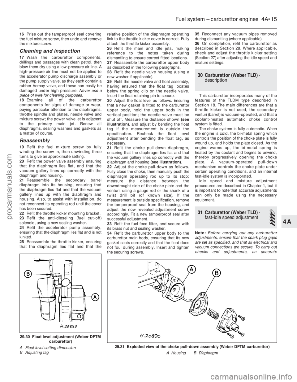
30 Adjust the float level as follows. Ensuring
that a new gasket is fitted to the carburettor
upper body, hold the upper body in the
vertical position; the needle valve must be
shut off. Measure the distance shown (see
illustration) , and adjust by bending the float
tag if the measurement is outside the
specification. Recheck the float level
adjustment after bending the float tag, as
necessary.
31 Refit the choke pull-down diaphragm,
ensuring that the diaphragm lies flat and that
the vacuum gallery lines up correctly with the
diaphragm and housing (see illustration).
32 Adjust the choke pull-down as follows.
Fully close the choke, then manually push the
diaphragm operating rod up to its stop;
measure the distance between the
downdraught side of the choke plate and the
venturi, using a gauge rod or the shank of a
twist drill bit (of known size). If the
measurement is outside specification, remove
the tamperproof seal from the housing, and
adjust the now revealed adjustment screw
accordingly. Fit a new tamperproof seal after
successful adjustment.
33 Refit the fuel feed filter, and secure with
its brass nut and sealing washer.
34 Refit the carburettor upper body to the
carburettor main body, ensuring that its new
gasket seats correctly and that the float does
not foul during assembly. Insert and tighten
the securing screws. 35
Reconnect any vacuum pipes removed
during dismantling (where applicable).
36 On completion, refit the carburettor as
described in Section 28. Where applicable,
check and adjust the throttle kicker setting
(Section 27) after adjusting the idle speed and
mixture settings.
30 Carburettor (Weber TLD) -
description
This carburettor incorporates many of the
features of the TLDM type described in
Section 18. The main differences are that a
throttle kicker is not used, the secondary
venturi (barrel) is vacuum-operated, and that a
coolant-heated automatic choke control
system is fitted. The choke system is fully automatic. When
the engine is cold, the bi-metal spring which
controls the position of the choke plate is fully
wound up, and holds the plate closed. As the
engine warms up, the bi-metal spring is
heated by the coolant and begins to unwind,
thereby progressively opening the choke
plate. A vacuum-operated pull-down
mechanism controls the choke plate under
certain operating conditions, and an internal
fast-idle system is incorporated. Idle speed and mixture adjustment
procedures are described in Chapter 1, but it
is important to note that accurate adjustments
can only be made using the necessary
equipment.
31 Carburettor (Weber TLD) -
fast-idle speed adjustment
4
Note: Before carrying out any carburettor
adjustments, ensure that the spark plug gaps
are set as specified, and that all electrical and
vacuum connections are secure. To carry out
checks and adjustments, an accurate
Fuel system – carburettor engines 4A•15
29.31 Exploded view of the choke pull-down assembly (Weber DFTM carbur\
ettor)
A Housing B Diaphragm
29.30 Float level adjustment (Weber DFTMcarburettor)
A Float level setting dimension
B Adjusting tag
4A
1595Ford Fiesta Remakeprocarmanuals.com
http://vnx.su
Page 121 of 296
tachometer and an exhaust gas analyser (CO
meter) will be required.
1Check that the idle speed and mixture
settings are as specified (as described in
Chapter 1). These must be correct before
checking/adjusting the fast-idle speed.
2 Switch the engine off, then remove the air
cleaner as described in Section 2.
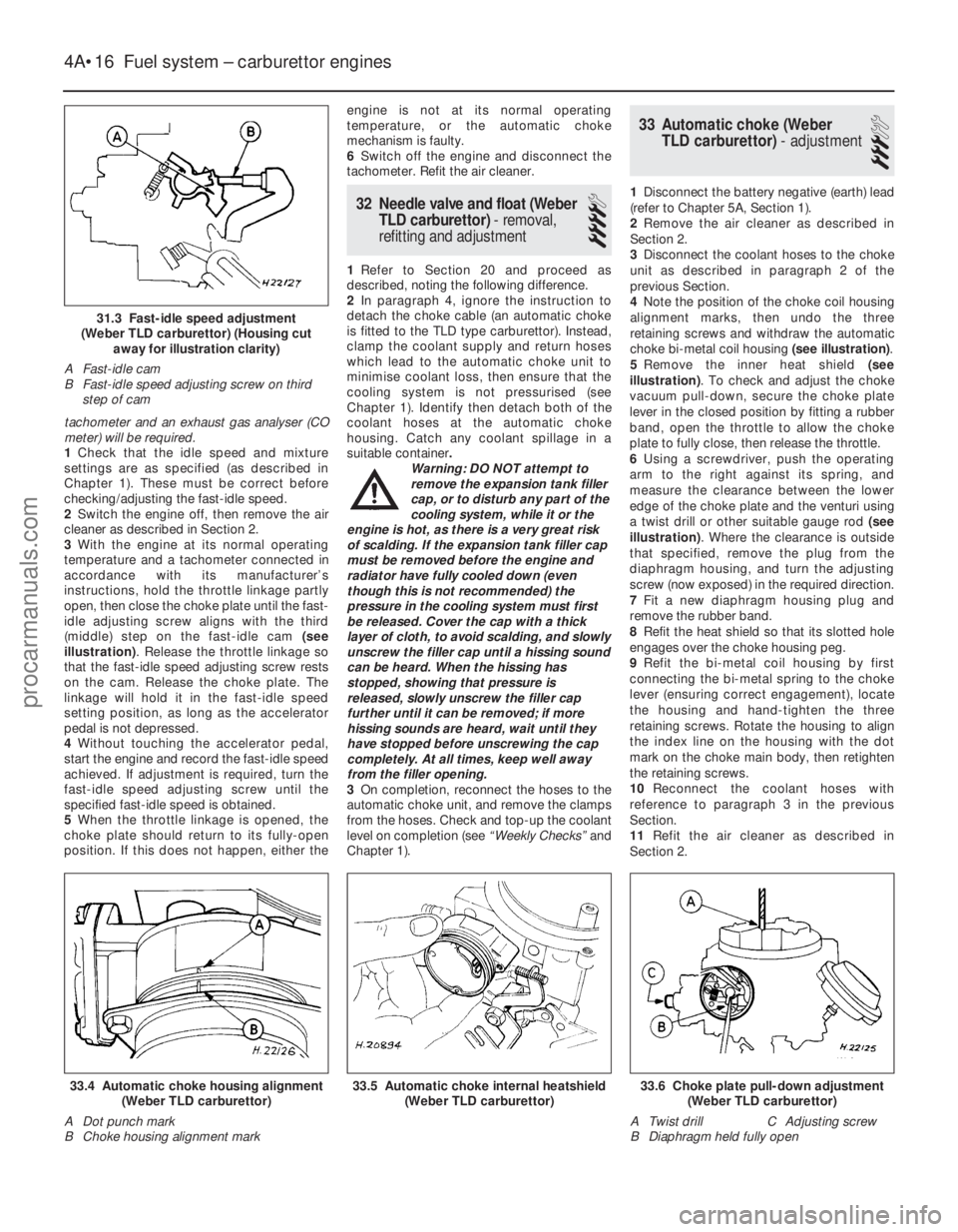
3 With the engine at its normal operating
temperature and a tachometer connected in
accordance with its manufacturer’s
instructions, hold the throttle linkage partly
open, then close the choke plate until the fast-
idle adjusting screw aligns with the third
(middle) step on the fast-idle cam (see
illustration) . Release the throttle linkage so
that the fast-idle speed adjusting screw rests
on the cam. Release the choke plate. The
linkage will hold it in the fast-idle speed
setting position, as long as the accelerator
pedal is not depressed.
4 Without touching the accelerator pedal,
start the engine and record the fast-idle speed
achieved. If adjustment is required, turn the
fast-idle speed adjusting screw until the
specified fast-idle speed is obtained.
5 When the throttle linkage is opened, the
choke plate should return to its fully-open
position. If this does not happen, either the engine is not at its normal operating
temperature, or the automatic choke
mechanism is faulty.
6
Switch off the engine and disconnect the
tachometer. Refit the air cleaner.
32 Needle valve and float (Weber
TLD carburettor) - removal,
refitting and adjustment
4
1 Refer to Section 20 and proceed as
described, noting the following difference.
2 In paragraph 4, ignore the instruction to
detach the choke cable (an automatic choke
is fitted to the TLD type carburettor). Instead,
clamp the coolant supply and return hoses
which lead to the automatic choke unit to
minimise coolant loss, then ensure that the
cooling system is not pressurised (see
Chapter 1). Identify then detach both of the
coolant hoses at the automatic choke
housing. Catch any coolant spillage in a
suitable container .
Warning: DO NOT attempt to
remove the expansion tank filler
cap, or to disturb any part of the
cooling system, while it or the
engine is hot, as there is a very great risk
of scalding. If the expansion tank filler cap
must be removed before the engine and
radiator have fully cooled down (even
though this is not recommended) the
pressure in the cooling system must first
be released. Cover the cap with a thick
layer of cloth, to avoid scalding, and slowly
unscrew the filler cap until a hissing sound
can be heard. When the hissing has
stopped, showing that pressure is
released, slowly unscrew the filler cap
further until it can be removed; if more
hissing sounds are heard, wait until they
have stopped before unscrewing the cap
completely. At all times, keep well away
from the filler opening.
3 On completion, reconnect the hoses to the
automatic choke unit, and remove the clamps
from the hoses. Check and top-up the coolant
level on completion (see “Weekly Checks”and
Chapter 1).
33 Automatic choke (Weber TLD carburettor) - adjustment
3
1Disconnect the battery negative (earth) lead
(refer to Chapter 5A, Section 1).
2 Remove the air cleaner as described in
Section 2.
3 Disconnect the coolant hoses to the choke
unit as described in paragraph 2 of the
previous Section.
4 Note the position of the choke coil housing
alignment marks, then undo the three
retaining screws and withdraw the automatic
choke bi-metal coil housing (see illustration).
5 Remove the inner heat shield (see
illustration) . To check and adjust the choke
vacuum pull-down, secure the choke plate
lever in the closed position by fitting a rubber
band, open the throttle to allow the choke
plate to fully close, then release the throttle.
6 Using a screwdriver, push the operating
arm to the right against its spring, and
measure the clearance between the lower
edge of the choke plate and the venturi using
a twist drill or other suitable gauge rod (see
illustration) . Where the clearance is outside
that specified, remove the plug from the
diaphragm housing, and turn the adjusting
screw (now exposed) in the required direction.
7 Fit a new diaphragm housing plug and
remove the rubber band.
8 Refit the heat shield so that its slotted hole
engages over the choke housing peg.
9 Refit the bi-metal coil housing by first
connecting the bi-metal spring to the choke
lever (ensuring correct engagement), locate
the housing and hand-tighten the three
retaining screws. Rotate the housing to align
the index line on the housing with the dot
mark on the choke main body, then retighten
the retaining screws.
10 Reconnect the coolant hoses with
reference to paragraph 3 in the previous
Section.
11 Refit the air cleaner as described in
Section 2.
4A•16 Fuel system – carburettor engines
33.6 Choke plate pull-down adjustment (Weber TLD carburettor)
A Twist drill C Adjusting screw
B Diaphragm held fully open33.5 Automatic choke internal heatshield (Weber TLD carburettor)33.4 Automatic choke housing alignment(Weber TLD carburettor)
A Dot punch mark
B Choke housing alignment mark
1595Ford Fiesta Remake
31.3 Fast-idle speed adjustment
(Weber TLD carburettor) (Housing cut away for illustration clarity)
A Fast-idle cam
B Fast-idle speed adjusting screw on third step of cam
procarmanuals.com
http://vnx.su
Page 122 of 296
34 Automatic choke (WeberTLD carburettor) - removal,
inspection and refitting
4
Note: Refer to the warning note in Section 1
before proceeding. A new carburettor upper
body gasket will be required when
reassembling. On completion, a tachometer
will be required to check the fast-idle speed
adjustment.
Removal
1 Disconnect the battery negative (earth) lead
(refer to Chapter 5A, Section 1).
2 Remove the air cleaner as described in
Section 2.
3 To prevent excess coolant loss, clamp the
coolant supply and return hoses to the
automatic choke unit, and ensure that the
cooling system is not pressurised (see
Chapter 1). Identify then detach both of the
coolant hoses at the automatic choke
housing. Catch any coolant spillage in a
suitable container.
Warning: DO NOT attempt to
remove the expansion tank filler
cap, or to disturb any part of the
cooling system, while it or the
engine is hot, as there is a very great risk
of scalding. If the expansion tank filler cap
must be removed before the engine and
radiator have fully cooled down (even
though this is not recommended) the
pressure in the cooling system must first
be released. Cover the cap with a thick
layer of cloth, to avoid scalding, and slowly
unscrew the filler cap until a hissing sound
can be heard. When the hissing has
stopped, showing that pressure is
released, slowly unscrew the filler cap
further until it can be removed; if more
hissing sounds are heard, wait until they
have stopped before unscrewing the cap
completely. At all times, keep well away
from the filler opening.
4 Detach the fuel pipe and the anti-dieseling
solenoid wiring connector. Any crimped type
hose clips must be replaced with a screw
clamp type clips during reassembly.
5 Unscrew and remove the retaining screws (two conventional, and four Torx type), then lift
the carburettor upper body clear and remove it.
6
Note the position of the choke housing
alignment marks, then undo the three retaining
screws and remove the choke bi-metal coil
unit. Remove the internal heat shield.
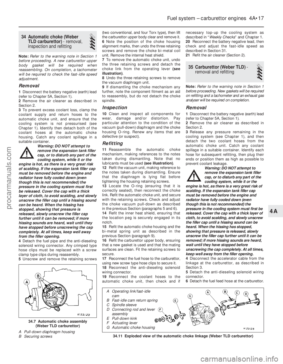
7 To remove the automatic choke unit, undo
the three retaining screws and detach the
choke link from the operating lever (see
illustration) .
8 Undo the three retaining screws to remove
the vacuum diaphragm unit.
9 If dismantling the choke mechanism any
further, note the component fitment as an aid
to reassembly, but do not detach the choke
spindle.
Inspection
10 Clean and inspect all components for
wear, damage and/or distortion. Pay
particular attention to the condition of the
vacuum (pull-down) diaphragm and the choke
housing O-ring. Renew any items that are
defective (or suspect).
Refitting
11 Reassemble the automatic choke
mechanism, making references to the notes
taken during dismantling. Note that no
lubricants must be used (see illustration).
12 Refit the vacuum unit, making reference to
the notes taken during dismantling. Ensure
that the diaphragm is lying flat before
tightening the housing retaining screws.
13 Locate the O-ring (ensuring that it is
correctly seated), then reconnect the choke
link. Refit the automatic choke unit, and secure
with the retaining screws. Check and adjust
the choke vacuum pull-down as described
in the previous Section (paragraphs 5 and 6).
14 Refit the inner heat shield, ensuring that
the location peg is securely engaged in its
notch.
15 Refit the automatic choke housing and the
bi-metal spring unit as described in the
previous Section (paragraph 9).
16 Refit the carburettor upper body, ensuring
that a new gasket is used and that the mating
surfaces are clean. Fit the retaining screws to
secure.
17 Reconnect the fuel hose to the carburettor,
using new screw type hose clips to secure it.
18 Reconnect the anti-dieseling solenoid
wiring connector.
19 Reconnect the coolant hoses to the
automatic choke unit, then check and if necessary top-up the cooling system as
described in “
Weekly Checks ” and Chapter 1.
20 Reconnect the battery negative lead, then
check and adjust the fast-idle speed as
described in Section 31.
21 Refit the air cleaner (Section 2).
35 Carburettor (Weber TLD) -
removal and refitting
4
Note: Refer to the warning note in Section 1
before proceeding. New gaskets will be required
on refitting and a tachometer and an exhaust gas
analyser will be required on completion.
Removal
1 Disconnect the battery negative (earth) lead
(refer to Chapter 5A, Section 1).
2 Remove the air cleaner as described in
Section 2.
3 Release any pressure remaining in the
cooling system (see Chapter 1), and then
detach the two coolant hoses from the
automatic choke unit. Catch any coolant
spillage in a suitable container. Identify each
hose for subsequent refitting, then plug their
ends or position them as high as possible to
prevent coolant leakage. Warning: DO NOT attempt to
remove the expansion tank filler
cap, or to disturb any part of the
cooling system, while it or the
engine is hot, as there is a very great risk of
scalding. If the expansion tank filler cap
must be removed before the engine and
radiator have fully cooled down (even
though this is not recommended) the
pressure in the cooling system must first be
released. Cover the cap with a thick layer of
cloth, to avoid scalding, and slowly unscrew
the filler cap until a hissing sound can be
heard. When the hissing has stopped,
showing that pressure is released, slowly
unscrew the filler cap further until it can be
removed; if more hissing sounds are heard,
wait until they have stopped before
unscrewing the cap completely. At all times,
keep well away from the filler opening.
4 Disconnect the accelerator cable from the
linkage at the carburettor, as described in
Section 3.
5 Detach the anti-dieseling solenoid wiring
connector.
6 Detach the fuel feed hose at the carburettor.
Fuel system – carburettor engines 4A•17
34.11 Exploded view of the automatic choke linkage (Weber TLD carburet\
tor)
34.7 Automatic choke assembly
(Weber TLD carburettor)
A Pull-down diaphragm housing
B Securing screws
4A
1595Ford Fiesta Remake
A Operating link/fast-idle cam
B Fast-idle cam return spring
C Spindle sleeve
D Connecting rod and lever assembly
E Pull-down kink
F Actuating lever
G Automatic choke housing
procarmanuals.com
http://vnx.su