1989 FORD FIESTA engine coolant
[x] Cancel search: engine coolantPage 140 of 296
Crankshaft position sensor
40Refer to Chapter 5B.
Coolant temperature sensor
41Refer to Chapter 3.
Inlet air temperature sensor
42Remove the air inlet components as
described in Section 4.
43 Releasing its clip, unplug the sensor’s
electrical connector, then unscrew the sensor
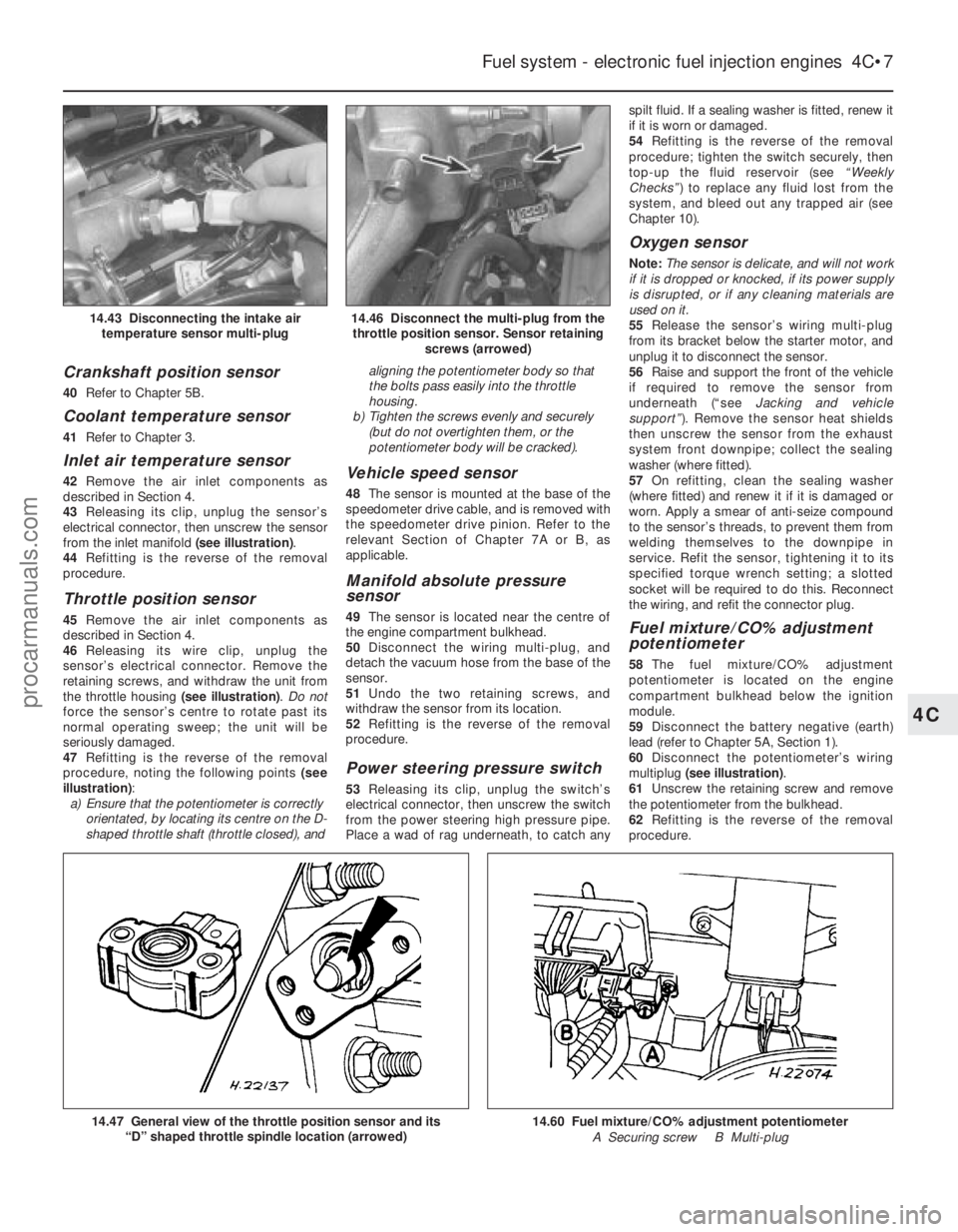
from the inlet manifold (see illustration).
44 Refitting is the reverse of the removal
procedure.
Throttle position sensor
45 Remove the air inlet components as
described in Section 4.
46 Releasing its wire clip, unplug the
sensor’s electrical connector. Remove the
retaining screws, and withdraw the unit from
the throttle housing (see illustration). Do not
force the sensor’s centre to rotate past its
normal operating sweep; the unit will be
seriously damaged.
47 Refitting is the reverse of the removal
procedure, noting the following points (see
illustration) :
a) Ensure that the potentiometer is correctly
orientated, by locating its centre on the D-
shaped throttle shaft (throttle closed), and aligning the potentiometer body so that
the bolts pass easily into the throttle
housing.
b) Tighten the screws evenly and securely
(but do not overtighten them, or the
potentiometer body will be cracked).
Vehicle speed sensor
48 The sensor is mounted at the base of the
speedometer drive cable, and is removed with
the speedometer drive pinion. Refer to the
relevant Section of Chapter 7A or B, as
applicable.
Manifold absolute pressure
sensor
49 The sensor is located near the centre of
the engine compartment bulkhead.
50 Disconnect the wiring multi-plug, and
detach the vacuum hose from the base of the
sensor.
51 Undo the two retaining screws, and
withdraw the sensor from its location.
52 Refitting is the reverse of the removal
procedure.
Power steering pressure switch
53 Releasing its clip, unplug the switch’s
electrical connector, then unscrew the switch
from the power steering high pressure pipe.
Place a wad of rag underneath, to catch any spilt fluid. If a sealing washer is fitted, renew it
if it is worn or damaged.
54
Refitting is the reverse of the removal
procedure; tighten the switch securely, then
top-up the fluid reservoir (see “Weekly
Checks” ) to replace any fluid lost from the
system, and bleed out any trapped air (see
Chapter 10).
Oxygen sensor
Note: The sensor is delicate, and will not work
if it is dropped or knocked, if its power supply
is disrupted, or if any cleaning materials are
used on it.
55 Release the sensor’s wiring multi-plug
from its bracket below the starter motor, and
unplug it to disconnect the sensor.
56 Raise and support the front of the vehicle
if required to remove the sensor from
underneath (“see Jacking and vehicle
support” ). Remove the sensor heat shields
then unscrew the sensor from the exhaust
system front downpipe; collect the sealing
washer (where fitted).
57 On refitting, clean the sealing washer
(where fitted) and renew it if it is damaged or
worn. Apply a smear of anti-seize compound
to the sensor’s threads, to prevent them from
welding themselves to the downpipe in
service. Refit the sensor, tightening it to its
specified torque wrench setting; a slotted
socket will be required to do this. Reconnect
the wiring, and refit the connector plug.
Fuel mixture/CO% adjustment
potentiometer
58 The fuel mixture/CO% adjustment
potentiometer is located on the engine
compartment bulkhead below the ignition
module.
59 Disconnect the battery negative (earth)
lead (refer to Chapter 5A, Section 1).
60 Disconnect the potentiometer’s wiring
multiplug (see illustration) .
61 Unscrew the retaining screw and remove
the potentiometer from the bulkhead.
62 Refitting is the reverse of the removal
procedure.
Fuel system - electronic fuel injection engines 4C•7
14.46 Disconnect the multi-plug from the throttle position sensor. Sensor retaining screws (arrowed)14.43 Disconnecting the intake airtemperature sensor multi-plug
14.60 Fuel mixture/CO% adjustment potentiometer
A Securing screw B Multi-plug14.47 General view of the throttle position sensor and its “D” shaped throttle spindle location (arrowed)
4C
1595Ford Fiesta Remakeprocarmanuals.com
http://vnx.su
Page 141 of 296
15 Inlet manifold-
removal and refitting
4
Note: Refer to the warning note in Section 1
before proceeding.
Removal
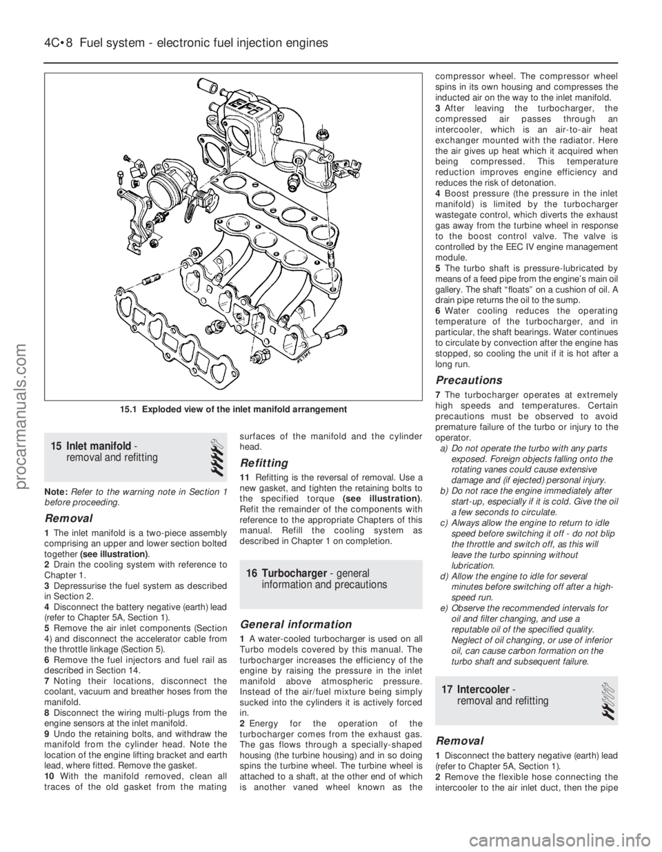
1 The inlet manifold is a two-piece assembly
comprising an upper and lower section bolted
together (see illustration) .
2 Drain the cooling system with reference to
Chapter 1.
3 Depressurise the fuel system as described
in Section 2.
4 Disconnect the battery negative (earth) lead
(refer to Chapter 5A, Section 1).
5 Remove the air inlet components (Section
4) and disconnect the accelerator cable from
the throttle linkage (Section 5).
6 Remove the fuel injectors and fuel rail as
described in Section 14.
7 Noting their locations, disconnect the
coolant, vacuum and breather hoses from the
manifold.
8 Disconnect the wiring multi-plugs from the
engine sensors at the inlet manifold.
9 Undo the retaining bolts, and withdraw the
manifold from the cylinder head. Note the
location of the engine lifting bracket and earth
lead, where fitted. Remove the gasket.
10 With the manifold removed, clean all
traces of the old gasket from the mating surfaces of the manifold and the cylinder
head.
Refitting
11
Refitting is the reversal of removal. Use a
new gasket, and tighten the retaining bolts to
the specified torque (see illustration).
Refit the remainder of the components with
reference to the appropriate Chapters of this
manual. Refill the cooling system as
described in Chapter 1 on completion.
16 Turbocharger - general
information and precautions
General information
1 A water-cooled turbocharger is used on all
Turbo models covered by this manual. The
turbocharger increases the efficiency of the
engine by raising the pressure in the inlet
manifold above atmospheric pressure.
Instead of the air/fuel mixture being simply
sucked into the cylinders it is actively forced
in.
2 Energy for the operation of the
turbocharger comes from the exhaust gas.
The gas flows through a specially-shaped
housing (the turbine housing) and in so doing
spins the turbine wheel. The turbine wheel is
attached to a shaft, at the other end of which
is another vaned wheel known as the compressor wheel. The compressor wheel
spins in its own housing and compresses the
inducted air on the way to the inlet manifold.
3
After leaving the turbocharger, the
compressed air passes through an
intercooler, which is an air-to-air heat
exchanger mounted with the radiator. Here
the air gives up heat which it acquired when
being compressed. This temperature
reduction improves engine efficiency and
reduces the risk of detonation.
4 Boost pressure (the pressure in the inlet
manifold) is limited by the turbocharger
wastegate control, which diverts the exhaust
gas away from the turbine wheel in response
to the boost control valve. The valve is
controlled by the EEC IV engine management
module.
5 The turbo shaft is pressure-lubricated by
means of a feed pipe from the engine’s main oil
gallery. The shaft “floats” on a cushion of oil. A
drain pipe returns the oil to the sump.
6 Water cooling reduces the operating
temperature of the turbocharger, and in
particular, the shaft bearings. Water continues
to circulate by convection after the engine has
stopped, so cooling the unit if it is hot after a
long run.
Precautions
7 The turbocharger operates at extremely
high speeds and temperatures. Certain
precautions must be observed to avoid
premature failure of the turbo or injury to the
operator. a) Do not operate the turbo with any parts
exposed. Foreign objects falling onto the
rotating vanes could cause extensive
damage and (if ejected) personal injury.
b) Do not race the engine immediately after
start-up, especially if it is cold. Give the oil
a few seconds to circulate.
c) Always allow the engine to return to idle
speed before switching it off - do not blip
the throttle and switch off, as this will
leave the turbo spinning without
lubrication.
d) Allow the engine to idle for several
minutes before switching off after a high-
speed run.
e) Observe the recommended intervals for oil and filter changing, and use a
reputable oil of the specified quality.
Neglect of oil changing, or use of inferior
oil, can cause carbon formation on the
turbo shaft and subsequent failure.
17 Intercooler -
removal and refitting
2
Removal
1 Disconnect the battery negative (earth) lead
(refer to Chapter 5A, Section 1).
2 Remove the flexible hose connecting the
intercooler to the air inlet duct, then the pipe
4C•8 Fuel system - electronic fuel injection engines
15.1 Exploded view of the inlet manifold arrangement
1595Ford Fiesta Remakeprocarmanuals.com
http://vnx.su
Page 142 of 296
and flexible hose connecting the turbocharger
to the intercooler (see illustration 4.12) . Use
adhesive tape to seal the turbocharger ports
against the entry of dirt.
3 Unbolt the horn nearest the intercooler.
4 Unbolt the radiator/intercooler assembly
from the bonnet closure panel and the body
crossmember.
5 Move the assembly as far as possible
towards the engine, and unbolt the intercooler
from the radiator; withdraw the intercooler.
Refitting
6 Refitting is the reverse of the removal
procedure, tightening all nuts and bolts to the
specified torque settings, and not forgetting
to unseal the turbocharger openings before
reconnecting the intercooler pipe and hose.
18 Turbocharger boost control valve - removal and refitting
2
Removal
1Disconnect the battery negative (earth) lead
(refer to Chapter 5A, Section 1).
2 Disconnect the control valve wiring at its
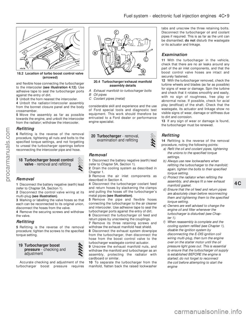
multi-plug (see illustration) .
3 Marking or labelling the valve hoses so that
each can be reconnected to its original union,
disconnect the hoses from the valve.
4 Remove the securing screws and withdraw
the valve.
Refitting
5 Refitting is the reverse of the removal
procedure; tighten the screws to the specified
torque setting.
19 Turbocharger boost pressure - checking and
adjustment
5
Accurate checking and adjustment of the
turbocharger boost pressure requires considerable skill and experience and the use
of Ford special tools and diagnostic test
equipment. This work should therefore be
entrusted to a Ford dealer or performance
engine specialist.
20 Turbocharger
- removal,
examination and refitting
3
Removal
1 Disconnect the battery negative (earth) lead
(refer to Chapter 5A, Section 1).
2 Drain the cooling system as described in
Chapter 1.
3 Remove the air inlet components as
described in Section 4.
4 Disconnect the turbocharger coolant feed
and return hoses by slackening the clamps
and pulling the hoses off the turbocharger’s
metal pipes (see illustration) .
5 Remove the pipe and flexible hoses
connecting the turbocharger to the air cleaner
and intercooler. Use adhesive tape to seal the
turbocharger ports against the entry of dirt.
6 Disconnect the turbocharger oil feed and
return pipes by unscrewing the couplings.
7 Remove its three retaining screws and
withdraw the exhaust manifold heat shield.
8 Disconnect the exhaust system downpipe
from the turbocharger, then disconnect the
hose from the boost control valve to the
turbocharger wastegate control actuator.
9 Unscrew the exhaust manifold nuts, and
withdraw the manifold and turbocharger as an
assembly, protecting the radiator with
cardboard or similar.
10 To separate the turbocharger from the
manifold, flatten back the raised lockwasher tabs and unscrew the three retaining bolts.
Disconnect the turbocharger oil and coolant
pipes if required. This is as far as the unit can
be dismantled;
do notdisturb the wastegate
or its actuator and linkage.
Examination
11 With the turbocharger in the vehicle,
check that there are no air leaks around any
part of the air inlet components, and that the
boost control valve hoses are intact and
securely fastened.
12 With the turbocharger removed, check the
turbine wheels and blades (as far as possible)
for signs of wear or damage. Spin the turbine
and check that it rotates smoothly and easily,
with no sign of roughness, free play or
abnormal noise. If possible, check for axial
play (endfloat) of the shaft. Check that the
wastegate, its actuator and linkage show no
visible signs of wear, damage or stiffness due
to dirt and corrosion.
13 If any sign of wear or damage is found,
the turbocharger must be renewed.
Refitting
14 Refitting is the reverse of the removal
procedure, noting the following points: a) Refit the oil and coolant pipes, tightening
the unions to the specified torque
settings.
b) Always use new lockwashers when
refitting the turbocharger to the manifold;
again, tighten the bolts to their specified
torque setting.
c) Protect the radiator when refitting the
assembly, and always fit a new exhaust
manifold gasket.
d) Ensure that the oil feed and return pipes
are absolutely clean before reconnecting
them and tightening them to the specified
torque setting.
e) Owners are well advised to change the engine oil and filter whenever the
turbocharger is disturbed (see Chap-
ter 1).
f) When reassembly is complete and the
cooling system refilled (see Chapter 1),
disable the ignition system by
disconnecting the E-DIS ignition coil
wiring multi-plug, then turn the engine
over on the starter motor until the oil
pressure light goes out. This is essential
to ensure that the turbocharger oil supply
is established BEFORE the engine is
started; do not forget to reconnect
the coil before attempting to start the
engine
Fuel system - electronic fuel injection engines 4C•9
20.4 Turbocharger/exhaust manifold assembly details
A Exhaust manifold-to-turbocharger bolts
B Oil pipes
C Coolant pipes (metal)
4C
1595Ford Fiesta Remake
18.2 Location of turbo boost control valve (arrowed)
procarmanuals.com
http://vnx.su
Page 145 of 296
1 General information andprecautions
General information
The fuel system consists of a fuel tank
(mounted under the body, beneath the rear
seats), fuel hoses, an electric fuel pump
mounted in the fuel tank, and a sequential
electronic fuel injection system.
The electric fuel pump supplies fuel under
pressure to the fuel rail, which distributes fuel
evenly to all injectors. A pressure regulator
controls the system pressure in relation to
inlet tract depression. From the fuel rail, fuel is
injected into the inlet ports, just above the
inlet valves, by four fuel injectors. The system
also includes features such as the flushing of
fresh (ie, cold) fuel around each injector on
start-up, thus improving hot starts. The amount of fuel supplied by the injectors
is precisely controlled by the EEC IV engine
management module. The module uses the
signals derived from the crankshaft position
sensor and the camshaft position sensor, to
trigger each injector separately in cylinder
firing order (sequential injection), with benefits
in terms of better fuel economy and lower
exhaust emissions. The EEC IV module is the heart of the entire
engine management system, controlling the
fuel injection, ignition and emissions control
systems. The module receives information
from various sensors which is then computed
and compared with pre-set values stored in
it’s memory, to determine the required period
of injection. Information on crankshaft position and
engine speed is generated by a crankshaft
position sensor. The inductive head of the
sensor runs just above the engine flywheel
and scans a series of 36 protrusions on the
flywheel periphery. As the crankshaft rotates,
the sensor transmits a pulse to the system’s
ignition module every time a protrusion
passes it. There is one missing protrusion in
the flywheel periphery at a point
corresponding to 90° BTDC. The ignition
module recognises the absence of a pulse
from the crankshaft position sensor at this
point to establish a reference mark for
crankshaft position. Similarly, the time interval
between absent pulses is used to determine
engine speed. This information is then fed to
the EEC IV module for further processing. The camshaft position sensor is located in
the cylinder head so that it registers with a
lobe on the camshaft. The camshaft position
sensor functions in the same way as the
crankshaft position sensor, producing a series
of pulses; this gives the EEC IV module a
reference point, to enable it to determine the
firing order, and operate the injectors in the
appropriate sequence. The mass air flow sensor is based on a “hot-
wire” system, sending the EEC IV module a constantly-varying (analogue) voltage signal
corresponding to the mass of air passing into
the engine. Since air mass varies with
temperature (cold air being denser than warm),
measuring air mass provides the module with
a very accurate means of determining the
correct amount of fuel required to achieve the
ideal air/fuel mixture ratio.
Engine temperature information is supplied by
the coolant temperature sensor. This
component is an NTC (Negative Temperature
Coefficient) thermistor - that is, a semi-
conductor whose electrical resistance
decreases as its temperature increases. It
provides the EEC IV module with a constantly-
varying (analogue) voltage signal, corresponding
to the temperature of the engine coolant. This is
used to refine the calculations made by the
module, when determining the correct amount
of fuel required to achieve the ideal air/fuel
mixture ratio. Inlet air temperature information is supplied
by the inlet air temperature sensor. This
component is also an NTC thermistor - see
the previous paragraph - providing the
module with a signal corresponding to the
temperature of air passing into the engine.
This is used to refine the calculations made by
the module, when determining the correct
amount of fuel required to achieve the ideal
air/fuel mixture ratio. A throttle position sensor is mounted on the
end of the throttle valve spindle, to provide
the EEC IV module with a constantly-varying
(analogue) voltage signal corresponding to the
throttle opening. This allows the module to
register the driver’s input when determining
the amount of fuel required by the engine.
Road speed is monitored by the vehicle
speed sensor. This component is a Hall-effect
generator, mounted on the transmission’s
speedometer drive. It supplies the module
with a series of pulses corresponding to the
vehicle’s road speed, enabling the module to
control features such as the fuel shut-off on
overrun.
Where power steering is fitted, a pressure-
operated switch is screwed into the power
steering system’s high-pressure pipe. The
switch sends a signal to the EEC IV module to
reduce engine speed should the power
steering fluid pressure become excessively
high.
The oxygen sensor in the exhaust system
provides the module with constant feedback -
“closed-loop” control - which enables it to
adjust the mixture to provide the best possible
conditions for the catalytic converter to
operate. The air inlet side of the system consists of
an air cleaner housing, the mass air flow
sensor, an inlet hose and duct, and a throttle
housing. The throttle valve inside the throttle housing
is controlled by the driver, through the
accelerator pedal. As the valve opens, the
amount of air that can pass through the
system increases. As the throttle valve opens further, the mass air flow sensor signal alters,
and the EEC IV module opens each injector
for a longer duration, to increase the amount
of fuel delivered to the inlet ports.
Both the idle speed and mixture are under
the control of the EEC IV module, and cannot
be adjusted. Not only can they not be
adjusted, they cannot even be checked,
except with the use of special Ford diagnostic
equipment.
Precautions
Warning: Petrol is extremely
flammable - great care must be
taken when working on any part
of the fuel system. Do not
smoke or allow any naked flames or
uncovered light bulbs near the work area.
Note that gas powered domestic
appliances with pilot flames, such as
heaters, boilers and tumble dryers, also
present a fire hazard - bear this in mind if
you are working in an area where such
appliances are present. Always keep a
suitable fire extinguisher close to the work
area and familiarise yourself with its
operation before starting work. Wear eye
protection when working on fuel systems
and wash off any fuel spilt on bare skin
immediately with soap and water. Note
that fuel vapour is just as dangerous as
liquid fuel; a vessel that has just been
emptied of liquid fuel will still contain
vapour and can be potentially explosive.
Petrol is a highly dangerous and volatile
liquid, and the precautions necessary
when handling it cannot be overstressed. Many of the operations described in this
Chapter involve the disconnection of fuel
lines, which may cause an amount of fuel
spillage. Before commencing work, refer
to the above Warning and the information
in “Safety first” at the beginning of this
manual. When working with fuel system
components, pay particular attention to
cleanliness - dirt entering the fuel system
may cause blockages which will lead to
poor running.
Note: Residual pressure will remain in the fuel
lines long after the vehicle was last used,
when disconnecting any fuel line, it will be
necessary to depressurise the fuel system as
described in Section 2 .
2 Fuel system-
depressurisation
1
Refer to Part B, Section 2.
3 Fuel lines and fittings -
general information
Refer to Part B, Section 3.
4D•2 Fuel system - sequential electronic fuel injection engines
1595Ford Fiesta Remakeprocarmanuals.com
http://vnx.su
Page 149 of 296
25Refitting is the reverse of the removal
procedure, noting the following points: a) Renew the regulator sealing O-ring
whenever the regulator is disturbed.
Lubricate the new O-ring with clean
engine oil on installation.
b) Locate the regulator carefully in the fuel
rail recess, and tighten the bolts securely.
c) On completion, switch the ignition on and off five times, to activate the fuel pump
and pressurise the system, without
cranking the engine. Check for signs of
fuel leaks around all disturbed unions and
joints before attempting to start the
engine.
Idle speed control valve
26 Disconnect the battery negative (earth)
lead (refer to Chapter 5A, Section 1).
27 Disconnect the valve’s wiring multi-plug
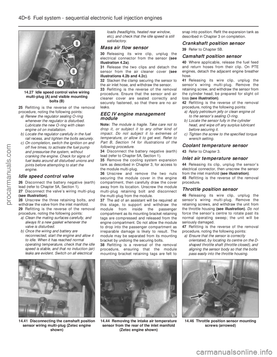
(see illustration) .
28 Unscrew the three retaining bolts, and
withdraw the valve from the inlet manifold.
29 Refitting is the reverse of the removal
procedure, noting the following points: a) Clean the mating surfaces carefully, and
always fit a new gasket whenever the
valve is disturbed.
b) Once the wiring and battery are
reconnected, start the engine and allow it
to idle. When it has reached normal
operating temperature, check that the idle
speed is stable, and that no induction (air)
leaks are evident. Switch on all electrical loads (headlights, heated rear window,
etc), and check that the idle speed is still
satisfactory.
Mass air flow sensor
30
Releasing its wire clip, unplug the
electrical connector from the sensor (see
illustration 4.2a) .
31 Release the two clips and detach the
sensor from the air cleaner cover (see
illustrations 4.2b and 4.2c) .
32 Slacken the clamp securing the sensor to
the air inlet hose, and withdraw the sensor.
33 Refitting is the reverse of the removal
procedure. Ensure that the sensor and air
cleaner cover are seated correctly and
securely fastened, so that there are no air
leaks.
EEC IV engine management
module
Note: The module is fragile. Take care not to
drop it, or subject it to any other kind of
impact. Do not subject it to extremes of
temperature, or allow it to get wet. Refer to
Part B, Section 14 for illustrations of the
following procedure.
34 Disconnect the battery negative (earth)
lead (refer to Chapter 5A, Section 1).
35 Remove the cooling system expansion
tank as described in Chapter 3, for access to
the module multi-plug.
36 Unscrew and remove the two nuts
securing the module cover in the engine
compartment, then carefully draw the cover
away from its location. Unscrew the module
multi-plug retaining bolt and disconnect
the multi-plug from the module.
37 The aid of an assistant will be required at
this stage, to support and withdraw the
module from inside the passenger
compartment as its mounting bracket retaining
tags are compressed and released from the
engine compartment. Do not allow the module
to drop into the passenger compartment as
irreparable damage is likely to result. The
module may be separated from its mounting
bracket by undoing the securing bolts.
38 Refitting is a reversal of the removal
procedure, ensuring that the module
mounting bracket retaining tags are felt to snap into position. Refit the expansion tank as
described in Chapter 3 on completion.
Crankshaft position sensor
39
Refer to Chapter 5B.
Camshaft position sensor
40Where applicable, release the fuel feed
and return hoses from their clip. On PTE
engines, detach the adjacent engine breather
hose.
41 Releasing its wire clip, unplug the
sensor’s wiring multi-plug. Remove the
retaining screw, and withdraw the sensor from
the cylinder head; be prepared for slight oil
loss (see illustration) .
42 Refitting is the reverse of the removal
procedure, noting the following points: a) Apply petroleum jelly or clean engine oil
to the sensor’s sealing O-ring.
b) Locate the sensor fully in the cylinder
head, and wipe off any surplus lubricant
before securing it.
c) Tighten the screw to the specified torque wrench setting.
Coolant temperature sensor
43 Refer to Chapter 3.
Inlet air temperature sensor
44Releasing its clip, unplug the sensor’s
electrical connector, then unscrew the sensor
from the inlet manifold (see illustration).
45 Refitting is the reverse of the removal
procedure.
Throttle position sensor
46 Releasing its wire clip, unplug the
sensor’s wiring multi-plug. Remove the
retaining screws, and withdraw the unit from
the throttle housing (see illustration). Do not
force the sensor’s centre to rotate past its
normal operating sweep; the unit will be
seriously damaged.
47 Refitting is the reverse of the removal
procedure, noting the following points: a) Ensure that the sensor is correctly orientated, by locating its centre on the D-
shaped throttle shaft (throttle closed), and
aligning the sensor body so that the bolts
pass easily into the throttle housing.
4D•6 Fuel system - sequential electronic fuel injection engines
14.46 Throttle position sensor mounting screws (arrowed)14.44 Removing the intake air temperaturesensor from the rear of the inlet manifold
(Zetec engine shown)14.41 Disconnecting the camshaft positionsensor wiring multi-plug (Zetec engine
shown)
14.27 Idle speed control valve wiringmulti-plug (A) and visible mounting bolts (B)
1595Ford Fiesta Remakeprocarmanuals.com
http://vnx.su
Page 150 of 296
b)Tighten the screws evenly and securely
(but do not overtighten them, or the
potentiometer body will be cracked).
Vehicle speed sensor
48 The sensor is mounted at the base of the
speedometer drive cable, and is removed with
the speedometer drive pinion. Refer to the
relevant Section of Chapter 7A or B, as
applicable.
Power steering pressure switch
49 Releasing its clip, unplug the switch’s
electrical connector, then unscrew the switch
from the power steering high pressure pipe.
Place a wad of rag underneath, to catch any
spilt fluid. If a sealing washer is fitted, renew it
if it is worn or damaged.
50 Refitting is the reverse of the removal
procedure; tighten the switch securely, then
top-up the fluid reservoir (see “Weekly
Checks”) to replace any fluid lost from the
system, and bleed out any trapped air (see
Chapter 10).
Oxygen sensor
Note: The sensor is delicate, and will not work
if it is dropped or knocked, if its power supply
is disrupted, or if any cleaning materials are
used on it.
51 Raise and support the front of the vehicle
if required to remove the sensor from
underneath (“see Jacking and vehicle
support” ).
52 Release the sensor’s wiring multi-plug
from its support bracket, and unplug it to
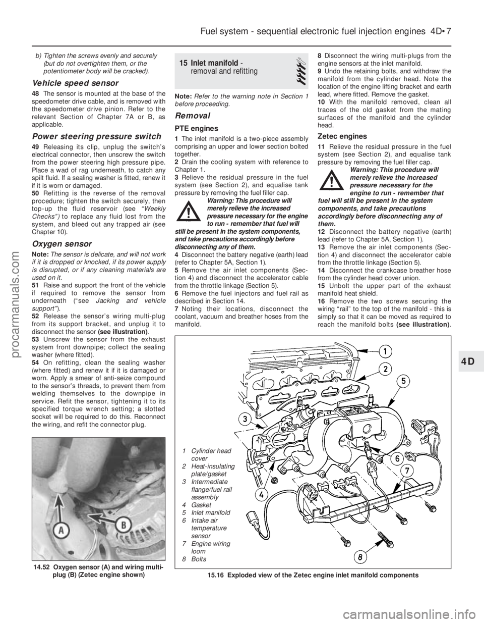
disconnect the sensor (see illustration).
53 Unscrew the sensor from the exhaust
system front downpipe; collect the sealing
washer (where fitted).
54 On refitting, clean the sealing washer
(where fitted) and renew it if it is damaged or
worn. Apply a smear of anti-seize compound
to the sensor’s threads, to prevent them from
welding themselves to the downpipe in
service. Refit the sensor, tightening it to its
specified torque wrench setting; a slotted
socket will be required to do this. Reconnect
the wiring, and refit the connector plug.
15 Inlet manifold -
removal and refitting
4
Note: Refer to the warning note in Section 1
before proceeding.
Removal
PTE engines
1 The inlet manifold is a two-piece assembly
comprising an upper and lower section bolted
together.
2 Drain the cooling system with reference to
Chapter 1.
3 Relieve the residual pressure in the fuel
system (see Section 2), and equalise tank
pressure by removing the fuel filler cap. Warning: This procedure will
merely relieve the increased
pressure necessary for the engine
to run - remember that fuel will
still be present in the system components,
and take precautions accordingly before
disconnecting any of them.
4 Disconnect the battery negative (earth) lead
(refer to Chapter 5A, Section 1).
5 Remove the air inlet components (Sec-
tion 4) and disconnect the accelerator cable
from the throttle linkage (Section 5).
6 Remove the fuel injectors and fuel rail as
described in Section 14.
7 Noting their locations, disconnect the
coolant, vacuum and breather hoses from the
manifold. 8
Disconnect the wiring multi-plugs from the
engine sensors at the inlet manifold.
9 Undo the retaining bolts, and withdraw the
manifold from the cylinder head. Note the
location of the engine lifting bracket and earth
lead, where fitted. Remove the gasket.
10 With the manifold removed, clean all
traces of the old gasket from the mating
surfaces of the manifold and the cylinder
head.Zetec engines
11 Relieve the residual pressure in the fuel
system (see Section 2), and equalise tank
pressure by removing the fuel filler cap. Warning: This procedure will
merely relieve the increased
pressure necessary for the
engine to run - remember that
fuel will still be present in the system
components, and take precautions
accordingly before disconnecting any of
them.
12 Disconnect the battery negative (earth)
lead (refer to Chapter 5A, Section 1).
13 Remove the air inlet components (Sec-
tion 4) and disconnect the accelerator cable
from the throttle linkage (Section 5).
14 Disconnect the crankcase breather hose
from the cylinder head cover union.
15 Unbolt the upper part of the exhaust
manifold heat shield.
16 Remove the two screws securing the
wiring “rail” to the top of the manifold - this is
simply so that it can be moved as required to
reach the manifold bolts (see illustration).
Fuel system - sequential electronic fuel injection engines 4D•7
14.52 Oxygen sensor (A) and wiring multi-
plug (B) (Zetec engine shown)15.16 Exploded view of the Zetec engine inlet manifold components
4D
1595Ford Fiesta Remake
1 Cylinder head
cover
2 Heat-insulating plate/gasket
3 Intermediate flange/fuel rail
assembly
4 Gasket
5 Inlet manifold
6 Intake air temperature
sensor
7 Engine wiring
loom
8 Boltsprocarmanuals.com
http://vnx.su
Page 151 of 296

Unplug the electrical connectors at the
camshaft position sensor and the coolant
temperature sensor, then unclip the wiring
from the ignition coil bracket, and secure it to
the manifold.
17Remove the three screws securing the
wiring “rail” to the rear of the manifold.
Releasing its wire clip, unplug the large
electrical connector (next to the fuel pressure
regulator) to disconnect the wiring of the
manifold components from the engine wiring
loom.
18 Marking or labelling them as they are
unplugged, disconnect the vacuum hoses at
the manifold and throttle housing.
19 Undo the fuel feed and return lines
connecting the engine to the chassis. Plug or
cap all open fittings. 20
Unbolt the earth lead from the cylinder
head rear support plate/engine lifting eye,
then unscrew the bolt securing the support
plate/lifting eye.
21 Unscrew the nuts and bolts securing the
manifold to the cylinder head, and withdraw it.
Take care not to damage vulnerable
components as the manifold assembly is
manoeuvred out of the engine compartment.
22 With the manifold removed, clean all
traces of the old gasket from the mating
surfaces of the manifold and the cylinder head.
Refitting
All engines
23 Refitting is the reverse of the removal
procedure, noting the following points: a) Fit a new gasket, then locate the manifold on the head and install the nuts and bolts.
b) Tighten the nuts/bolts in three or four
equal steps to the specified torque,
working from the centre outwards, to
avoid warping the manifold.
c) Refit the remaining parts in the reverse order of removal - tighten all fasteners to
the torque wrench settings specified
(where given).
d) Where drained, refill the cooling system
as described in Chapter 1.
e) Before starting the engine, check the accelerator cable for correct adjustment
and the throttle linkage for smooth
operation (Section 5).
f) When the engine is fully warmed-up,
check for signs of fuel, inlet and/or
vacuum leaks.
4D•8 Fuel system - sequential electronic fuel injection engines
1595Ford Fiesta Remakeprocarmanuals.com
http://vnx.su
Page 155 of 296
2The exhaust manifold is secured the
cylinder head by studs and nuts, and is
similarly attached to the exhaust downpipe. A
shroud/heat shield is bolted to the manifold,
to direct exhaust-heated air into the air inlet
system when the engine is cold. Access to the
exhaust manifold retaining nuts is gained by
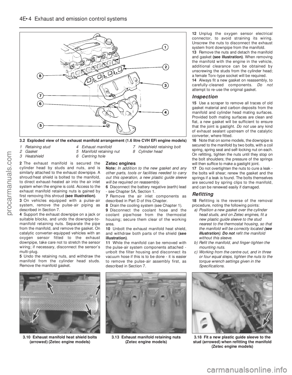
first removing this shroud (see illustration).
3 On vehicles equipped with a pulse-air
system, remove the pulse-air piping as
described in Section 7.
4 Support the exhaust downpipe on a jack or
suitable blocks, and undo the downpipe-to-
manifold retaining nuts. Separate the pipe
from the manifold, and remove the gasket. On
catalytic converter-equipped vehicles with an
oxygen sensor fitted to the exhaust
downpipe, take care not to stretch the sensor
wiring; if necessary, disconnect the sensor’s
multi-plug.
5 Undo the retaining nuts, and withdraw the
manifold from the cylinder head studs.
Remove the manifold gasket.Zetec enginesNote: In addition to the new gasket and any
other parts, tools or facilities needed to carry
out this operation, a new plastic guide sleeve
will be required on reassembly.
6 Disconnect the battery negative (earth) lead
- see Chapter 5A, Section 1.
7 Remove the air inlet components as
described in Part D of this Chapter.
8 Drain the cooling system (see Chapter 1).
9 Disconnect the coolant hose and the
coolant pipe/hose from the thermostat
housing; secure them clear of the working
area.
10 Unbolt the exhaust manifold heat shield,
and withdraw both parts of the shield (see
illustration) .
11 While the manifold can be removed with
the pulse-air system components attached -
unbolt the filter housing and disconnect its
vacuum hose if this is to be done - it is easier
to remove the pulse-air assembly first, as
described in Section 7. 12
Unplug the oxygen sensor electrical
connector, to avoid straining its wiring.
Unscrew the nuts to disconnect the exhaust
system front downpipe from the manifold.
13 Remove the nuts and detach the manifold
and gasket (see illustration) . When removing
the manifold with the engine in the vehicle,
additional clearance can be obtained by
unscrewing the studs from the cylinder head;
a female Torx-type socket will be required.
14 Always fit a new gasket on reassembly, to
carefully-cleaned components. Do not
attempt to re-use the original gasket.
Inspection
15 Use a scraper to remove all traces of old
gasket material and carbon deposits from the
manifold and cylinder head mating surfaces.
Provided both mating surfaces are clean and
flat, a new gasket will be sufficient to ensure
that the joint is gastight. Do not use any kind
of exhaust sealant upstream of the catalytic
converter, where fitted.
16 Note that on some models, the downpipe is
secured to the manifold by two bolts, with a coil
spring, spring seat and self-locking nut on each.
On refitting, tighten the nuts until they stop on
the bolt shoulders; the pressure of the springs
will then suffice to make a gastight joint.
17 Do not overtighten the nuts to cure a leak -
the bolts will shear; renew the gasket and the
springs if a leak is found. The bolts themselves
are secured by spring clips to the manifold,
and can be renewed easily if damaged.
Refitting
18 Refitting is the reverse of the removal
procedure, noting the following points: a) Position a new gasket over the cylinder head studs, and on Zetec engines, fit a
new plastic guide sleeve to the stud
nearest to the thermostat housing, so that
the manifold will be correctly located (see
illustration) . Do notrefit the manifold
without this sleeve.
b) Refit the manifold, and finger-tighten the
mounting nuts.
c) Working from the centre out, and in three or four equal steps, tighten the nuts to the
torque wrench settings given in the
Specifications.
4E•4 Exhaust and emission control systems
3.18 Fit a new plastic guide sleeve to the
stud (arrowed) when refitting the manifold
(Zetec engine models)3.13 Exhaust manifold retaining nuts(Zetec engine models)3.10 Exhaust manifold heat shield bolts(arrowed) (Zetec engine models)
3.2 Exploded view of the exhaust manifold arrangement (1.6 litre CVH E\
Fi engine models)
1 Retaining stud
2 Gasket
3 Heatshield 4 Exhaust manifold
5 Manifold retaining nut
6 Centring hole 7 Heatshield retaining bolt
8 Cylinder head
1595Ford Fiesta Remakeprocarmanuals.com
http://vnx.su