1989 FORD FIESTA engine coolant
[x] Cancel search: engine coolantPage 83 of 296
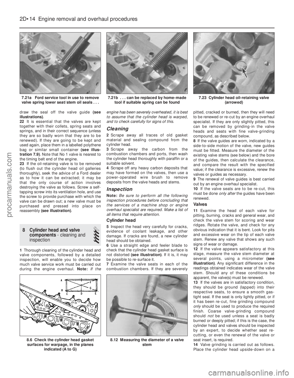
draw the seal off the valve guide (see
illustrations) .
22 It is essential that the valves are kept
together with their collets, spring seats and
springs, and in their correct sequence (unless
they are so badly worn that they are to be
renewed). If they are going to be kept and
used again, place them in a labelled polythene
bag or similar small container (see illus-
tration 7.9) . Note that No 1 valve is nearest to
the timing belt end of the engine.
23 If the oil-retaining valve is to be removed
(to flush out the cylinder head oil galleries
thoroughly), seek the advice of a Ford dealer
as to how it can be extracted; it may be
that the only course of action involves
destroying the valve as follows. Screw a self-
tapping screw into its ventilation hole, and use
the screw to provide purchase with which the
valve can be drawn out; a new valve must be
purchased and pressed into place on
reassembly (see illustration) .
8 Cylinder head and valve
components - cleaning and
inspection
4
1 Thorough cleaning of the cylinder head and
valve components, followed by a detailed
inspection, will enable you to decide how
much valve service work must be carried out
during the engine overhaul. Note:If the engine has been severely overheated, it is best
to assume that the cylinder head is warped,
and to check carefully for signs of this.
Cleaning
2
Scrape away all traces of old gasket
material and sealing compound from the
cylinder head.
3 Scrape away the carbon from the
combustion chambers and ports, then wash
the cylinder head thoroughly with paraffin or a
suitable solvent.
4 Scrape off any heavy carbon deposits that
may have formed on the valves, then use a
power-operated wire brush to remove
deposits from the valve heads and stems.
Inspection
Note: Be sure to perform all the following
inspection procedures before concluding that
the services of a machine shop or engine
overhaul specialist are required. Make a list of
all items that require attention.
Cylinder head
5 Inspect the head very carefully for cracks,
evidence of coolant leakage, and other
damage. If cracks are found, a new cylinder
head should be obtained.
6 Use a straight edge and feeler blade to
check that the cylinder head gasket surface is
not distorted (see illustration) . If it is, it may
be possible to re-surface it.
7 Examine the valve seats in each of the
combustion chambers. If they are severely pitted, cracked or burned, then they will need
to be renewed or re-cut by an engine overhaul
specialist. If they are only slightly pitted, this
can be removed by grinding-in the valve
heads and seats with fine valve-grinding
compound, as described below.
8
If the valve guides are worn, indicated by a
side-to-side motion of the valve, new guides
must be fitted. Measure the diameter of the
existing valve stems (see below) and the bore
of the guides, then calculate the clearance,
and compare the result with the specified
value; if the clearance is excessive, renew the
valves or guides as necessary.
9 The renewal of valve guides is best carried
out by an engine overhaul specialist.
10 If the valve seats are to be re-cut, this
must be done only afterthe guides have been
renewed.
Valves
11 Examine the head of each valve for
pitting, burning, cracks and general wear, and
check the valve stem for scoring and wear
ridges. Rotate the valve, and check for any
obvious indication that it is bent. Look for pits
and excessive wear on the tip of each valve
stem. Renew any valve that shows any such
signs of wear or damage.
12 If the valve appears satisfactory at this
stage, measure the valve stem diameter at
several points, using a micrometer (see
illustration) . Any significant difference in the
readings obtained indicates wear of the valve
stem. Should any of these conditions be
apparent, the valve(s) must be renewed.
13 If the valves are in satisfactory condition,
they should be ground (lapped) into their
respective seats, to ensure a smooth gas-
tight seal. If the seat is only lightly pitted, or if
it has been re-cut, fine grinding compound
only should be used to produce the required
finish. Coarse valve-grinding compound
should notbe used unless a seat is badly
burned or deeply pitted; if this is the case, the
cylinder head and valves should be inspected
by an expert, to decide whether seat re-
cutting, or even the renewal of the valve or
seat insert, is required.
14 Valve grinding is carried out as follows.
Place the cylinder head upside-down on a
2D•14 Engine removal and overhaul procedures
8.12 Measuring the diameter of a valve
stem8.6 Check the cylinder head gasketsurfaces for warpage, in the planes
indicated (A to G)
7.23 Cylinder head oil-retaining valve (arrowed)7.21b . . . can be replaced by home-madetool if suitable spring can be found7.21a Ford service tool in use to removevalve spring lower seat/stem oil seals . . .
1595Ford Fiesta Remakeprocarmanuals.com
http://vnx.su
Page 87 of 296
12After removal, reassemble the big-end
bearing caps and shells on their respective
connecting rods, and refit the bolts finger-
tight. Leaving the old shells in place until
reassembly will help prevent the bearing
recesses from being accidentally nicked or
gouged. New shells should be used on
reassembly.
Inspection
13 Before the inspection process can begin,
the piston/connecting rod assemblies must
be cleaned, and the original piston rings
removed from the pistons.
14 Carefully expand the old rings over the top
of the pistons. The use of two or three old feeler
blades will be helpful in preventing the rings
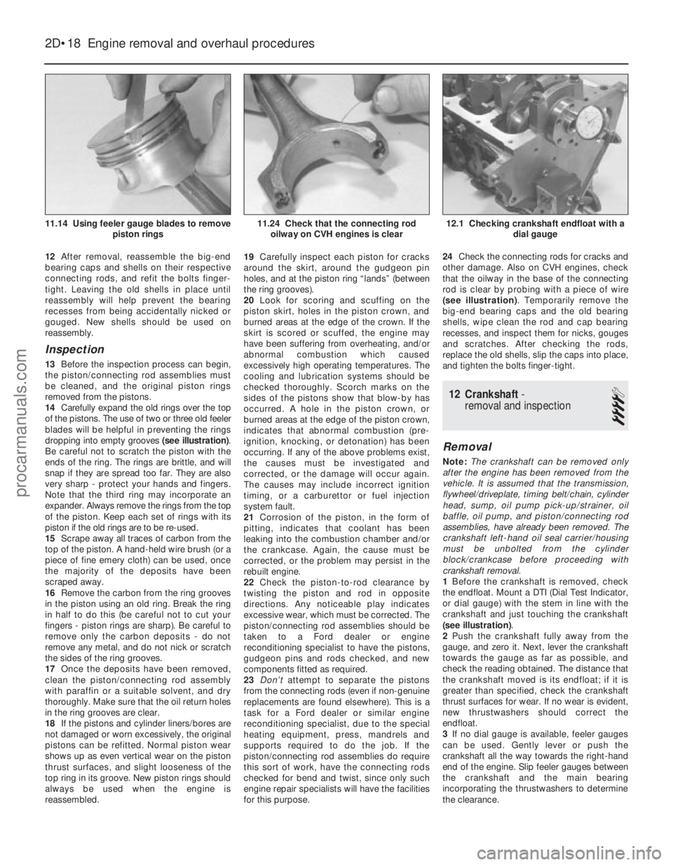
dropping into empty grooves (see illustration).
Be careful not to scratch the piston with the
ends of the ring. The rings are brittle, and will
snap if they are spread too far. They are also
very sharp - protect your hands and fingers.
Note that the third ring may incorporate an
expander. Always remove the rings from the top
of the piston. Keep each set of rings with its
piston if the old rings are to be re-used.
15 Scrape away all traces of carbon from the
top of the piston. A hand-held wire brush (or a
piece of fine emery cloth) can be used, once
the majority of the deposits have been
scraped away.
16 Remove the carbon from the ring grooves
in the piston using an old ring. Break the ring
in half to do this (be careful not to cut your
fingers - piston rings are sharp). Be careful to
remove only the carbon deposits - do not
remove any metal, and do not nick or scratch
the sides of the ring grooves.
17 Once the deposits have been removed,
clean the piston/connecting rod assembly
with paraffin or a suitable solvent, and dry
thoroughly. Make sure that the oil return holes
in the ring grooves are clear.
18 If the pistons and cylinder liners/bores are
not damaged or worn excessively, the original
pistons can be refitted. Normal piston wear
shows up as even vertical wear on the piston
thrust surfaces, and slight looseness of the
top ring in its groove. New piston rings should
always be used when the engine is
reassembled. 19
Carefully inspect each piston for cracks
around the skirt, around the gudgeon pin
holes, and at the piston ring “lands” (between
the ring grooves).
20 Look for scoring and scuffing on the
piston skirt, holes in the piston crown, and
burned areas at the edge of the crown. If the
skirt is scored or scuffed, the engine may
have been suffering from overheating, and/or
abnormal combustion which caused
excessively high operating temperatures. The
cooling and lubrication systems should be
checked thoroughly. Scorch marks on the
sides of the pistons show that blow-by has
occurred. A hole in the piston crown, or
burned areas at the edge of the piston crown,
indicates that abnormal combustion (pre-
ignition, knocking, or detonation) has been
occurring. If any of the above problems exist,
the causes must be investigated and
corrected, or the damage will occur again.
The causes may include incorrect ignition
timing, or a carburettor or fuel injection
system fault.
21 Corrosion of the piston, in the form of
pitting, indicates that coolant has been
leaking into the combustion chamber and/or
the crankcase. Again, the cause must be
corrected, or the problem may persist in the
rebuilt engine.
22 Check the piston-to-rod clearance by
twisting the piston and rod in opposite
directions. Any noticeable play indicates
excessive wear, which must be corrected. The
piston/connecting rod assemblies should be
taken to a Ford dealer or engine
reconditioning specialist to have the pistons,
gudgeon pins and rods checked, and new
components fitted as required.
23 Don’t attempt to separate the pistons
from the connecting rods (even if non-genuine
replacements are found elsewhere). This is a
task for a Ford dealer or similar engine
reconditioning specialist, due to the special
heating equipment, press, mandrels and
supports required to do the job. If the
piston/connecting rod assemblies do require
this sort of work, have the connecting rods
checked for bend and twist, since only such
engine repair specialists will have the facilities
for this purpose. 24
Check the connecting rods for cracks and
other damage. Also on CVH engines, check
that the oilway in the base of the connecting
rod is clear by probing with a piece of wire
(see illustration) . Temporarily remove the
big-end bearing caps and the old bearing
shells, wipe clean the rod and cap bearing
recesses, and inspect them for nicks, gouges
and scratches. After checking the rods,
replace the old shells, slip the caps into place,
and tighten the bolts finger-tight.
12 Crankshaft -
removal and inspection
4
Removal
Note: The crankshaft can be removed only
after the engine has been removed from the
vehicle. It is assumed that the transmission,
flywheel/driveplate, timing belt/chain, cylinder
head, sump, oil pump pick-up/strainer, oil
baffle, oil pump, and piston/connecting rod
assemblies, have already been removed. The
crankshaft left-hand oil seal carrier/housing
must be unbolted from the cylinder
block/crankcase before proceeding with
crankshaft removal.
1 Before the crankshaft is removed, check
the endfloat. Mount a DTI (Dial Test Indicator,
or dial gauge) with the stem in line with the
crankshaft and just touching the crankshaft
(see illustration) .
2 Push the crankshaft fully away from the
gauge, and zero it. Next, lever the crankshaft
towards the gauge as far as possible, and
check the reading obtained. The distance that
the crankshaft moved is its endfloat; if it is
greater than specified, check the crankshaft
thrust surfaces for wear. If no wear is evident,
new thrustwashers should correct the
endfloat.
3 If no dial gauge is available, feeler gauges
can be used. Gently lever or push the
crankshaft all the way towards the right-hand
end of the engine. Slip feeler gauges between
the crankshaft and the main bearing
incorporating the thrustwashers to determine
the clearance.
2D•18 Engine removal and overhaul procedures
12.1 Checking crankshaft endfloat with a dial gauge11.24 Check that the connecting rodoilway on CVH engines is clear11.14 Using feeler gauge blades to remove piston rings
1595Ford Fiesta Remakeprocarmanuals.com
http://vnx.su
Page 89 of 296
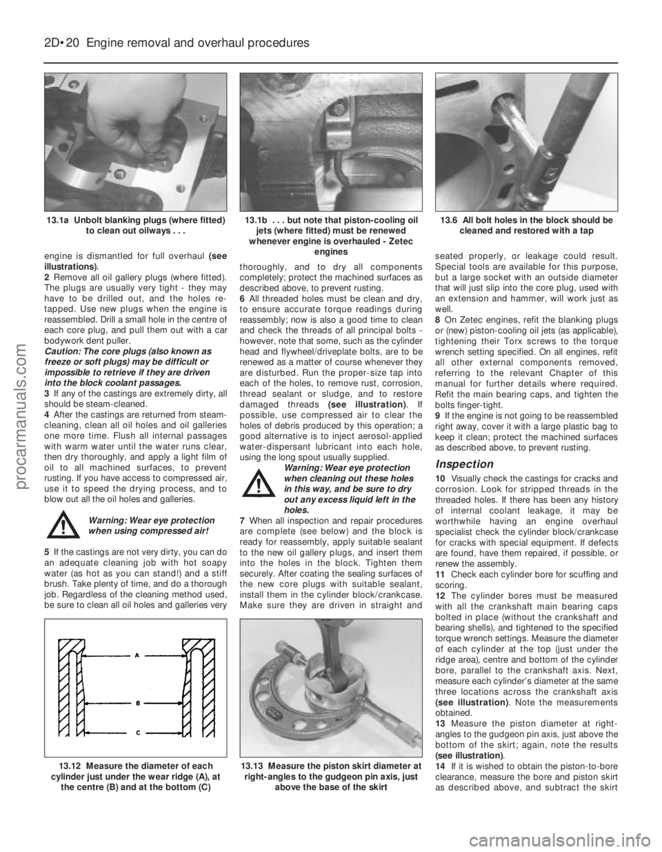
engine is dismantled for full overhaul (see
illustrations) .
2 Remove all oil gallery plugs (where fitted).
The plugs are usually very tight - they may
have to be drilled out, and the holes re-
tapped. Use new plugs when the engine is
reassembled. Drill a small hole in the centre of
each core plug, and pull them out with a car
bodywork dent puller.
Caution: The core plugs (also known as
freeze or soft plugs) may be difficult or
impossible to retrieve if they are driven
into the block coolant passages.
3 If any of the castings are extremely dirty, all
should be steam-cleaned.
4 After the castings are returned from steam-
cleaning, clean all oil holes and oil galleries
one more time. Flush all internal passages
with warm water until the water runs clear,
then dry thoroughly, and apply a light film of
oil to all machined surfaces, to prevent
rusting. If you have access to compressed air,
use it to speed the drying process, and to
blow out all the oil holes and galleries.
Warning: Wear eye protection
when using compressed air!
5 If the castings are not very dirty, you can do
an adequate cleaning job with hot soapy
water (as hot as you can stand!) and a stiff
brush. Take plenty of time, and do a thorough
job. Regardless of the cleaning method used,
be sure to clean all oil holes and galleries very thoroughly, and to dry all components
completely; protect the machined surfaces as
described above, to prevent rusting.
6
All threaded holes must be clean and dry,
to ensure accurate torque readings during
reassembly; now is also a good time to clean
and check the threads of all principal bolts -
however, note that some, such as the cylinder
head and flywheel/driveplate bolts, are to be
renewed as a matter of course whenever they
are disturbed. Run the proper-size tap into
each of the holes, to remove rust, corrosion,
thread sealant or sludge, and to restore
damaged threads (see illustration). If
possible, use compressed air to clear the
holes of debris produced by this operation; a
good alternative is to inject aerosol-applied
water-dispersant lubricant into each hole,
using the long spout usually supplied. Warning: Wear eye protection
when cleaning out these holes
in this way, and be sure to dry
out any excess liquid left in the
holes.
7 When all inspection and repair procedures
are complete (see below) and the block is
ready for reassembly, apply suitable sealant
to the new oil gallery plugs, and insert them
into the holes in the block. Tighten them
securely. After coating the sealing surfaces of
the new core plugs with suitable sealant,
install them in the cylinder block/crankcase.
Make sure they are driven in straight and seated properly, or leakage could result.
Special tools are available for this purpose,
but a large socket with an outside diameter
that will just slip into the core plug, used with
an extension and hammer, will work just as
well.
8
On Zetec engines, refit the blanking plugs
or (new) piston-cooling oil jets (as applicable),
tightening their Torx screws to the torque
wrench setting specified. On all engines, refit
all other external components removed,
referring to the relevant Chapter of this
manual for further details where required.
Refit the main bearing caps, and tighten the
bolts finger-tight.
9 If the engine is not going to be reassembled
right away, cover it with a large plastic bag to
keep it clean; protect the machined surfaces
as described above, to prevent rusting.
Inspection
10 Visually check the castings for cracks and
corrosion. Look for stripped threads in the
threaded holes. If there has been any history
of internal coolant leakage, it may be
worthwhile having an engine overhaul
specialist check the cylinder block/crankcase
for cracks with special equipment. If defects
are found, have them repaired, if possible, or
renew the assembly.
11 Check each cylinder bore for scuffing and
scoring.
12 The cylinder bores must be measured
with all the crankshaft main bearing caps
bolted in place (without the crankshaft and
bearing shells), and tightened to the specified
torque wrench settings. Measure the diameter
of each cylinder at the top (just under the
ridge area), centre and bottom of the cylinder
bore, parallel to the crankshaft axis. Next,
measure each cylinder’s diameter at the same
three locations across the crankshaft axis
(see illustration) . Note the measurements
obtained.
13 Measure the piston diameter at right-
angles to the gudgeon pin axis, just above the
bottom of the skirt; again, note the results
(see illustration) .
14 If it is wished to obtain the piston-to-bore
clearance, measure the bore and piston skirt
as described above, and subtract the skirt
2D•20 Engine removal and overhaul procedures
13.13 Measure the piston skirt diameter at
right-angles to the gudgeon pin axis, just
above the base of the skirt13.12 Measure the diameter of each
cylinder just under the wear ridge (A), at
the centre (B) and at the bottom (C)
13.6 All bolt holes in the block should be cleaned and restored with a tap13.1b . . . but note that piston-cooling oiljets (where fitted) must be renewed
whenever engine is overhauled - Zetec engines13.1a Unbolt blanking plugs (where fitted)to clean out oilways . . .
1595Ford Fiesta Remakeprocarmanuals.com
http://vnx.su
Page 94 of 296
Plastigauge to the scale printed on the
Plastigauge envelope, to obtain the running
clearance (see illustration 17.15) . Compare it
to the Specifications, to make sure the
clearance is correct.
14 If the clearance is not as specified, seek
the advice of a Ford dealer or similar engine
reconditioning specialist - if the crankshaft
journals are in good condition it may be
possible simply to renew the shells to achieve
the correct clearance. If this is not possible,
the crankshaft must be reground by a
specialist, who can also supply the necessary
undersized shells. First though, make sure
that no dirt or oil was trapped between the
bearing shells and the connecting rod or cap
when the clearance was measured. Also,
recheck the crankpin diameter. If the
Plastigauge was wider at one end than the
other, the crankpin journal may be tapered.
15 Carefully scrape all traces of the
Plastigauge material off the journal and the
bearing surface. Be very careful not to scratch
the bearing - use your fingernail or the edge of a credit card.
Final piston/connecting rod
refitting
16 Make sure the bearing surfaces are
perfectly clean, then apply a uniform layer of
clean molybdenum disulphide-based grease,
engine assembly lubricant, or clean engine oil,
to both of them. You’ll have to push the piston
into the cylinder to expose the bearing surface
of the shell in the connecting rod.
17 Slide the connecting rod back into place
on the crankpin (big-end) journal, refit the big-
end bearing cap, and then tighten the bolts as
described above.
18 Repeat the entire procedure for the
remaining piston/connecting rod assemblies.
19 The important points to remember are:
a) Keep the backs of the bearing shells and the recesses of the connecting rods and
caps perfectly clean when assembling
them.
b) Make sure you have the correct
piston/rod assembly for each cylinder -
use the etched cylinder numbers to
identify the front-facing side of both the
rod and its cap.
c) The arrow on the piston crown must face the timing belt/chain end of the engine.
d) Lubricate the cylinder bores with clean
engine oil.
e) Lubricate the bearing surfaces when refitting the big-end bearing caps after the
running clearance has been checked. 20
After all the piston/connecting rod
assemblies have been properly installed,
rotate the crankshaft a number of times by
hand, to check for any obvious binding.
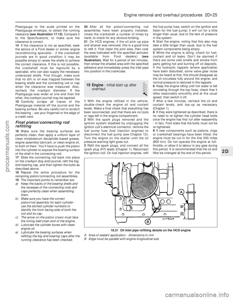
21 On HCS engines, if the oil pick-up pipe
and strainer was removed, this is a good time
to refit it. First clean the joint area, then coat
the area indicated with the specified activator
(available from Ford dealers) (see
illustration) . Wait for a period of ten minutes,
then smear the shaded area with the specified
adhesive and immediately press the inlet pipe
into position in the crankcase.
19 Engine - initial start-up after
overhaul
1
1 With the engine refitted in the vehicle,
double-check the engine oil and coolant
levels. Make a final check that everything has
been reconnected, and that there are no tools
or rags left in the engine compartment.
2 With the spark plugs removed and the
ignition system disabled by unplugging the
ignition coil’s electrical connector, remove the
fuel pump fuse (fuel injection engines) to
disconnect the fuel pump (see Chapter 12).
Turn the engine on the starter until the oil
pressure warning light goes out.
3 Refit the spark plugs, and connect all the
spark plug (HT) leads (Chapter 1). Reconnect
the ignition coil. On fuel injection engines, refit the fuel pump fuse, switch on the ignition and
listen for the fuel pump; it will run for a little
longer than usual, due to the lack of pressure
in the system.
4
Start the engine, noting that this also may
take a little longer than usual, due to the fuel
system components being empty.
5 While the engine is idling, check for fuel,
coolant and oil leaks. Don’t be alarmed if
there are some odd smells and smoke from
parts getting hot and burning off oil deposits.
If the hydraulic tappets (where applicable)
have been disturbed, some valve gear noise
may be heard at first; this should disappear as
the oil circulates fully around the engine, and
normal pressure is restored in the tappets.
6 Keep the engine idling until hot water is felt
circulating through the top hose, check that it
idles reasonably smoothly and at the usual
speed, then switch it off.
7 After a few minutes, recheck the oil and
coolant levels, and top-up as necessary
(Chapter 1).
8 If they were tightened as described, there is
no need to re-tighten the cylinder head bolts
once the engine has first run after reassembly
- in fact, Ford state that the bolts must notbe
re-tightened.
9 If new components such as pistons, rings
or crankshaft bearings have been fitted, the
engine must be run-in for the first 500 miles
(800 km). Do not operate the engine at full-
throttle, or allow it to labour in any gear during
this period. It is recommended that the oil and
filter be changed at the end of this period.
Engine removal and overhaul procedures 2D•25
18.21 Oil inlet pipe refitting details on the HCS engine
A Area of sealant application - dimensions in mm
B Edge must be parallel with engine longitudinal axis
2D
1595Ford Fiesta Remakeprocarmanuals.com
http://vnx.su
Page 96 of 296

3
1595Ford Fiesta Remake
Coolant
Mixture type . . . . . . . . . . . . . . . . . . . . . . . . . . . . . . . . . . . .\
. . . . . . . . . . See Chapter 1
Cooling system capacity . . . . . . . . . . . . . . . . . . . . . . . . . . . . . . . . . . . .\
See Chapter 1
System pressure
Pressure test . . . . . . . . . . . . . . . . . . . . . . . . . . . . . . . . . . . .\
. . . . . . . . . . 1.2 bars - should hold this pressure for at least 10 seconds
Expansion tank filler cap
Pressure rating . . . . . . . . . . . . . . . . . . . . . . . . . . . . . . . . . . . .\
. . . . . . . . 1.0 to 1.4 bars approximately - see cap for actual value
Thermostat
Starts to open . . . . . . . . . . . . . . . . . . . . . . . . . . . . . . . . . . . .\
. . . . . . . . . 85ºC to 89ºC
Coolant temperature sensor
Resistance:At 0ºC . . . . . . . . . . . . . . . . . . . . . . . . . . . . . . . . . . . .\
. . . . . . . . . . . . . 89 to 102 kilohms
At 20ºC . . . . . . . . . . . . . . . . . . . . . . . . . . . . . . . . . . . .\
. . . . . . . . . . . . 35 to 40 kilohms
At 100ºC . . . . . . . . . . . . . . . . . . . . . . . . . . . . . . . . . . . .\
. . . . . . . . . . . 1.9 to 2.5 kilohms
At 120ºC . . . . . . . . . . . . . . . . . . . . . . . . . . . . . . . . . . . .\
. . . . . . . . . . . 1.0 to 1.4 kilohms
Chapter 3
Cooling, heating and ventilation systems
Antifreeze - general information . . . . . . . . . . . . . . . . . . . . . . . . . . . . 2
Auxiliary drivebelt check and renewal . . . . . . . . . . . . . . .See Chapter 1
Coolant level check . . . . . . . . . . . . . . . . . . . . . . .See
“Weekly Checks”
Cooling system - draining . . . . . . . . . . . . . . . . . . . . . . . .See Chapter 1
Cooling system - filling . . . . . . . . . . . . . . . . . . . . . . . . . .See Chapter 1
Cooling system - flushing . . . . . . . . . . . . . . . . . . . . . . . .See Chapter 1
Cooling system electrical switches and sensors - testing, removal and refitting . . . . . . . . . . . . . . . . . . . . . . . . . . . . . . . . . . . .\
. . . . . . 6
Cooling system hoses - disconnection and renewal . . . . . . . . . . . . 3
General information and precautions . . . . . . . . . . . . . . . . . . . . . . . . 1 Heater/ventilation components - removal and refitting . . . . . . . . . . . 11
Radiator and expansion tank - removal, inspection and refitting . . . 7
Radiator electric cooling fan assembly - testing, removal and
refitting . . . . . . . . . . . . . . . . . . . . . . . . . . . . . . . . . . . .\
. . . . . . . . . . 5
Thermostat - removal, testing and refitting . . . . . . . . . . . . . . . . . . . . 4
Underbonnet check for fluid leaks and hose condition . .See Chapter 1
Water pump (CVH and PTE engines) - removal and refitting . . . . . . 9
Water pump (HCS engines) - removal and refitting . . . . . . . . . . . . . 8
Water pump (Zetec engines) - removal and refitting . . . . . . . . . . . . . 10
3•1
Specifications Contents
Easy, suitable for
novice with little
experience Fairly easy,
suitable
for beginner with
some experience Fairly difficult,
suitable for competent
DIY mechanic
Difficult,
suitable for
experienced DIY
mechanic Very difficult,
suitable for expert DIY
or professional
Degrees of difficulty
54321
procarmanuals.com
http://vnx.su
Page 97 of 296

Torque wrench settingsNmlbf ft
Thermostat housing to cylinder head: HCS engines . . . . . . . . . . . . . . . . . . . . . . . . . . . . . . . . . . . .\
. . . . . . . . 17 to 21 13 to 16
CVH engines . . . . . . . . . . . . . . . . . . . . . . . . . . . . . . . . . . . .\
. . . . . . . . 9 to 12 7 to 9
PTE engines . . . . . . . . . . . . . . . . . . . . . . . . . . . . . . . . . . . .\
. . . . . . . . 9 7
Zetec engines . . . . . . . . . . . . . . . . . . . . . . . . . . . . . . . . . . . .\
. . . . . . . 17 to 21 13 to 16
Water outlet to thermostat housing (Zetec engines) . . . . . . . . . . . . . . . 9 to 12 7 to 9
Water pump pulley . . . . . . . . . . . . . . . . . . . . . . . . . . . . . . . . . . . .\
. . . . . 107.5
Water pump retaining bolts: HCS, CVH and PTE engines . . . . . . . . . . . . . . . . . . . . . . . . . . . . . . . . 8 6
Zetec engines . . . . . . . . . . . . . . . . . . . . . . . . . . . . . . . . . . . .\
. . . . . . . 1813
Coolant temperature gauge sender . . . . . . . . . . . . . . . . . . . . . . . . . . . . 6 4
Coolant temperature sensor: HCS engines . . . . . . . . . . . . . . . . . . . . . . . . . . . . . . . . . . . .\
. . . . . . . . 2317
CVH engines: 1.4 litre models . . . . . . . . . . . . . . . . . . . . . . . . . . . . . . . . . . . .\
. . . . 1914
1.6 litre models . . . . . . . . . . . . . . . . . . . . . . . . . . . . . . . . . . . .\
. . . . 1511
PTE engines . . . . . . . . . . . . . . . . . . . . . . . . . . . . . . . . . . . .\
. . . . . . . . 1511
Zetec engines . . . . . . . . . . . . . . . . . . . . . . . . . . . . . . . . . . . .\
. . . . . . . 1511
Radiator mounting bolts . . . . . . . . . . . . . . . . . . . . . . . . . . . . . . . . . . . .\
. 20 to 27 15 to 20
Radiator cooling fan shroud retaining bolt . . . . . . . . . . . . . . . . . . . . . . . 3 to 5 2 to 4
Radiator cooling fan motor to shroud nuts . . . . . . . . . . . . . . . . . . . . . . . 9 to 12 7 to 9
Automatic transmission fluid cooling pipe connections to radiator . . . . 17 to 21 13 to 16
3•2 Cooling, heating and ventilation systems
1595Ford Fiesta Remake
1 General information and
precautions
Engine cooling system
The cooling system is of the pressurised
type consisting of a belt-driven pump,
aluminium crossflow radiator, expansion tank,
electric cooling fan and a thermostat. The
system functions as follows. Cold coolant in
the bottom of the radiator passes through the
bottom hose to the water pump, where it is
pumped around the cylinder block and head
passages. After cooling the cylinder bores,
combustion surfaces and valve seats, the
coolant reaches the underside of the
thermostat, which is initially closed. The
coolant passes through the heater and
inlet manifold and is returned to the water
pump. When the engine is cold, the coolant
circulates through the cylinder block, cylinder
head, heater and inlet manifold. When the
coolant reaches a predetermined tempera-
ture, the thermostat opens, and the coolant
then passes through the top hose to
the radiator. As the coolant circulates
through the radiator, it is cooled by the inrush
of air when the car is in forward motion.
Airflow is supplemented by the action of the
electric cooling fan when necessary. Upon
reaching the bottom of the radiator, the
coolant is now cooled, and the cycle is
repeated. When the engine is at normal operating
temperature, the coolant expands, and some
of it is displaced into the expansion tank. This
coolant collects in the tank, and is returned to
the radiator when the system cools.
The electric cooling fan, mounted behind
the radiator, is controlled by a thermostatic switch. At a predetermined coolant
temperature, the switch contacts close, thus
actuating the fan.
Heating/ventilation system
The heating system consists of a blower fan
and heater matrix (radiator) located in the
heater unit, with hoses connecting the heater
matrix to the engine cooling system. Hot
engine coolant is circulated through the
heater matrix. Air is forced through the matrix
by the three-speed fan, dispersing the heat
into the vehicle interior. Fresh air enters the
vehicle through the grille slats between the
windscreen and the rear edge of the bonnet,
and passes through to the heater casing.
Depending on the position of the heater slide
controls, which actuate cable-controlled flap
valves within the heater casing, the air is
distributed, either heated or unheated, via the
ducting to outlet vents. The main outlet vents
in the facia are adjustable. The airflow passes
through the passenger compartment to exit at
the rear of the vehicle.
Precautions
Warning: DO NOT attempt to
remove the expansion tank filler
cap, or to disturb any part of the
cooling system, while it or the
engine is hot, as there is a very great risk
of scalding. If the expansion tank filler cap
must be removed before the engine and
radiator have fully cooled down (even
though this is not recommended) the
pressure in the cooling system must first
be released. Cover the cap with a thick
layer of cloth, to avoid scalding, and slowly
unscrew the filler cap until a hissing sound
can be heard. When the hissing has
stopped, showing that pressure is
released, slowly unscrew the filler cap
further until it can be removed; if more
hissing sounds are heard, wait until they have stopped before unscrewing the cap
completely. At all times, keep well away
from the filler opening.
Warning: Do not allow antifreeze
to come in contact with your
skin, or with the painted
surfaces of the vehicle. Rinse off
spills immediately with plenty of water.
Never leave antifreeze lying around in an
open container, or in a puddle in the
driveway or on the garage floor. Children
and pets are attracted by its sweet smell,
but antifreeze can be fatal if ingested. Warning: If the engine is hot, the
electric cooling fan may start
rotating even if the engine is not
running, so be careful to keep
hands, hair and loose clothing well clear
when working in the engine compartment.
2 Antifreeze -
general information
Note: Refer to the warnings given in Section 1
of this Chapter before proceeding. The cooling system should be filled with a
water/ethylene glycol-based antifreeze
solution, of a strength which will prevent
freezing down to at least -25ºC, or lower if the
local climate requires it. Antifreeze also
provides protection against corrosion, and
increases the coolant boiling point. The cooling system should be maintained
according to the schedule described in
Chapter 1. If antifreeze is used that is not to
Ford’s specification, old or contaminated
coolant mixtures are likely to cause damage,
and encourage the formation of corrosion and
scale in the system. Use distilled water with the
antifreeze, if available - if not, be sure to use
only soft water. Clean rainwater is suitable.
procarmanuals.com
http://vnx.su
Page 98 of 296
Before adding antifreeze, check all hoses
and hose connections, because antifreeze
tends to leak through very small openings.
Engines don’t normally consume coolant, so if
the level falls regularly, find the cause and
correct it. The exact mixture of antifreeze-to-water
which you should use depends on the relative
weather conditions. The mixture should
contain at least 40% antifreeze, but not more
than 70%. Consult the mixture ratio chart on
the antifreeze container before adding
coolant. Hydrometers are available at most
automotive accessory shops to test the
coolant. Use only good-quality ethylene-
glycol-based antifreeze which meets the
vehicle manufacturer’s specifications.
3 Cooling system hoses -
disconnection and renewal
1
Note: Refer to the warnings given in Section 1
of this Chapter before starting work.
1 If the checks described in Chapter 1 reveal
a faulty hose, it must be renewed as follows.
2 First drain the cooling system (see Chap-
ter 1); if the antifreeze is not due for renewal,
the drained coolant may be re-used, if it is
collected in a clean container.
3 To disconnect any hose, use a pair of pliers
to release the spring clamps (or a screwdriver
to slacken screw-type clamps), then move
them along the hose clear of the union.
Carefully work the hose off its stubs. The
hoses can be removed with relative ease
when new - on an older car, they may have
stuck.
4 If a hose proves stubborn, try to release it
by rotating it on its unions before attempting
to work it off. Gently prise the end of the hose
with a blunt instrument (such as a flat-bladed
screwdriver), but do not apply too much force,
and take care not to damage the pipe stubs or
hoses. Note in particular that the radiator hose
unions are fragile; do not use excessive force
when attempting to remove the hoses.
5 When refitting a hose, first slide the clamps
onto the hose, then work the hose onto its
unions. 6
Work each hose end fully onto its union,
then check that the hose is settled correctly
and is properly routed. Slide each clip along
the hose until it is behind the union flared end,
before tightening it securely.
7 Refill the system with coolant (see Chap-
ter 1).
8 Check carefully for leaks as soon as
possible after disturbing any part of the
cooling system.
4 Thermostat -
removal, testing and refitting
1
Note: Refer to the warnings given in Section 1
of this Chapter before starting work.
Removal
1 Disconnect the battery negative (earth) lead
(refer to Chapter 5A, Section 1).
2 Drain the cooling system (see Chapter 1).
3 Refer to the relevant Part of Chapter 4 and
remove the air cleaner or air inlet hoses,
according to engine type as necessary, to
gain access to the thermostat housing.
HCS, CVH and PTE engines
4 Loosen the clips, and disconnect the
radiator top hose, expansion tank hose and,
where applicable, the heater hose from the
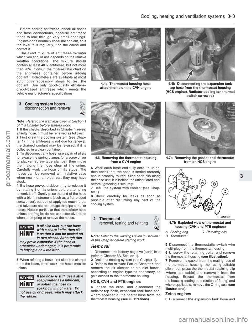
thermostat housing (see illustrations).5
Disconnect the thermostatic switch wire
multi-plug from the thermostat housing.
6 Unscrew the retaining bolts, and remove
the thermostat housing (see illustration).
7 Remove the gasket from the mating face of
the thermostat housing, then using suitable
pliers, compress the thermostat retaining clip
(where applicable) and remove it from the
housing. Extract the thermostat from
the housing (noting its direction of fitting) and
where applicable, remove the O-ring seal (see
illustrations) .
Zetec engines
8Disconnect the expansion tank hose and
Cooling, heating and ventilation systems 3•3
4.4b Disconnecting the expansion tank
top hose from the thermostat housing
(HCS engine). Radiator cooling fan thermal switch (arrowed)4.4a Thermostat housing hose
attachments on the CVH engine
4.7b Exploded view of thermostat and housing (CVH and PTE engines)
A Sealing ring C Retaining clip
B Thermostat
4.7a Removing the gasket and thermostat from an HCS engine4.6 Removing the thermostat housingfrom a CVH engine
3
1595Ford Fiesta Remake
If all else fails, cut the hose
with a sharp knife, then slit
it so that it can be peeled off
in two pieces. Although this
may prove expensive if the hose is
otherwise undamaged, it is preferable
to buying a new radiator.
If the hose is stiff, use a little
soapy water as a lubricant,
or soften the hose by
soaking it in hot water. Do
not use oil or grease, which may attack
the rubber.
procarmanuals.com
http://vnx.su
Page 99 of 296
the radiator top hose from the thermostat
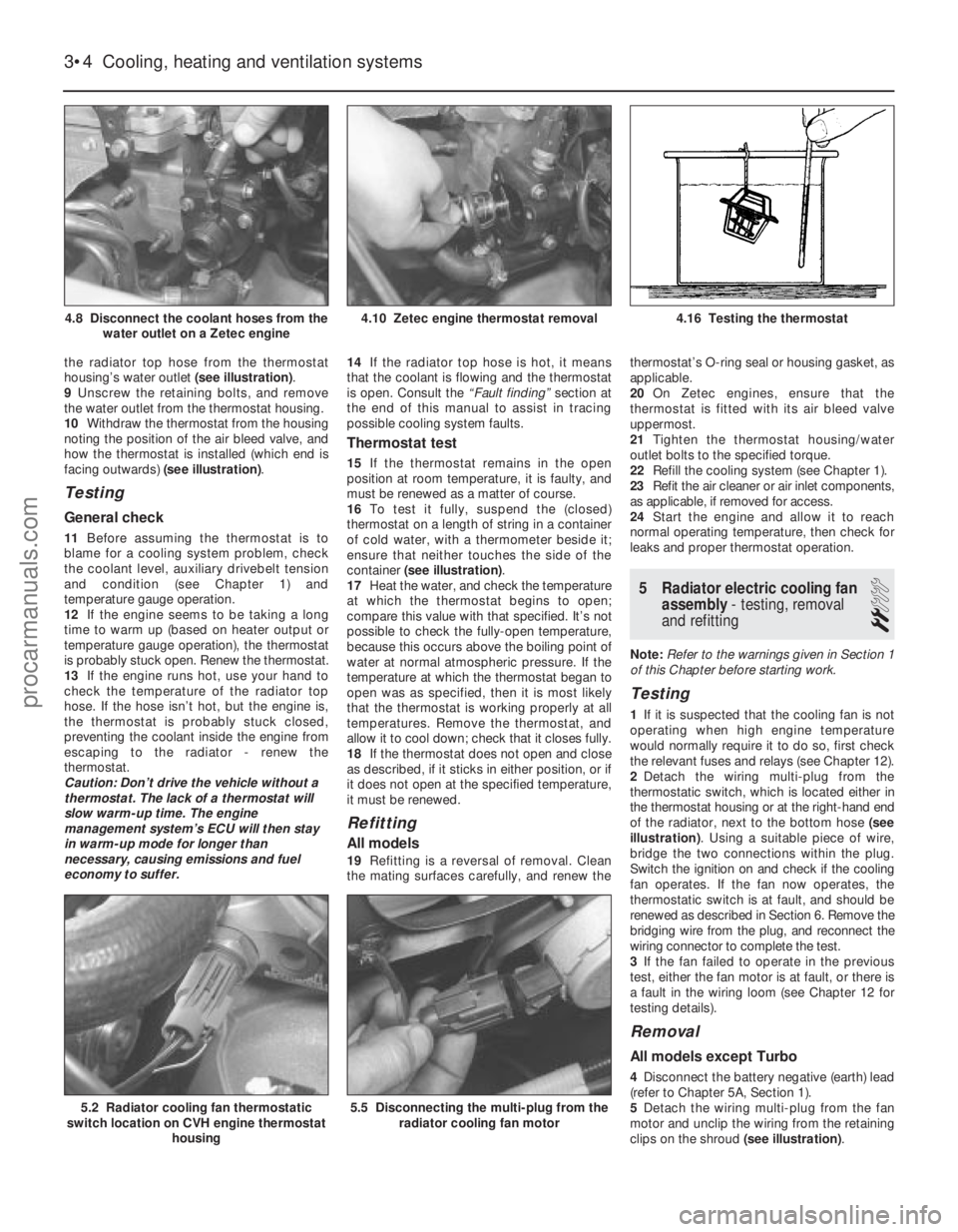
housing’s water outlet (see illustration).
9 Unscrew the retaining bolts, and remove
the water outlet from the thermostat housing.
10 Withdraw the thermostat from the housing
noting the position of the air bleed valve, and
how the thermostat is installed (which end is
facing outwards) (see illustration).
Testing
General check
11Before assuming the thermostat is to
blame for a cooling system problem, check
the coolant level, auxiliary drivebelt tension
and condition (see Chapter 1) and
temperature gauge operation.
12 If the engine seems to be taking a long
time to warm up (based on heater output or
temperature gauge operation), the thermostat
is probably stuck open. Renew the thermostat.
13 If the engine runs hot, use your hand to
check the temperature of the radiator top
hose. If the hose isn’t hot, but the engine is,
the thermostat is probably stuck closed,
preventing the coolant inside the engine from
escaping to the radiator - renew the
thermostat.
Caution: Don’t drive the vehicle without a
thermostat. The lack of a thermostat will
slow warm-up time. The engine
management system’s ECU will then stay
in warm-up mode for longer than
necessary, causing emissions and fuel
economy to suffer. 14
If the radiator top hose is hot, it means
that the coolant is flowing and the thermostat
is open. Consult the “Fault finding” section at
the end of this manual to assist in tracing
possible cooling system faults.
Thermostat test
15 If the thermostat remains in the open
position at room temperature, it is faulty, and
must be renewed as a matter of course.
16 To test it fully, suspend the (closed)
thermostat on a length of string in a container
of cold water, with a thermometer beside it;
ensure that neither touches the side of the
container (see illustration) .
17 Heat the water, and check the temperature
at which the thermostat begins to open;
compare this value with that specified. It’s not
possible to check the fully-open temperature,
because this occurs above the boiling point of
water at normal atmospheric pressure. If the
temperature at which the thermostat began to
open was as specified, then it is most likely
that the thermostat is working properly at all
temperatures. Remove the thermostat, and
allow it to cool down; check that it closes fully.
18 If the thermostat does not open and close
as described, if it sticks in either position, or if
it does not open at the specified temperature,
it must be renewed.
Refitting
All models
19 Refitting is a reversal of removal. Clean
the mating surfaces carefully, and renew the thermostat’s O-ring seal or housing gasket, as
applicable.
20
On Zetec engines, ensure that the
thermostat is fitted with its air bleed valve
uppermost.
21 Tighten the thermostat housing/water
outlet bolts to the specified torque.
22 Refill the cooling system (see Chapter 1).
23 Refit the air cleaner or air inlet components,
as applicable, if removed for access.
24 Start the engine and allow it to reach
normal operating temperature, then check for
leaks and proper thermostat operation.
5 Radiator electric cooling fan assembly - testing, removal
and refitting
2
Note: Refer to the warnings given in Section 1
of this Chapter before starting work.
Testing
1 If it is suspected that the cooling fan is not
operating when high engine temperature
would normally require it to do so, first check
the relevant fuses and relays (see Chapter 12).
2 Detach the wiring multi-plug from the
thermostatic switch, which is located either in
the thermostat housing or at the right-hand end
of the radiator, next to the bottom hose (see
illustration) . Using a suitable piece of wire,
bridge the two connections within the plug.
Switch the ignition on and check if the cooling
fan operates. If the fan now operates, the
thermostatic switch is at fault, and should be
renewed as described in Section 6. Remove the
bridging wire from the plug, and reconnect the
wiring connector to complete the test.
3 If the fan failed to operate in the previous
test, either the fan motor is at fault, or there is
a fault in the wiring loom (see Chapter 12 for
testing details).
Removal
All models except Turbo
4 Disconnect the battery negative (earth) lead
(refer to Chapter 5A, Section 1).
5 Detach the wiring multi-plug from the fan
motor and unclip the wiring from the retaining
clips on the shroud (see illustration).
3•4 Cooling, heating and ventilation systems
5.5 Disconnecting the multi-plug from the
radiator cooling fan motor5.2 Radiator cooling fan thermostatic
switch location on CVH engine thermostat
housing
4.16 Testing the thermostat4.10 Zetec engine thermostat removal4.8 Disconnect the coolant hoses from thewater outlet on a Zetec engine
1595Ford Fiesta Remakeprocarmanuals.com
http://vnx.su