1989 FORD FIESTA engine coolant
[x] Cancel search: engine coolantPage 156 of 296
d)Refit the remaining parts in the reverse
order of removal. Tighten all fasteners to
the specified torque wrench settings
where given.
e) Where drained, refill the cooling system (see Chapter 1).
f) Run the engine, and check for exhaust
leaks. Check the coolant level when fully
warmed-up to normal operating
temperature.
4 Catalytic converter - general
information and precautions
The catalytic converter is a reliable and
simple device, which needs no maintenance
in itself, but there are some facts of which an
owner should be aware if the converter is to
function properly for its full service life. a) DO NOT use leaded petrol in a vehicle equipped with a catalytic converter - the
lead will coat the precious metals,
reducing their converting efficiency, and
will eventually destroy the converter.
b) Always keep the ignition and fuel systems
well-maintained in accordance with the
manufacturer’s schedule (see Chapter 1).
c) If the engine develops a misfire, do not drive the vehicle at all (or at least as little
as possible) until the fault is cured.
d) DO NOT push - or tow-start the vehicle -
this will soak the catalytic converter in
unburned fuel, causing it to overheat
when the engine does start.
e) DO NOT switch off the ignition at high engine speeds, ie do not “blip” the
throttle immediately before switching off.
f) DO NOT use fuel or engine oil additives - these may contain substances harmful to
the catalytic converter.
g) DO NOT continue to use the vehicle if the
engine burns oil to the extent of leaving a
visible trail of blue smoke.
h) Remember that the catalytic converter
operates at very high temperatures. DO
NOT, therefore, park the vehicle in dry
undergrowth, over long grass or piles of
dead leaves, after a long run.
I) Remember that the catalytic converter is FRAGILE. Do not strike it with tools
during servicing work.
j) In some cases, a sulphurous smell (like
that of rotten eggs) may be noticed from
the exhaust. This is common to many
catalytic converter-equipped vehicles.
Once the vehicle has covered a few
thousand miles, the problem should
disappear. Low quality fuel with a high
sulphur content will exacerbate this effect.
k) The catalytic converter used on a well-
maintained and well-driven vehicle should
last for between 50 000 and
100 000 miles. If the converter is no
longer effective, it must be renewed.
5 Positive crankcase ventilation system - checking
and component renewal
2
Checking
1 Checking procedures for the system
components are included in Chapter 1.
Component renewal - all
engines except Zetec
Air cleaner components
2 See Chapter 1.
Filter/oil separator and hoses
3All the components relating to the positive
crankcase ventilation system, with the
exception of the HCS engine filter/adapter
located on the underside of the air cleaner,
may be removed by simple disconnection and
withdrawal (having noted all connections for
subsequent refitting).
4 The refitting of all components is a reversal
of the removal procedure, ensuring that the
connections are correctly made.
Component renewal - Zetec
engines
Air cleaner components
5 See Chapter 1.
Positive Crankcase Ventilation (PCV)
valve
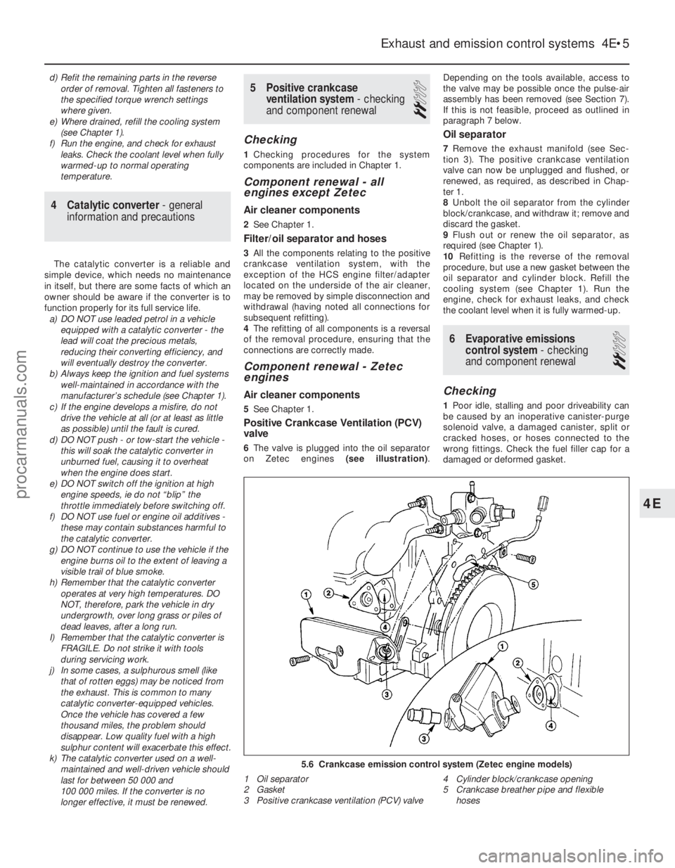
6The valve is plugged into the oil separator
on Zetec engines (see illustration).Depending on the tools available, access to
the valve may be possible once the pulse-air
assembly has been removed (see Section 7).
If this is not feasible, proceed as outlined in
paragraph 7 below.
Oil separator
7
Remove the exhaust manifold (see Sec-
tion 3). The positive crankcase ventilation
valve can now be unplugged and flushed, or
renewed, as required, as described in Chap-
ter 1.
8 Unbolt the oil separator from the cylinder
block/crankcase, and withdraw it; remove and
discard the gasket.
9 Flush out or renew the oil separator, as
required (see Chapter 1).
10 Refitting is the reverse of the removal
procedure, but use a new gasket between the
oil separator and cylinder block. Refill the
cooling system (see Chapter 1). Run the
engine, check for exhaust leaks, and check
the coolant level when it is fully warmed-up.
6 Evaporative emissions control system - checking
and component renewal
2
Checking
1 Poor idle, stalling and poor driveability can
be caused by an inoperative canister-purge
solenoid valve, a damaged canister, split or
cracked hoses, or hoses connected to the
wrong fittings. Check the fuel filler cap for a
damaged or deformed gasket.
Exhaust and emission control systems 4E•5
5.6 Crankcase emission control system (Zetec engine models)
1 Oil separator
2 Gasket
3 Positive crankcase ventilation (PCV) valve 4 Cylinder block/crankcase opening
5 Crankcase breather pipe and flexible
hoses
4E
1595Ford Fiesta Remakeprocarmanuals.com
http://vnx.su
Page 158 of 296
10Refitting is the reverse of the removal
procedure.
Pulse-air valve, filter and housing
(Zetec engines)
11 Disconnect the battery negative (earth)
lead (refer to Chapter 5A, Section 1).
12 Chock the rear wheels then jack up the
front of the car and support it on axle stands
(see “Jacking and vehicle support” ).
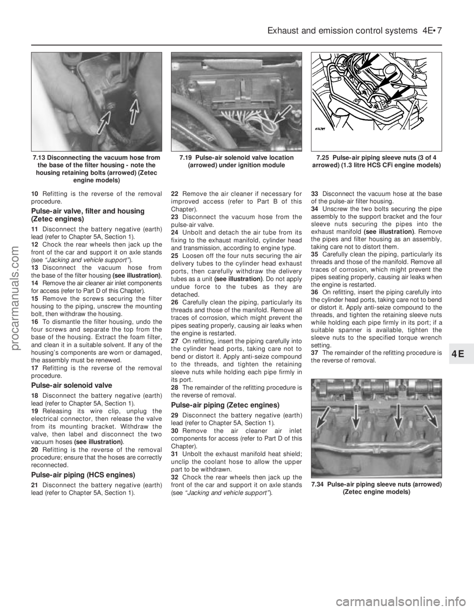
13 Disconnect the vacuum hose from
the base of the filter housing (see illustration).
14 Remove the air cleaner air inlet components
for access (refer to Part D of this Chapter).
15 Remove the screws securing the filter
housing to the piping, unscrew the mounting
bolt, then withdraw the housing.
16 To dismantle the filter housing, undo the
four screws and separate the top from the
base of the housing. Extract the foam filter,
and clean it in a suitable solvent. If any of the
housing’s components are worn or damaged,
the assembly must be renewed.
17 Refitting is the reverse of the removal
procedure.
Pulse-air solenoid valve
18 Disconnect the battery negative (earth)
lead (refer to Chapter 5A, Section 1).
19 Releasing its wire clip, unplug the
electrical connector, then release the valve
from its mounting bracket. Withdraw the
valve, then label and disconnect the two
vacuum hoses (see illustration) .
20 Refitting is the reverse of the removal
procedure; ensure that the hoses are correctly
reconnected.
Pulse-air piping (HCS engines)
21 Disconnect the battery negative (earth)
lead (refer to Chapter 5A, Section 1). 22
Remove the air cleaner if necessary for
improved access (refer to Part B of this
Chapter).
23 Disconnect the vacuum hose from the
pulse-air valve.
24 Unbolt and detach the air tube from its
fixing to the exhaust manifold, cylinder head
and transmission, according to engine type.
25 Loosen off the four nuts securing the air
delivery tubes to the cylinder head exhaust
ports, then carefully withdraw the delivery
tubes as a unit (see illustration) . Do not apply
undue force to the tubes as they are
detached.
26 Carefully clean the piping, particularly its
threads and those of the manifold. Remove all
traces of corrosion, which might prevent the
pipes seating properly, causing air leaks when
the engine is restarted.
27 On refitting, insert the piping carefully into
the cylinder head ports, taking care not to
bend or distort it. Apply anti-seize compound
to the threads, and tighten the retaining
sleeve nuts while holding each pipe firmly in
its port.
28 The remainder of the refitting procedure is
the reverse of removal.
Pulse-air piping (Zetec engines)
29 Disconnect the battery negative (earth)
lead (refer to Chapter 5A, Section 1).
30 Remove the air cleaner air inlet
components for access (refer to Part D of this
Chapter).
31 Unbolt the exhaust manifold heat shield;
unclip the coolant hose to allow the upper
part to be withdrawn.
32 Chock the rear wheels then jack up the
front of the car and support it on axle stands
(see “Jacking and vehicle support” ).33
Disconnect the vacuum hose at the base
of the pulse-air filter housing.
34 Unscrew the two bolts securing the pipe
assembly to the support bracket and the four
sleeve nuts securing the pipes into the
exhaust manifold (see illustration). Remove
the pipes and filter housing as an assembly,
taking care not to distort them.
35 Carefully clean the piping, particularly its
threads and those of the manifold. Remove all
traces of corrosion, which might prevent the
pipes seating properly, causing air leaks when
the engine is restarted.
36 On refitting, insert the piping carefully into
the cylinder head ports, taking care not to bend
or distort it. Apply anti-seize compound to the
threads, and tighten the retaining sleeve nuts
while holding each pipe firmly in its port; if a
suitable spanner is available, tighten the
sleeve nuts to the specified torque wrench
setting.
37 The remainder of the refitting procedure is
the reverse of removal.
Exhaust and emission control systems 4E•7
7.25 Pulse-air piping sleeve nuts (3 of 4
arrowed) (1.3 litre HCS CFi engine models)7.19 Pulse-air solenoid valve location (arrowed) under ignition module7.13 Disconnecting the vacuum hose fromthe base of the filter housing - note the
housing retaining bolts (arrowed) (Zetec engine models)
7.34 Pulse-air piping sleeve nuts (arrowed)
(Zetec engine models)
4E
1595Ford Fiesta Remakeprocarmanuals.com
http://vnx.su
Page 170 of 296
flux can pass between the magnet and the
sensor. When a trigger vane segment is in line
with the sensor, the magnetic flux is diverted
through the trigger vane, away from the
sensor. The sensor detects the change in
magnetic flux and sends an impulse to the
EEC IV module. Additional data is received
from the engine coolant temperature sensor,
manifold absolute pressure sensor, inlet air
temperature sensor, throttle position sensor
and vehicle speed sensor. Using this
information the EEC IV module calculates the
optimum ignition advance setting and
switches off the low tension circuit via the
ignition module. This results in the collapse of
the magnetic field in the coil which generates
the high tension voltage. The high tension
voltage is then fed, via the coil HT lead and
the carbon brush in the centre of the
distributor cap, to the rotor arm. The voltage
passes across to the appropriate metal
segment in the cap and via the spark plug HT
lead to the spark plug where it finally jumps
the spark plug gap to earth. It can be seen
that the ignition module functions basically as
a high current switch by controlling the low
tension supply to the ignition coil primary
windings.In the event of failure of a sensor, the
EEC IV module will substitute a preset value
for that input to allow the system to continue
to function. In the event of failure of the
EEC IV module, a “limited operation strategy”
(LOS) function allows the vehicle to be driven,
albeit at reduced power and efficiency. The
EEC IV module also has a “keep alive
memory” (KAM) function which stores idle and
drive values and codes which can be used to
indicate any system fault which may occur.
Distributorless ignition systems
The main ignition system components
include the ignition switch, the battery, the
crankshaft speed/position sensor, the ignition
module, the coil, the primary (low tension/LT)
and secondary (high tension/HT) wiring
circuits, and the spark plugs. The system used on carburettor models is
termed DIS (Distributorless Ignition System),
and on fuel injection models E-DIS, (Electronic
Distributorless Ignition System). The primary
difference between the two is that the DIS
system is an independent ignition control
system while the E-DIS system operates in
conjunction with the EEC IV engine
management module which also controls the
fuel injection and emission control systems.
With both systems, the main functions of
the distributor are replaced by a computerised
ignition module and a coil unit. The coil unit
combines a double-ended pair of coils - each
time a coil receives an ignition signal, two
sparks are produced, at each end of the
secondary windings. One spark goes to a
cylinder on compression stroke and the other
goes to the corresponding cylinder on its
exhaust stroke. The first will give the correct power stroke, but the second spark will have
no effect (a “wasted spark”), occurring as it
does during exhaust conditions.
The ignition signal is generated by a
crankshaft position sensor which scans a
series of 36 protrusions on the periphery of
the engine flywheel. The inductive head of the
crankshaft position sensor runs just above the
flywheel periphery and as the crankshaft
rotates, the sensor transmits a pulse to the
ignition module every time a protrusion
passes it. There is one missing protrusion in
the flywheel periphery at a point
corresponding to 90° BTDC. The ignition
module recognises the absence of a pulse
from the crankshaft position sensor at this
point to establish a reference mark for
crankshaft position. Similarly, the time interval
between absent pulses is used to determine
engine speed. On carburettor engines, the ignition module
receives signals provided by information
sensors which monitor various engine
functions (such as crankshaft position,
coolant temperature, inlet air temperature,
inlet manifold vacuum etc). This information
allows the ignition module to generate the
optimum ignition timing setting under all
operating conditions.
On fuel injection engines, the ignition
module operates in conjunction with the
EEC IV engine management module, and
together with the various additional
information sensors and emission control
components, provides total control of the fuel
and ignition systems to form a complete
engine management package. The information contained in this Chapter
concentrates on the ignition-related
components of the engine management
system. Information covering the fuel, exhaust
and emission control components can be
found in the applicable Parts of Chapter 4.
Precautions
When working on the ignition system, take
the following precautions:
a) Do not keep the ignition switch on for
more than 10 seconds if the engine will
not start.
b) If a separate tachometer is ever required
for servicing work, consult a dealer
service department before buying a
tachometer for use with this vehicle -
some tachometers may be incompatible
with these types of ignition systems - and
always connect it in accordance with the
equipment manufacturer’s instructions.
c) Never connect the ignition coil terminals to earth. This could result in damage to
the coil and/or the ignition module.
d) Do not disconnect the battery when the
engine is running.
e) Make sure that the ignition module is
properly earthed.
f) Refer to the warning at the beginning of the next Section concerning HT voltage.
2 Ignition system - testing
2
Warning: Voltages produced by
an electronic ignition system are
considerably higher than those
produced by conventional
ignition systems. Extreme care must be
taken when working on the system with
the ignition switched on. Persons with
surgically-implanted cardiac pacemaker
devices should keep well clear of the
ignition circuits, components and test
equipment.
Note: Refer to the precautions given in
Section 1 of Part A of this Chapter before
starting work. Always switch off the ignition
before disconnecting or connecting any
component and when using a multi-meter to
check resistances.
1 If the engine turns over but won’t start,
disconnect the (HT) lead from any spark plug,
and attach it to a calibrated tester (available at
most automotive accessory shops). Connect
the clip on the tester to a good earth - a bolt
or metal bracket on the engine. If you’re
unable to obtain a calibrated ignition tester,
have the check carried out by a Ford dealer
service department or similar. Any other form
of testing (such as jumping a spark from the
end of an HT lead to earth) is not
recommended, because of the risk of
personal injury, or of damage to the ignition
module.
2 Crank the engine, and watch the end of the
tester to see if bright blue, well-defined sparks
occur.
3 If sparks occur, sufficient voltage is
reaching the plug to fire it. Repeat the
check at the remaining plugs, to ensure
that all leads are sound and that the
coil is serviceable. However, the plugs
themselves may be fouled or faulty, so
remove and check them as described in
Chapter 1.
4 If no sparks or intermittent sparks occur,
the spark plug lead(s) may be defective. Also,
on distributor systems, there may be
problems with the rotor arm or distributor cap
- check all these components as described in
Chapter 1.
5 If there’s still no spark, check the coil’s
electrical connector (where applicable), to
make sure it’s clean and tight. Check for full
battery voltage to the coil at the connector’s
centre terminal. Check the coil itself (see
Section 3). Make any necessary repairs, then
repeat the check again.
6 The remainder of the system checks should
be left to a dealer service department
or other qualified repair facility, as there is a
chance that the ignition module may
be damaged if tests are not performed
properly.
Ignition system 5B•3
5B
1595Ford Fiesta Remakeprocarmanuals.com
http://vnx.su
Page 270 of 296

1595 Ford Fiesta Remake
REF•4General repair procedures
Whenever servicing, repair or overhaul work
is carried out on the car or its components,
observe the following procedures and
instructions. This will assist in carrying out the
operation efficiently and to a professional
standar d of workmanship.
Joint mating faces and gaskets
When separating components at their
mating faces, never insert screwdrivers or
similar implements into the joint between the
faces in order to prise them apart. This can
cause severe damage which results in oil
leaks, coolant leaks, etc upon reassembly.
Separation is usually achieved by tapping
along the joint with a soft-faced hammer in
or der to break the seal. However, note that
this method may not be suitable where
dowels are used for component location.
Wher e a gasket is used between the mating
faces of two components, a new one must be
fitted on reassembly; fit it dry unless otherwise
stated in the repair procedure. Make sure that
the mating faces are clean and dry, with all
traces of old gasket removed. When cleaning a
joint face, use a tool which is unlikely to score
or damage the face, and remove any burrs or
nicks with an oilstone or fine file.
Make sure that tapped holes are cleaned
with a pipe cleaner, and keep them free of
jointing compound, if this is being used,
unless specifically instructed otherwise. Ensur e that all orifices, channels or pipes
ar e clear, and blow through them, preferably
using compressed air.
Oil seals
Oil seals can be removed by levering them
out with a wide flat-bladed screwdriver or
similar implement. Alternatively, a number of
self-tapping screws may be screwed into the
seal, and these used as a purchase for pliers or
some similar device in order to pull the seal free.
Whenever an oil seal is removed from its
working location, either individually or as part
of an assembly, it should be renewed. The very fine sealing lip of the seal is easily
damaged, and will not seal if the surface it
contacts is not completely clean and free fr om
scratches, nicks or grooves. If the original
sealing surface of the component cannot be
restor ed, and the manufacturer has not made
pr ovision for slight relocation of the seal
r elative to the sealing surface, the component
should be renewed.
Protect the lips of the seal from any surface
which may damage them in the course of
fitting. Use tape or a conical sleeve where
possible. Lubricate the seal lips with oil before
fitting and, on dual-lipped seals, fill the space
between the lips with grease.
Unless otherwise stated, oil seals must be
fitted with their sealing lips toward the
lubricant to be sealed.
Use a tubular drift or block of wood of the
appr opriate size to install the seal and, if the
seal housing is shouldered, drive the seal
down to the shoulder. If the seal housing is unshoulder
ed, the seal should be fitted with
its face flush with the housing top face (unless
otherwise instructed).
Screw threads and fastenings
Seized nuts, bolts and screws are quite a
common occurrence where corrosion has set
in, and the use of penetrating oil or releasing
fluid will often overcome this problem if the
of fending item is soaked for a while before
attempting to release it. The use of an impact
driver may also provide a means of releasing
such stubborn fastening devices, when used
in conjunction with the appropriate
scr ewdriver bit or socket. If none of these
methods works, it may be necessary to resort
to the careful application of heat, or the use of
a hacksaw or nut splitter device. Studs are usually removed by locking two
nuts together on the threaded part, and then
using a spanner on the lower nut to unscrew
the stud. Studs or bolts which have broken off
below the surface of the component in which
they are mounted can sometimes be removed
using a stud extractor. Always ensure that a
blind tapped hole is completely free from oil,
gr ease, water or other fluid before installing
the bolt or stud. Failure to do this could cause
the housing to crack due to the hydraulic
action of the bolt or stud as it is screwed in. When tightening a castellated nut to accept
a split pin, tighten the nut to the specified
tor que, where applicable, and then tighten
further to the next split pin hole. Never slacken
the nut to align the split pin hole, unless stated
in the repair procedure.
When checking or retightening a nut or bolt
to a specified torque setting, slacken the nut
or bolt by a quarter of a turn, and then
r etighten to the specified setting. However,
this should not be attempted where angular
tightening has been used. For some screw fastenings, notably
cylinder head bolts or nuts, torque wrench
settings are no longer specified for the latter
stages of tightening, “angle-tightening” being
called up instead. Typically, a fairly low torque wr ench setting will be applied to the
bolts/nuts in the correct sequence, followed
by one or more stages of tightening through
specified angles.
Locknuts, locktabs and washers
Any fastening which will rotate against a
component or housing during tightening
should always have a washer between it and
the relevant component or housing. Spring or split washers should always be
r enewed when they are used to lock a critical
component such as a big-end bearing
r etaining bolt or nut. Locktabs which are
folded over to retain a nut or bolt should
always be renewed.
Self-locking nuts can be re-used in non-
critical areas, providing resistance can be felt
when the locking portion passes over the bolt
or stud thread. However, it should be noted
that self-locking stiffnuts tend to lose their ef
fectiveness after long periods of use, and
should then be renewed as a matter of course.
Split pins must always be replaced with
new ones of the correct size for the hole. When thread-locking compound is found
on the threads of a fastener which is to be re-
used, it should be cleaned off with a wire
brush and solvent, and fresh compound
applied on reassembly.
Special tools
Some repair procedures in this manual
entail the use of special tools such as a press,
two or three-legged pullers, spring com-
pr essors, etc. Wherever possible, suitable
readily-available alternatives to the manu-
facturer’ s special tools are described, and are
shown in use. In some instances, where no
alter native is possible, it has been necessary
to resort to the use of a manufacturer’s tool, and this has been done for reasons of safety
as well as the efficient completion of the repair
operation. Unless you are highly-skilled and
have a thorough understanding of the
procedur es described, never attempt to
bypass the use of any special tool when the
pr ocedur e described specifies its use. Not
only is there a very great risk of personal
injury , but expensive damage could be
caused to the components involved.
Environmental considerations
When disposing of used engine oil, brake
fluid, antifreeze, etc, give due consideration to
any detrimental environmental effects. Do not,
for instance, pour any of the above liquids
down drains into the general sewage system,
or onto the ground to soak away. Many local
council refuse tips provide a facility for waste
oil disposal, as do some garages. If none of
these facilities are available, consult your local
Envir onmental Health Department, or the
National Rivers Authority, for further advice. With the universal tightening-up of legis-
lation regarding the emission of environmen-
tally-harmful substances from motor vehicles,
most vehicles have tamperproof devices fitted
to the main adjustment points of the fuel
system. These devices are primarily designed
to prevent unqualified persons from adjusting the fuel/air mixture, with the chance of a
consequent increase in toxic emissions. If
such devices are found during servicing or
overhaul, they should, wherever possible, be
r enewed or refitted in accordance with the
manufacturer’ s requirements or current
legislation.
Note: It is
antisocial and
illegal to dump
oil down the
drain. To find
the location of
your local oil
recycling
bank, call this
number free.
procarmanuals.com
http://vnx.su
Page 280 of 296
The vehicle owner who does his or her own
maintenance according to the recommended
service schedules should not have to use this
section of the manual very often. Modern
component reliability is such that, provided
those items subject to wear or deterioration
are inspected or renewed at the specified
intervals, sudden failure is comparatively rare.
Faults do not usually just happen as a result of
sudden failure, but develop over a period of
time. Major mechanical failures in particular are usually preceded by characteristic
symptoms over hundreds or even thousands
of miles. Those components which do
occasionally fail without warning are often
small and easily carried in the vehicle.
With any fault-finding, the first step is to
decide where to begin investigations.
Sometimes this is obvious, but on other
occasions, a little detective work will be
necessary. The owner who makes half a
dozen haphazard adjustments or replacements may be successful in curing a
fault (or its symptoms), but will be none the
wiser if the fault recurs, and ultimately may
have spent more time and money than was
necessary. A calm and logical approach will
be found to be more satisfactory in the long
run. Always take into account any warning
signs or abnormalities that may have been
noticed in the period preceding the fault -
power loss, high or low gauge readings,
unusual smells, etc - and remember that
Engine
m
m
Engine backfires
m
m Engine difficult to start when cold
m
m Engine difficult to start when hot
m
m Engine fails to rotate when attempting to start
m
m Engine hesitates on acceleration
m
m Engine idles erratically
m
m Engine lacks power
m
m Engine misfires at idle speed
m
m Engine misfires throughout the driving speed range
m
m Engine noises
m
m Engine rotates, but will not start
m
m Engine runs-on after switching off
m
m Engine stalls
m
m Engine starts, but stops immediately
m
m Oil pressure warning light illuminated with engine running
m
m Starter motor noisy or excessively-rough in engagement
Cooling system
m
mCorrosion
m
m External coolant leakage
m
m Internal coolant leakage
m
m Overcooling
m
m Overheating
Fuel and exhaust systems
m
mExcessive fuel consumption
m
m Excessive noise or fumes from exhaust system
m
m Fuel leakage and/or fuel odour
Clutch
m
mClutch fails to disengage (unable to select gears)
m
m Clutch slips (engine speed increases, with no increase in vehicle
speed)
m m Judder as clutch is engaged
m
m Noise when depressing or releasing clutch pedal
m
m Pedal travels to floor - no pressure or very little resistance
Manual transmission
m
mJumps out of gear
m
m Lubricant leaks
m
m Noisy in neutral with engine running
m
m Noisy in one particular gear
m
m Vibration
Automatic transmission
m
mEngine will not start in any gear, or starts in gears other than Park
or Neutral
m m Fluid leakage
m
m General gear selection problems
m
m Transmission fluid brown, or has burned smell
m
m Transmission slips, shifts roughly, is noisy, or has no drive in
forward or reverse gears
m m Transmission will not downshift (kickdown) with accelerator fully
depressed
Driveshafts
m mClicking or knocking noise on turns (at slow speed on full-lock)
m
m Vibration when accelerating or decelerating
Braking system
m
mBrake pedal feels spongy when depressed
m
m Brakes binding
m
m Excessive brake pedal effort required to stop vehicle
m
m Excessive brake pedal travel
m
m Judder felt through brake pedal or steering wheel when braking
m
m Noise (grinding or high-pitched squeal) when brakes applied
m
m Rear wheels locking under normal braking
m
m Vehicle pulls to one side under braking
Suspension and steering systems
m
mExcessive pitching and/or rolling around corners, or during
braking
m m Excessive play in steering
m
m Excessively-stiff steering
m
m Lack of power assistance
m
m Tyre wear excessive
m
m Vehicle pulls to one side
m
m Wandering or general instability
m
m Wheel wobble and vibration
Electrical system
m
mBattery will not hold a charge for more than a few days
m
m Electric windows inoperative, or unsatisfactory in operation
m
m Horn inoperative, or unsatisfactory in operation
m
m Ignition warning light fails to come on
m
m Ignition warning light remains illuminated with engine running
m
m Instrument readings inaccurate or erratic
m
m Lights inoperative
m
m Windscreen/tailgate washers inoperative, or unsatisfactory in
operation
m m Windscreen/tailgate wipers inoperative, or unsatisfactory in
operation
REF•14Fault finding
1595 Ford Fiesta Remake
Introduction
procarmanuals.com
http://vnx.su
Page 282 of 296
1595 Ford Fiesta Remake
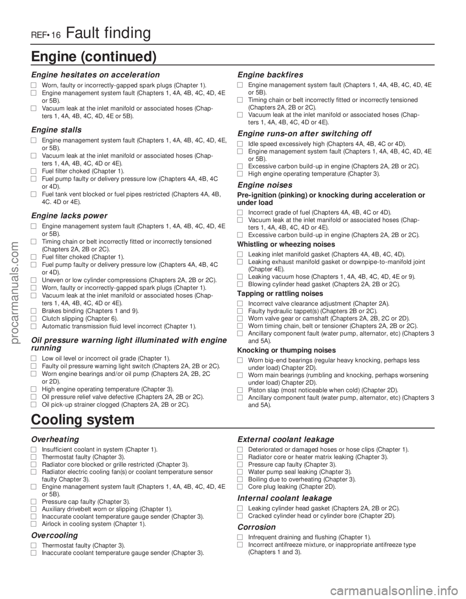
REF•16Fault finding
Cooling system
Overheating
m
mInsufficient coolant in system (Chapter 1).
m
m Thermostat faulty (Chapter 3).
m
m Radiator core blocked or grille restricted (Chapter 3).
m
m Radiator electric cooling fan(s) or coolant temperature sensor
faulty Chapter 3).
m m Engine management system fault (Chapters 1, 4A, 4B, 4C, 4D, 4E
or 5B).
m m Pressure cap faulty (Chapter 3).
m
m Auxiliary drivebelt worn or slipping (Chapter 1).
m
m Inaccurate coolant temperature gauge sender (Chapter 3).
m
m Airlock in cooling system (Chapter 1).
Overcooling
m
mThermostat faulty (Chapter 3).
m
m Inaccurate coolant temperature gauge sender (Chapter 3).
External coolant leakage
m
mDeteriorated or damaged hoses or hose clips (Chapter 1).
m
m Radiator core or heater matrix leaking (Chapter 3).
m
m Pressure cap faulty (Chapter 3).
m
m Water pump seal leaking (Chapter 3).
m
m Boiling due to overheating (Chapter 3).
m
m Core plug leaking (Chapter 2D).
Internal coolant leakage
m
mLeaking cylinder head gasket (Chapters 2A, 2B or 2C).
m
m Cracked cylinder head or cylinder bore (Chapter 2D).
Corrosion
m
mInfrequent draining and flushing (Chapter 1).
m
m Incorrect antifreeze mixture, or inappropriate antifreeze type
(Chapters 1 and 3).
Engine (continued)
Engine hesitates on acceleration
m
m Worn, faulty or incorrectly-gapped spark plugs (Chapter 1).
m
m Engine management system fault (Chapters 1, 4A, 4B, 4C, 4D, 4E
or 5B).
m m Vacuum leak at the inlet manifold or associated hoses (Chap-
ters 1, 4A, 4B, 4C, 4D, 4E or 5B).
Engine stalls
m mEngine management system fault (Chapters 1, 4A, 4B, 4C, 4D, 4E,
or 5B).
m m Vacuum leak at the inlet manifold or associated hoses (Chap-
ters 1, 4A, 4B, 4C, 4D or 4E).
m m Fuel filter choked (Chapter 1).
m
m Fuel pump faulty or delivery pressure low (Chapters 4A, 4B, 4C
or 4D).
m m Fuel tank vent blocked or fuel pipes restricted (Chapters 4A, 4B,
4C. 4D or 4E).
Engine lacks power
m mEngine management system fault (Chapters 1, 4A, 4B, 4C, 4D, 4E
or 5B).
m m Timing chain or belt incorrectly fitted or incorrectly tensioned
(Chapters 2A, 2B or 2C).
m m Fuel filter choked (Chapter 1).
m
m Fuel pump faulty or delivery pressure low (Chapters 4A, 4B, 4C
or 4D).
m m Uneven or low cylinder compressions (Chapters 2A, 2B or 2C).
m
m Worn, faulty or incorrectly-gapped spark plugs (Chapter 1).
m
m Vacuum leak at the inlet manifold or associated hoses (Chap-
ters 1, 4A, 4B, 4C, 4D or 4E).
m m Brakes binding (Chapters 1 and 9).
m
m Clutch slipping (Chapter 6).
m
m Automatic transmission fluid level incorrect (Chapter 1).
Oil pressure warning light illuminated with engine
running
m mLow oil level or incorrect oil grade (Chapter 1).
m
m Faulty oil pressure warning light switch (Chapters 2A, 2B or 2C).
m
m Worn engine bearings and/or oil pump (Chapters 2A, 2B, 2C
or 2D).
m m High engine operating temperature (Chapter 3).
m
m Oil pressure relief valve defective (Chapters 2A, 2B or 2C).
m
m Oil pick-up strainer clogged (Chapters 2A, 2B or 2C).
Engine backfires
m
mEngine management system fault (Chapters 1, 4A, 4B, 4C, 4D, 4E
or 5B).
m m Timing chain or belt incorrectly fitted or incorrectly tensioned
(Chapters 2A, 2B or 2C).
m m Vacuum leak at the inlet manifold or associated hoses (Chap-
ters 1, 4A, 4B, 4C, 4D or 4E).
Engine runs-on after switching off
m mIdle speed excessively high (Chapters 4A, 4B, 4C or 4D).
m
m Engine management system fault (Chapters 1, 4A, 4B, 4C, 4D, 4E
or 5B).
m m Excessive carbon build-up in engine (Chapters 2A, 2B or 2C).
m
m High engine operating temperature (Chapter 3).
Engine noises
Pre-ignition (pinking) or knocking during acceleration or
under load
m mIncorrect grade of fuel (Chapters 4A, 4B, 4C or 4D).
m
m Vacuum leak at the inlet manifold or associated hoses (Chap-
ters 1, 4A, 4B, 4C, 4D or 4E).
m m Excessive carbon build-up in engine (Chapters 2A, 2B or 2C).
Whistling or wheezing noises
m
mLeaking inlet manifold gasket (Chapters 4A, 4B, 4C, 4D).
m
m Leaking exhaust manifold gasket or downpipe-to-manifold joint
(Chapter 4E).
m m Leaking vacuum hose (Chapters 1, 4A, 4B, 4C, 4D, 4E or 9).
m
m Blowing cylinder head gasket (Chapters 2A, 2B or 2C).
Tapping or rattling noises
m
mIncorrect valve clearance adjustment (Chapter 2A).
m
m Faulty hydraulic tappet(s) (Chapters 2B or 2C).
m
m Worn valve gear or camshaft (Chapters 2A, 2B, 2C or 2D).
m
m Worn timing chain, belt or tensioner (Chapters 2A, 2B or 2C).
m
m Ancillary component fault (water pump, alternator, etc) (Chapters 3
and 5A).
Knocking or thumping noises
m mWorn big-end bearings (regular heavy knocking, perhaps less
under load) Chapter 2D).
m m Worn main bearings (rumbling and knocking, perhaps worsening
under load) Chapter 2D).
m m Piston slap (most noticeable when cold) (Chapter 2D).
m
m Ancillary component fault (water pump, alternator, etc) (Chapters 3
and 5A).
procarmanuals.com
http://vnx.su
Page 288 of 296
1595 Ford Fiesta Remake
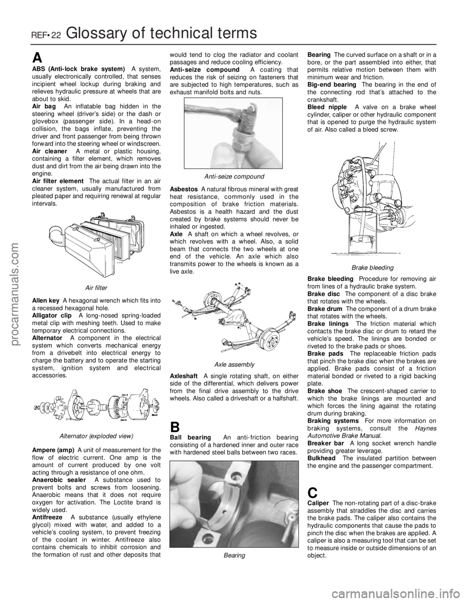
REF•22Glossary of technical terms
A
ABS (Anti-lock brake system)A system,
usually electronically controlled, that senses
incipient wheel lockup during braking and
r elieves hydraulic pressure at wheels that are
about to skid.
Air bag An inflatable bag hidden in the
steering wheel (driver’s side) or the dash or
glovebox (passenger side). In a head-on
collision, the bags inflate, preventing the
driver and front passenger from being thrown
forwar d into the steering wheel or windscreen.
Air cleaner A metal or plastic housing,
containing a filter element, which removes
dust and dirt from the air being drawn into the
engine.
Air filter element The actual filter in an air
cleaner system, usually manufactured fr om
pleated paper and requiring renewal at regular
intervals.
Allen key A hexagonal wrench which fits into
a recessed hexagonal hole.
Alligator clip A long-nosed spring-loaded
metal clip with meshing teeth. Used to make
temporary electrical connections.
Alternator A component in the electrical
system which converts mechanical energy
fr om a drivebelt into electrical energy to
char ge the battery and to operate the starting
system, ignition system and electrical
accessories.
Amper e (amp) A unit of measurement for the
flow of electric current. One amp is the
amount of current produced by one volt
acting through a resistance of one ohm.
Anaer obic sealer A substance used to
pr event bolts and screws from loosening.
Anaer obic means that it does not require
oxygen for activation. The Loctite brand is
widely used.
Antifreeze A substance (usually ethylene
glycol) mixed with water, and added to a
vehicle’ s cooling system, to prevent freezing
of the coolant in winter. Antifreeze also
contains chemicals to inhibit corrosion and
the formation of rust and other deposits that would tend to clog the radiator and coolant
passages and reduce cooling efficiency.
Anti-seize compound A coating that
r educes the risk of seizing on fasteners that
ar e subjected to high temperatures, such as
exhaust manifold bolts and nuts.
Asbestos A natural fibrous mineral with great
heat resistance, commonly used in the
composition of brake friction materials.
Asbestos is a health hazard and the dust
cr eated by brake systems should never be
inhaled or ingested.
Axle A shaft on which a wheel revolves, or
which revolves with a wheel. Also, a solid
beam that connects the two wheels at one
end of the vehicle. An axle which also
transmits power to the wheels is known as a
live axle.
Axleshaft A single rotating shaft, on either
side of the differential, which delivers power
fr om the final drive assembly to the drive
wheels. Also called a driveshaft or a halfshaft.
BBall bearing An anti-friction bearing
consisting of a hardened inner and outer race
with hardened steel balls between two races. Bearing
The curved surface on a shaft or in a
bor e, or the part assembled into either, that
permits relative motion between them with
minimum wear and friction.
Big-end bearing The bearing in the end of
the connecting rod that’s attached to the crankshaft.
Bleed nipple A valve on a brake wheel
cylinder , caliper or other hydraulic component
that is opened to purge the hydraulic system
of air. Also called a bleed screw.
Brake bleeding Procedure for removing air
fr om lines of a hydraulic brake system.
Brake disc The component of a disc brake
that rotates with the wheels.
Brake drum The component of a drum brake
that rotates with the wheels.
Brake linings The friction material which
contacts the brake disc or drum to retard the
vehicle’ s speed. The linings are bonded or
riveted to the brake pads or shoes.
Brake pads The replaceable friction pads
that pinch the brake disc when the brakes are
applied. Brake pads consist of a friction
material bonded or riveted to a rigid backing
plate.
Brake shoe The crescent-shaped carrier to
which the brake linings are mounted and
which forces the lining against the rotating drum during braking.
Braking systems For more information on
braking systems, consult the Haynes
Automotive Brake Manual .
Br eaker bar A long socket wrench handle
pr oviding greater leverage.
Bulkhead The insulated partition between
the engine and the passenger compartment.
CCaliper The non-rotating part of a disc-brake
assembly that straddles the disc and carries
the brake pads. The caliper also contains the
hydraulic components that cause the pads to
pinch the disc when the brakes are applied. A
caliper is also a measuring tool that can be set
to measure inside or outside dimensions of an
object.
Brake bleeding
Bearing
Axle assembly
Anti-seize compound
Alter nator (exploded view)
Air filter
procarmanuals.com
http://vnx.su
Page 291 of 296
1595 Ford Fiesta Remake
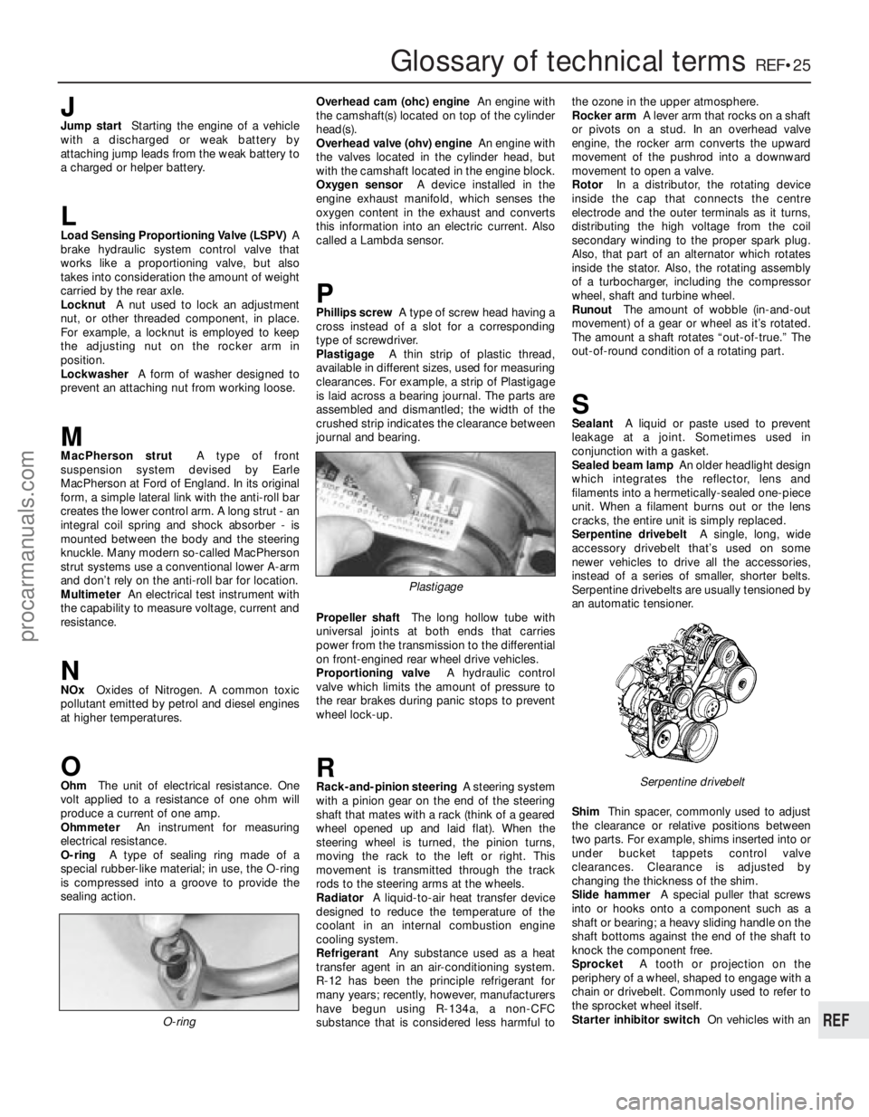
Glossary of technical termsREF•25
REF
JJump startStarting the engine of a vehicle
with a discharged or weak battery by
attaching jump leads from the weak battery to
a charged or helper battery.
LLoad Sensing Proportioning Valve (LSPV) A
brake hydraulic system control valve that
works like a proportioning valve, but also
takes into consideration the amount of weight
carried by the rear axle.
Locknut A nut used to lock an adjustment
nut, or other threaded component, in place.
For example, a locknut is employed to keep
the adjusting nut on the rocker arm in
position.
Lockwasher A form of washer designed to
pr event an attaching nut from working loose.
MMacPherson strut A type of front
suspension system devised by Earle
MacPherson at Ford of England. In its original
form, a simple lateral link with the anti-roll bar
cr eates the lower control arm. A long strut - an
integral coil spring and shock absorber - is
mounted between the body and the steering
knuckle. Many modern so-called MacPherson
strut systems use a conventional lower A-arm
and don’t rely on the anti-roll bar for location. Multimeter An electrical test instrument with
the capability to measure voltage, current and
resistance.
NNOx Oxides of Nitrogen. A common toxic
pollutant emitted by petrol and diesel engines
at higher temperatures.
OOhm The unit of electrical resistance. One
volt applied to a resistance of one ohm will
pr oduce a current of one amp.
Ohmmeter An instrument for measuring
electrical resistance.
O-ring A type of sealing ring made of a
special rubber-like material; in use, the O-ring
is compressed into a groove to provide the
sealing action. Overhead cam (ohc) engine
An engine with
the camshaft(s) located on top of the cylinder
head(s).
Overhead valve (ohv) engine An engine with
the valves located in the cylinder head, but
with the camshaft located in the engine block.
Oxygen sensor A device installed in the
engine exhaust manifold, which senses the
oxygen content in the exhaust and converts
this information into an electric current. Also
called a Lambda sensor.
PPhillips screw A type of screw head having a
cr oss instead of a slot for a corresponding
type of screwdriver.
Plastigage A thin strip of plastic thread,
available in different sizes, used for measuring clearances. For example, a strip of Plastigage
is laid across a bearing journal. The parts areassembled and dismantled; the width of the
crushed strip indicates the clearance between
jour nal and bearing.
Pr opeller shaft The long hollow tube with
universal joints at both ends that carries
power from the transmission to the differential on front-engined rear wheel drive vehicles.
Pr oportioning valve A hydraulic control
valve which limits the amount of pressure to
the rear brakes during panic stops to prevent
wheel lock-up.
RRack-and-pinion steering A steering system
with a pinion gear on the end of the steering
shaft that mates with a rack (think of a geared
wheel opened up and laid flat). When the
steering wheel is turned, the pinion turns,
moving the rack to the left or right. This
movement is transmitted through the track
r ods to the steering arms at the wheels.
Radiator A liquid-to-air heat transfer device
designed to reduce the temperature of the
coolant in an internal combustion engine
cooling system.
Refrigerant Any substance used as a heat
transfer agent in an air-conditioning system.
R-12 has been the principle refrigerant for
many years; recently, however, manufacturers
have begun using R-134a, a non-CFC
substance that is considered less harmful to the ozone in the upper atmosphere.
Rocker arm
A lever arm that rocks on a shaft
or pivots on a stud. In an overhead valve
engine, the rocker arm converts the upward
movement of the pushrod into a downward
movement to open a valve.
Rotor In a distributor, the rotating device
inside the cap that connects the centre
electr ode and the outer terminals as it turns,
distributing the high voltage from the coil
secondary winding to the proper spark plug.
Also, that part of an alternator which rotates
inside the stator. Also, the rotating assembly
of a turbocharger, including the compressor
wheel, shaft and turbine wheel.
Runout The amount of wobble (in-and-out
movement) of a gear or wheel as it’ s rotated.
The amount a shaft rotates “out-of-true.” The
out-of-r ound condition of a rotating part.
SSealant A liquid or paste used to prevent
leakage at a joint. Sometimes used in
conjunction with a gasket.
Sealed beam lamp An older headlight design
which integrates the reflector, lens and
filaments into a hermetically-sealed one-piece
unit. When a filament burns out or the lens
cracks, the entire unit is simply replaced.
Serpentine drivebelt A single, long, wide
accessory drivebelt that’s used on some
newer vehicles to drive all the accessories,
instead of a series of smaller, shorter belts.
Serpentine drivebelts are usually tensioned by
an automatic tensioner.
Shim Thin spacer, commonly used to adjust
the clearance or relative positions between
two parts. For example, shims inserted into or
under bucket tappets control valve
clearances. Clearance is adjusted by
changing the thickness of the shim.
Slide hammer A special puller that screws
into or hooks onto a component such as a
shaft or bearing; a heavy sliding handle on the
shaft bottoms against the end of the shaft to
knock the component free.
Sprocket A tooth or projection on the
periphery of a wheel, shaped to engage with a
chain or drivebelt. Commonly used to refer to
the sprocket wheel itself.
Starter inhibitor switch On vehicles with an
O-ring
Serpentine drivebelt
Plastigage
procarmanuals.com
http://vnx.su