1988 PONTIAC FIERO brake light
[x] Cancel search: brake lightPage 1454 of 1825
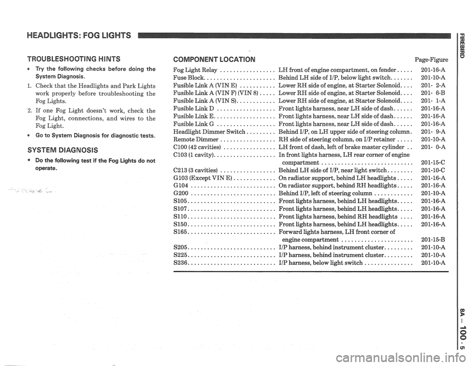
HEADLIGHTS: FOG LIGHTS
TROUBLESHOOTING HINTS
r Try the following checks before doing the
System Diagnosis
.
1 . Check that the Headlights and Park Lights
work properly before troubleshooting the
Fog Lights
.
2 . If one Fog Light doesn't work, check the
Fog Light. connections. and wires to the
Fog Light
.
Go to System Diagnosis for diagnostic tests .
SYSTEM DIAGNOSIS
Do the following test if the
operate
.
-., U .
Fog Lights do not
COMPONENT LOCATION Page-Figure
Fog Light Relay
................. LH front of engine compartment. on fender .....
Fuse Block ...................... Behind LH side of IIP. below light switch .......
Fusible Link A (VIN E) ........... Lower RN side of engine. at Starter Solenoid ....
Fusible Link A (VIN F) (VIN 8) ..... Lower RH side of engine. at Starter Solenoid ....
Fusible Link A (VIN S) ............ Lower RH side of engine. at Starter Solenoid ....
Fusible Link D .................. Front lights harness. near kH side of dash ......
Fusible Link E ................... Front lights harness. near LH side of dash ......
Fusible Link 6 .................. Front lights harness. near LN side of dash ......
......... . er Switch Behind IIP. on EN upper side
of steering column
Remote
Dimmer ................. RH side of steering column. on IIP retainer ..... .
C100 (42 cavities) ................ LH front of dash. left of brake master cylinder ..
C103 (1 cavity) ................... In front lights harness. LH rear corner of engine
compartment
............................
C213 (3 cavities) ................. Behind LH side of IIP. near Light switch ........
6103 (Except VIN E) ............. On radiator support. behind LR headlights .....
6104 .......................... On radiator support. behind RN headlights .....
6200 .......................... Behind IIP. left of steering column ............
S105 ........................... Front lights harness. behind LH headlights .....
S107 ........................... Front lights harness. behind LH headlights .....
S110 ........................... Front lights harness. behind RH headlights ....
S150 ........................... Front lights harness. behind LH headlights .....
S165 ........................... Forward lights harness. LH front corner of
engine compartment
......................
S205 ........................... I/P harness. behind instrument cluster .........
S225 ........................... I/P harness. behind instrument cluster .........
S236 ........................... IIP harness. below light switch ...............
Page 1458 of 1825
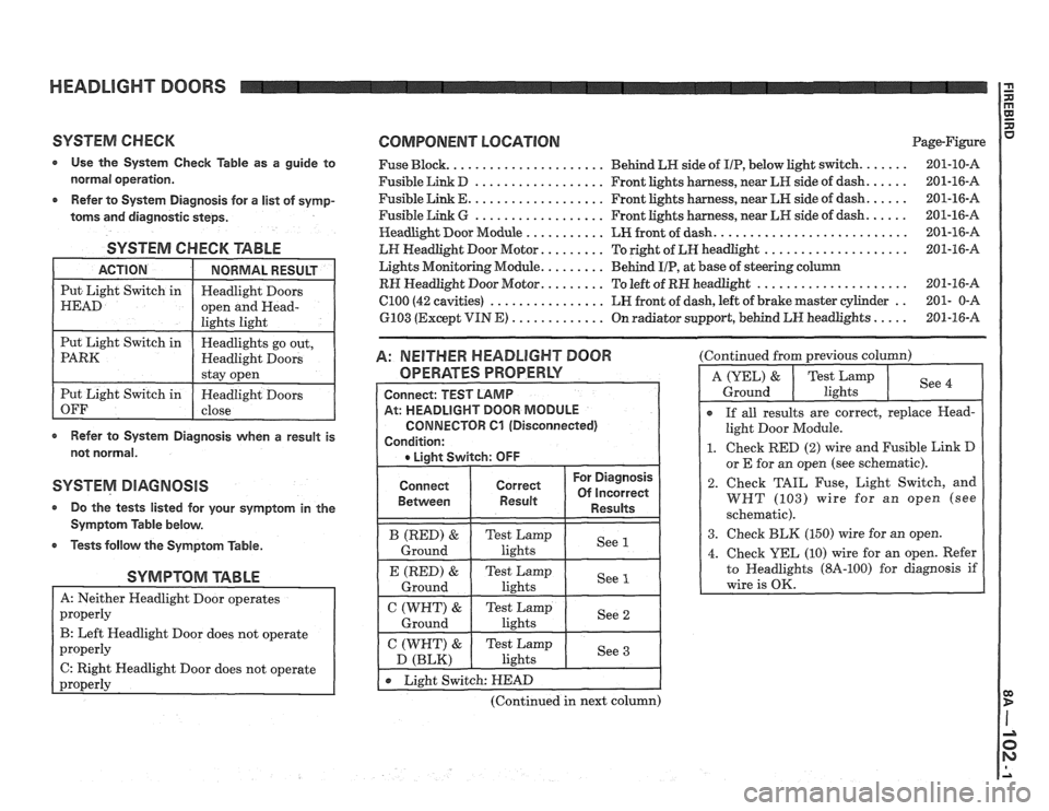
HEADLIGHT DOORS
SYSTEM CHECK COMPONENT LOCATION Page-Figure
Use the System Check Table as a guide to Fuse Block. ..................... Behind LN side of IIP, below light switch. ...... 201-10-A
normal operation. Fusible Link D .................. Front lights harness, near LR side of dash. ..... 201-16-A
..... .................. Refer to System Diagnosis for a list of symp- Fusible Link E. Front lights harness, near LN side of dash. 201-16-A
..... .................. toms and
diagnostic steps. Fusible Link G Front lights harness, near LH side of dash. 201-16-A
.......................... Headlight
Door Module ........... LH front of dash. 201-16-A
SYSTEM CHECK TABLE
Refer to System Diagnosis when a result is
not normal.
SYSTEM DIAGNOSIS
a Do the tests listed for your symptom in the
Symptom Table below.
Tests follow the Symptom Table.
SYMPTOM TABLE
B: Left Headlight Door does not operate
C: Right Headlight Door does not operate
-
LH Headlight Door Motor. ........ To right of LH headlight .................... 201-16-A
Lights Monitoring Module.
........ Behind UP, at base of steering column
RH Headlight Door Motor. ........ To left of RN headlight ..................... 201-16-A
C100 (42 cavities) ................ LH front of dash, left of brake master cylinder .. 201- 0-A
6103 (Except VIN
E) ............. On radiator support, behind LN headlights ..... 201-16-A
A: NEITHER HEADLIGHT DOOR
OPERATES PROPERLY
Connect
Between
(Continued in next column) (Continued
from previous column)
I
r If all results are correct, replace Head-
light Door Module.
1. Check RED (2) wire and Fusible Link D
or E for an owen (see schematic).
2. Check TAIL Fuse, Light Switch, and
WHT (103) wire for an open (see
schematic).
3. Check BLK (150) wire for an open.
Page 1462 of 1825
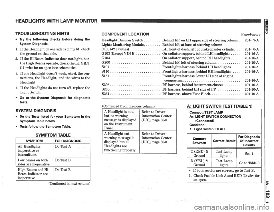
HEADLIGHTS WITH LAMP MONITOR
TROUBLESHOOTING HINTS
r Try the following checks before doing the
System Diagnosis.
1. If the Headlight on one side is dimly lit, check
the ground on that side.
2. If the Hi Beam Indicator does not light, but
the High Beams operate, check the LT GRN
(11) wire for an open (see schematic).
3. If one Headlight doesn't work, check the con-
nections, the Headlight, and the wires to the
Headlight.
4. If the Headlights do not turn off, replace the
Light Switch.
Go to the System Diagnosis for diagnostic
tests.
SYSTEM DIAGNOSIS
0 Do the Tests listed for your Symptom in the
Symptom Table below.
@ Tests follow the Symptom Table.
SYMPTOM TABLE
I SYMPTOM I FOR DIAGNOSIS I
All Headlights
inoperative or
intermittent Do
Test A
Beam Indicator are
(Continued in next column)
COMPONENT LOCATION Page-Figure
Headlight Dimmer Switch.
........ Behind IIP, on LH upper side of steering column. 201-
9-A
Lights Monitoring Module.
........ Behind IIP, at base of steering column
.. el00 (42 cavities) ................ LH front of dash, left of brake master cylinder
201- 0-A
.... 6103 (Except VIN E) ............. On radiator support, behind LH headlights.
201-16-A
.... 6104 .......................... On radiator support, behind RH headlights.
201-16-A
............ 6200 .......................... Behind IIP, left of steering column
201-10-A
.... S107. .......................... Front lights harness, behind LH headlights.
201-16-A
.... S110. .......................... Front lights harness, behind RH headlights
201-16-A
S151. .......................... Front lights harness, lower LH side of engine
compartment
............................ 201-16-A
........ S205. .......................... IIP harness, behind instrument cluster. 201-10-A
............ S230. .......................... IIP harness, behind LH side of IIP 201-10-A
............... S231. .......................... IIP harness, above Fuse Block. 201-10-A
(Continued from previous column)
A Headlight is out,
but no warning
message is displayed
on the Instrument
Panel
A: LIGHT SWITCH TEST (TABLE 1)
At: LIGHT SWITCH CONNECTOR
(Connected)
Condition: Light Switch: HEAD
Refer to Driver
Information Center
(DIC), page 86-0
A Headlight out
warning message is
displayed but all
Headlights are
functioning properly For Diagnosis
Connect
Correct Result Of Incorrect
1 Between 1 1 Results 1
Refer to Driver
Information Center
(DIG), page 86-0
I Ground (RED) I Te;ik,",mp I see 1 I
If both results are correct, go to Test B.
1. Check Fusible Link A and RED (2) wire for
an open.
D (YEL) &
Ground Test Lamp
lights Go to able
Page 1466 of 1825
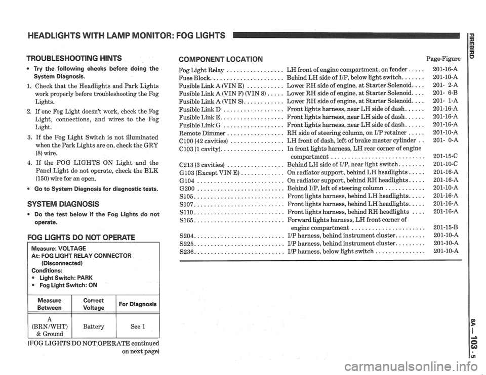
HEADLIGHTS WlTH LAMP MONITOR: FOG LIGHTS
TROUBLESHOOTING MINTS
0 Try the following checks before doing the
System Diagnosis.
1. Check that the Headlights and Park Lights
work properly before troubleshooting the Fog
Lights.
2. If one Fog Light doesn't work, check the Fog
Light, connections, and wires to the Fog
Light.
3. If the Fog Light Switch is not illu
when the Park Lights are on, check the
GRU
(8) wire.
4.
If the FOG LIGHTS ON Light and the
Panel Light do not operate, check the BLK
(150) wire for an open.
Go to System Diagnosis for diagnostic tests.
SYSTEM DIAGNOSIS
Do the test below if the Fog Lights do not
operate.
FOG LIGHTS DO NClT OPEWTE
Measure: VOLTAGE
At: FOG
LIGHT RELAY CONNECTOR
(Disconnected)
Conditions:
r Light Switch: PARK
Fog Light Switch:
ON
Measure Correct
For Diagnosis
Belvveen
COMPONENT LOCATION Page-Figure
................. Fog Light Relay LH front
of engine compartment, on fender. .... 201-16-A
..................... Fuse Block. Behind
LH side of IIP, below light switch. ...... 201-10-A
Fusible Link A (VIN
E) ........... Lower RN side of engine, at Starter Solenoid. ... 201- 2-A
Fusible Link A (VIN F) (VIN 8)
..... Lower RH side of engine, at Starter Solenoid. ... 201- 6-B
Fusible Link A (VIN S). ........... Lower RH side of engine, at Starter Solenoid. ... 201- 1-A
.................. Fusible Link D Front lights harness, near LH side of dash. ..... 201-16-A
.................. Fusible Link E. Front lights harness, near LH side of dash. ..... 201-16-A
.................. Fusible Link G Front
lights harness, near LK side of dash. ..... 201-16-A
................. Remote Dimmer RH side of steering column, on IIP retainer ..... 201-10-A
................ el00 (42 cavities) LH front
of dash, left of brake master cylinder .. 201- 0-A
.................. 6103 (1 cavity). In
front lights harness, LH rear corner of engine
.......................... compartment.. 201-15-C
................. 6213 (3 cavities) Behind LH side
of IIP, near light switch. ....... 201-10-C
6103 (Except VIN E) ............. On radiator support, behind LK headlights. .... 201-16-A
.......................... 6104 On radiator support, behind RH headlights. .... 201-16-A
.......................... ............ 6200 Behind IIP, left of steering column 201-10-A
.......................... S105. Front lights harness, behind LH headlights. .... 201-16-A
.......................... S107. Front lights harness, behind LH headlights. .... 201-16-A
.......................... S110. Front lights harness, behind RH headlights .... 201-16-A
S165. .......................... Forward lights harness, LH front comer of
...................... engine compartment 201-15-B
.......................... S204. I/P harness, behind instrument cluster. ........ 201-10-A
.......................... S225. I/P harness, behind instrument cluster. ........ 201-10-A
.......................... ............... S236. IIP harness, below light switch 201-10-A
(BRNIWNT)
& Ground
(FOG LIGHTS DO
NOT OPERATE continued
on next page)
Battery
See
1
Page 1471 of 1825
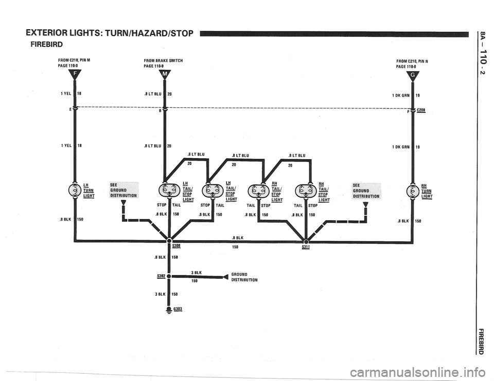
EXTERIOR LIGHTS: TURNIHAZARDISTOP I
FROM C210, PIN M
PAGE 110-0 FROM BRAKE SWITCH PAGE 110-0 FROM C210, PIN N PAGE 110-0
Page 1474 of 1825
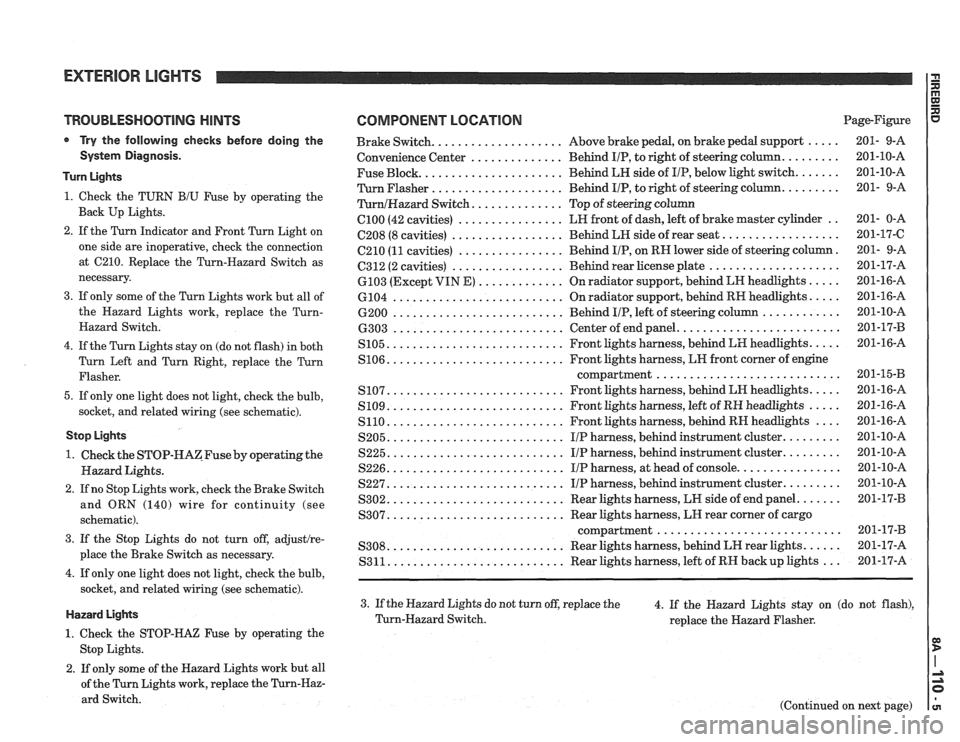
TROUBLESHOOTING HINTS
Try the following checks before doing the
System Diagnosis.
Turn Lights
1. Check the TURN B/U Fuse by operating the
Back Up Lights.
2. If the Turn Indicator and Front Turn Light on
one side are inoperative, check the connection
at
C210. Replace the Turn-Hazard Switch as
necessary.
3. If only some of the Turn Lights work but all of
the Hazard Lights work, replace the
Turn-
Hazard Switch.
4. If the Turn Lights stay on (do not flash) in both
Turn Left and Turn Right, replace the Turn
Flasher.
5. If only one light does not light, check the bulb,
socket, and related wiring (see schematic).
Stop Lights
1. Check the STOP-HAZFuse by operating the
Hazard Lights.
2. If no Stop Lights work, check the Brake Switch
and ORN (140) wire for continuity (see
schematic).
3. If the Stop Lights do not turn off, adjustlre-
place the Brake Switch as necessary.
4. If only one light does not light, check the bulb,
socket, and related wiring (see schematic).
Hazard Lights
1. Check the STOP-HAZ Fuse by operating the
Stop Lights.
2. If only some of the Hazard Lights work but all
of the Turn Lights work, replace the
Turn-Haz-
ard Switch.
COMPONENT LOCATION Page-Figure
................... ..... Brake Switch. Above
brake pedal, on brake pedal support 201- 9-A
.............. ........ Convenience
Center Behind IIP, to right of steering column. 201-10-A
Fuse Block.
..................... Behind LH side of IIP, below light switch. ...... 201-10-A
Turn Flasher
.................... Behind IIP, to right of steering column. ........ 201- 9-A
............. TurnlHazard Switch. Top of steering column
C100 (42 cavities) ................ LH front of dash, left of brake master cylinder .. 201- 0-A
................. ................. C208 (8 cavities) Behind LH side of rear seat. 201-17-C
C210
(11 cavities) ................ Behind IIP, on RN lower side of steering column. 201- 9-A
................. .................... 6312 (2 cavities) Behind rear license plate 201-17-A
............. ..... 6103 (Except VIN E) On radiator support, behind LN headlights 201-16-A
.......................... .... 6104
On radiator support, behind RH headlights. 201-16-A
.......................... ............ 6200 Behind IIP, left of steering column 201-10-A
........................ .......................... 6303 Center of end panel. 201-17-B
.......................... .... S105. Front lights harness, behind LH headlights. 201-16-A
.......................... S106. Front lights harness, LN front corner of engine
compartment..
.......................... 201-1543
.......................... .... S107. Front lights harness, behind LH headlights. 201-16-A
.......................... ..... S109. Front lights harness, left of RH headlights 201-16-A
S110. .......................... Front lights harness, behind RH headlights .... 201-16-A
S205. .......................... IIP harness, behind instrument cluster. ........ 201-10-A
S225. .......................... IIP harness, behind instrument cluster. ........ 201-10-A
S226. .......................... IIP harness, at head of console. ............... 201-10-A
S227. .......................... IIP harness, behind instrument cluster. ........ 201-10-A
S302. .......................... Rear lights harness, LW side of end panel. ...... 201-17-B
.......................... S307. Rear lights harness, LH rear corner of cargo
compartment..
.......................... 201-17-B
.......................... ..... S308. Rear lights harness, behind LH rear lights. 201-17-A
S311. .......................... Rear lights harness, left of RH backup lights ... 201-17-A
3. If the Hazard Lights do not turn off, replace the
4. If the Hazard Lights stay on (do not flash),
Turn-Hazard Switch.
replace the Hazard Flasher.
(Continued on next page)
Page 1475 of 1825
EXTERIOR LlGHTS
(Continued from previous page)
Park/MarkerflaIl/License UgMs
1. If the Park, Marker and Tail Lights do not
work, cheek the Tail Fuse, Light Switch, and
BRN (9) wires for continuity (see schematic).
2. If the Front Marker and the Park Lights dd not
work, check the connection at 6100 and re-
lated wiring (see schematic).
3. If the Park Lights do not turn off, replace the
Light Switch.
s Go to System Diagnosis for diagnostic tests.
@ Do the tests listed for your symptom in the
Symptom
Able bezaw.
@ Tests follow the Symptom Table.
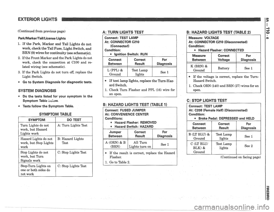
SYMPTOM arABhE
A: TURN LIGHTS TEST
SYMPTOM
Turn Lights do not
work, but Hazard
Lights work
Hazard Lights do not
work, but Stop Lights
work
Stop Lights do not
work, but Turn
Signals work
Stop-Turn Lights on
one or both sides do
not work
B: HAZARD LIGHTS TEST (TABLE 2)
DO TEST
A: Turn Lights Test
B: Hazard Lights
Test
6: Stop Lights Test
6: Stop Lights Test
Connect: TEST LAMP
At: CONNECTOR C210
(Connected)
Condition:
Ignition Switch: RUN
o If the result is correct, replace the Hazard
Flasher.
1. Go to Table 2.
B: HAZARD LIGHTS TEST (TABLE 1)
Connect: FUSED JUMPER
At: CONVENIENCE
CENTER
Conditions:
r Hazard Flasher: REMOVED
Hazard Switch:
HAZARD
Measure: VOLTAGE
At: CONNECTOR 621 0 (Disconneded)
Condition:
Hazard Flasher: CONNECTED
For
Diagnosis
See 1
Connect
Between
L (PPL) &
Ground
I Measure ( Correct ( For
e If test lamp lights, replace the
ard Switch.
1. Check Turn Flasher and PPE (16) wire for
an open.
Correct
Result
Test Lamp
lights
For
Diagnosis
See 1
Jumper
Between
A (QRN) & B
(BRN)
Between I Voltage I Diagnosis
Correct Result
All Turn
Lights turn on
( If the voltage is correct, replace the Turn- I
(BRN) &
Ground
Hazard Switch.
1. Check ORN (140) and BRN (27) wires for an
open.
6: STOP LIGHTS TEST
At: 6208 (Fernale Half) (Disconnected)
Condition:
Brake Pedal: DEPRESSED and HELD
Battery See 1
Connect
Behvveen
I CEKyy 1 Test Lamp
lights I See 2 I
B (LT BLU) &
Ground
I Ground I I I
Correct
Result
(Continued on facing page)
For
Diagnosis
Test Lamp
lights See 1
Page 1476 of 1825
(Continued from facing page)
@ If the results are correct for the Trans AM,
check WHT (17) wire to the Turn-Hazard
Switch. Replace the Turn-Hazard Switch if
the wiring is OK and the Rear Turn Lights
light; for the Firebird, check the bulb,
socket, and related wiring (see schematic).
1. Check the Brake Switch,
LT BLU (20) and
ORN (140) wires for continuity. Repair1
replace as necessary.
2. Check the Brake Switch, ORN (140) and LT
BLU (820) wires for continuity.
Repairlre-
place as necessary.
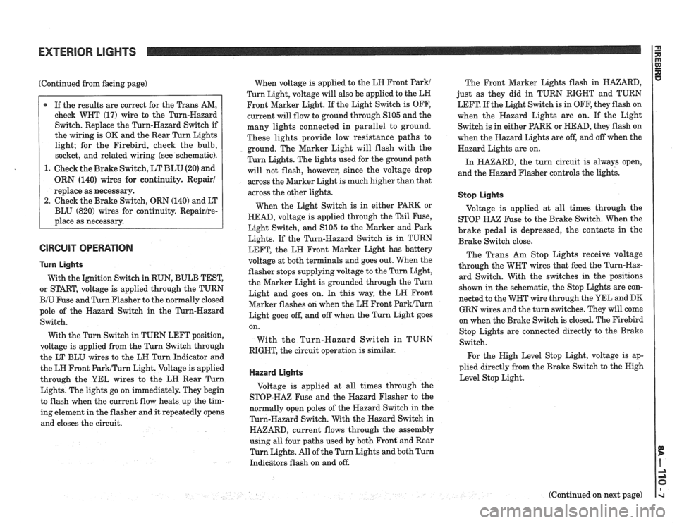
GlRGUlT OPERATION
Turn Lights
With the Ignition Switch in RUN, BULB TEST,
or START, voltage is applied through the TURN
BIU Fuse and Turn Flasher to the normally closed
pole of the Hazard Switch in the Turn-Hazard
Switch.
With the Turn Switch in TURN LEFT position,
voltage is applied from the Turn Switch through
the LT BLU wires to the LH Turn Indicator and
the LH Front
ParWTurn Light. Voltage is applied
through the YEL wires to the LH Rear Turn
Lights. The lights go on immediately. They begin
to flash when the current flow heats up the tim-
ing element in the flasher and it repeatedly opens
and closes the circuit. When
voltage is applied to the LH Front
Park1
Turn Light, voltage will also be applied to the LH
Front Marker Light. If the Light Switch is OFF,
current will flow to ground through
S105 and the
many lights connected in parallel to ground.
These lights provide low resistance paths to
ground. The Marker Light will flash with the
Turn Lights. The lights used for the ground path
will not flash, however, since the voltage drop
across the Marker Light is much higher than that
across the other lights.
When the Light Switch is in either PARK or
HEAD, voltage is applied through the Tail Fuse,
Light Switch, and
S105 to the Marker and Park
Lights. If the Turn-Hazard Switch is in TURN
LEFT, the LH Front Marker Light has battery
voltage at both terminals and goes out. When the
flasher stops supplying voltage to the Turn Light,
the Marker Light is grounded through the Turn
Light and goes on. In this way, the LN Front
Marker flashes on when the LH Front
ParkITurn
Light goes off, and off when the Turn Light goes The
Front Marker Lights flash in HAZARD,
just as they did in TURN RIGHT and TURN
LEFT. If the Light Switch is in OFF, they flash on
when the Hazard Lights are on. If the Light
Switch is in either PARK or HEAD, they flash on
when the Hazard Lights are off, and off when the
Hazard Lights are on.
In HAZARD, the turn circuit is always open,
and the Hazard Flasher controls the lights.
Stop Lights
Voltage is applied at all times through the
STOP
HA% Fuse to the Brake Switch. When the
brake pedal is depressed, the contacts in the
Brake Switch close.
The Trans Am Stop Lights receive voltage
through the WHT wires that feed the Turn-Haz-
ard Switch. With the switches in the positions
shown in the schematic, the Stop Lights are con-
nected to the WHT wire through the YEL and DK
GRN wires and the turn switches. They will come
on when the Brake Switch is closed. The
Firebird on.
With
RIGHT, Stop
Lights are connected directly to the Brake
the Turn-Hazard Switch in TURN
Switch.
the circuit operation is similar.
For the High Level Stop Light, voltage is ap-
plied directly from the Brake Switch to the Nigh
Hazard Lights Level Stop Light.
Voltage is applied at all times through the
STOP-HAZ Fuse and the Hazard Flasher to the
normally open poles of the Hazard Switch in the
Turn-Hazard Switch. With the Hazard Switch in
HAZARD, current flows through the assembly
using all four paths used by both Front and Rear
Turn Lights. All of the Turn Lights and both Turn
Indicators flash on and off.
(Continued on next page)