1988 PONTIAC FIERO brake light
[x] Cancel search: brake lightPage 991 of 1825

700-R4-2 HYDRAULIC DIAGNOSIS
R - Reverse allows the vehicle to be operated in
a rearward direction.
N - Neutral allows the engine to be started and
operated without driving the vehicle. If necessary this
position may be selected if the engine must be restarted
with the vehicle moving.
D - Overdrive is used for all normal driving
conditions. It provides four gear ratios plus converter
clutch operation. Downshifts are available for safe
passing by depressing the accelerator.
D - Drive position is used for city traffic, hilly
terrain, and trailer towing. It provides three gear
ranges. Again, downshifts are available by depressing
the accelerator.
2 - Manual second is used to provide acceleration
and engine braking. This range may be selected at any
vehicle speed.
1 - Manual Lo is used to provide maximum
engine
brlking. This range may also be selected at any
vehicle speed.
DIAGNOSIS INFORMATION
ROAD TEST PROCEDURE
e Perform the road test following the sequence
given
e MPH (KPH) shift points will vary with actual
throttle position and driver habits
e Compare the results of the test with speed shift
chart information. Use these results with the
diagnosis information contained in this
Automatic Transmission Hydraulic Diagnosis
Section to evaluate the transmission.
e This test should only be performed when traffic
and road conditions permit
e Observe all traffic safety regulations
Drive and Reverse Engagement Shift Check
1. Start engine
2. Depress brake pedal
3. Move gear selector:
- "Park" (P) to "Reverse" (R)
- "Reverse" (R) to "Neutral"
(N) to "Drive" (D)
Gear selections should be immediate and
not harsh.
Upshifts and Torque Converter Clutch (TCC)
Apply (Figure
2)
With gear selector in "Overdrive" (D)
1. Accelerate using a steady increasing throttle
pressure
2. Note the shift speed point gear engagements for:
- 2nd gear
- 3rd gear
- Overdrive
3. Note the speed shift point for TCC apply. This
should occur while in third gear or overdrive. If
the apply is not noticed, refer to the Preliminary
Torque Converter Clutch Diagnosis information
contained in this section of the Service Manual.
Important
The torque converter clutch will not engage if
engine coolant has not reached a minimum
operating temperature of approximately 54°C
(1 30°F).
Part Throttle Downshift
At vehicle speeds of 40-55 MPH (64-88
KPH) quickly depressed the accelerator to
a half open position and observe:
- TCC releases
- Transmission downshift to 3rd gear
immediately
Full Throttle (Detent) Downshift
At vehicle speeds of 48-55 MPH (77-88
KPH) quickly depress the accelerator to a
wide open position and observe:
- TCC releases
- Transmission downshifts to 2nd gear
immediately
Manual Downshift
1. At vehicle speeds of 40-55 MPH (64 to 88 KPH)
release the accelerator pedal while moving the
gear selector to "Third" gear (D) and observe:
- TCC release
- Transmission downshift to 3rd gear should
be immediate
- Engine should slow vehicle down
2. Move gear selector to "Overdrive" and accelerate
to 40-45 MPH (64-72 KPH). Release the
accelerator pedal while moving the gear selector
to "Second" gear (2) and observe.
- TCC release
- Downshift to second gear should be
immediate
- Engine should slow vehicle down
3. Move gear selector to "Overdrive" (D) and
accelerate to 25 MPH (40 KPH). Release the
accelerator pedal while moving the gear selector
to "First" gear (1) and observe:
- TCC release
- Transmission downshift to 1st gear should
be immediate
- Engine should slow vehicle down
Coastdown Downshift
1. With the gear selector in "Overdrive" (D)
accelerate to 4th gear with TCC applied.
2. Release the accelerator pedal and lightly apply
the brakes to observe:
- TCC release
- Shift points for downshifts.
Manual Gear Range Selection
MANUAL THIRD (D)
1. With vehicle stopped, place gear selector in
"Third" (D) and accelerate to observe:
Page 1050 of 1825
TORQUE CONVERTER CLUTCH (TCC)
DIAGNOSIS
To properly diagnose the Torque Converter
Clutch (TCC) system, perform all electrical
testing first and then the hydraulic testing. Refer
to the Torque Converter Section
6E2-C8 for
additional information.
The TCC is applied by fluid pressure which is
controlled by a solenoid located inside the Automatic
Transmission assembly. The solenoid is energized or
released by making or breaking an electrical circuit
through a combination of switches and sensors.
TCC Electrical Diagnosis
e For electrical diagnosis of TCC, refer to the
specific vehicle section in Section
8A, Electrical
Diagnosis.
e For diagnosis of emission control related
components of TCC, Refer to the specific section
of
6E, Driveability and Emissions.
e For the diagnosis of TCC Hydraulic Controls,
refer to the Procedure and Wiring Diagrams
provided in this section.
Functional Check Procedure
rn Inspect
1. Install a tachometer
2. Operate the vehicle until proper operating
temperature is reached
3. Drive vehicle at 50-55 mph (80-88 Km/h) with
light throttle (road load)
4. Maintaining throttle lightly touch the brake
pedal and check for a slight bump when the TCC
releases and a slight increase in engine RPM.
5. Release the brake, slowly accelerate and check for
a re-apply of the converter clutch and a slight
decrease in engine RPM.
Preliminary Checking Procedure
The purpose of the preliminary checking
procedure is to isolate external (electrical) problems
from internal (electrical or mechanical) ones.
Important
e Use only a scale type ohmmeter. High impedance
type ohmmeters and those with a digital readout
will not work.
e An ALCL scanner may be used to verify the
electrical circuit. Remember, a completed circuit
does not indicate that the solenoid will apply.
e Do not bench test using an automotive type
battery. Accidentally crossed wires will damage
the internal diodes of the TCC solenoid.
HYDRAULIC DIAGNOSIS 700-R4-61
External Controls
rn Inspect
e Connect voltmeter between transmission
connector and ground.
e Turn key "ON"
e If 0 or low voltage is found, refer to Sections 6E
and 8A for electrical diagnosis.
e If 12 volts are present at the connector, refer to
the TCC hydraulic diagnosis.
TORQUE CONVERTER EVALUATION
Torque Converter Stator
The Torque Converter Stator roller clutch can
have one of two different type malfunctions:
A. Stator Assembly freewheels in both
directions.
B. Stator Assembly remains locked up at all
times.
Condition A-Poor Acceleration Low Speed
The vehicle tends to have poor acceleration from
a standstill. At speeds above 30-35 mph (50-55
km/h),
the car may act normal. If poor acceleration is noted,
it should first be determined that the exhaust system
is not blocked, the engine timing is correct and the
transmission is in first
(1st) gear when starting out.
If the engine freely accelerates to high
r.p.m. in
"NEUTRAL" (N), it can be assumed that the engine
and exhaust system are normal. Checking for poor
performance in "Drive" and Reverse will help
determine if the stator is freewheeling at all times.
Condition B-Poor Acceleration High Speed
Engine r.p.m. and car speed limited or restricted
at high speeds. Performance when accelerating from a
standstill is normal. Engine may over-heat. Visual
examination of the converter may reveal a blue color
from over-heating.
If the converter has been removed, the stator
roller clutch can be checked by inserting a finger into
the splined inner race of the roller clutch and trying to
turn the race in both directions. The inner race should
turn freely clockwise, but not turn or be very difficult
to turn counterclockwise.
The Converter Should Be Replaced If:
e Leaks externally, such as at the hub weld area.
e Converter has an imbalance which cannot be
corrected. (Refer to Converter Vibration Test
Procedure).
e Converter is contaminated with engine coolant
containing antifreeze.
The Converter Should Not Be Replaced If:
e The oil has an odor, is discolored, and there is no
evidence of metal or clutch facing particles.
e The threads in one or more of the three converter
bolt holes are damaged.
- Correct with thread insert. (Refer to Section
6A).
Page 1159 of 1825
7C-2 CLUTCH
PRELIMINARY CHECKS
Before attempting to repair the clutch,
transmission or related hydraulic components for any
reason other than
an obvious failure, the problem and
probable cause should be identified.
A large percentage
of clutch and manual transmission
problenls are
manifested by shifting difficulties such as high shift
effort, gear clash and grinding or transmission
blockout. When any of these problems occur, a careful
analysis of these difficulties should be accomplished
and the following checks and adjustments performed
in the presented sequence before removing the clutch
or transmission for repairs.
Before
removal of the clutch hydraulic system,
verify the malfunction by renloving the clutch housing
dust shield and
measure the travel of the clutch slave
cylinder push rod. With clutch pedal pushed fully to
the floor, the
slave cylinder push rod should extend
14.53mm (0.57 inch) minimum against the clutch
release lever. Do
not replace the hydraulic system if
push rod travel exceeds this distance.
If slave cylinder does not meet the travel require-
ments, check the reservoir fluid level. The slave cylinder
must be in place when checking the fluid level. The proper
level is indicated by a step on the reservoir. Fill to the
specified level with
GM Delco Supreme No. 11 Brake
Fluid or an equivalent fluid that meets DOT
3 specifica-
tions. Do not overfill. The upper portion of the reservoir
must accept fluid that is displaced from the slave cylinder
as the clutch wears.
NOTICE: Carefully clean the top and sides of the
reservoir before opening to prevent contamination of
the system with dirt, water or other foreign material.
Remove the reservoir diaphragm before adding fluid.
Carefully replace the diaphragm, cover gasket and
cover after filling.
If the reservoir requires any fluid, check the
hydraulic system components for leakage. Remove the
rubber boots from the cylinder and check for leakage
past the pistons. A slight wetting of the surfaces is
acceptable. Replace the system, if excessive leakage is
evident.
BLEEDING CLUTCH SYSTEM
allowed to fall so low that air has been drawn into the
master cylinder.
NOTICE: Never, under any circumstances, use
fluid which has been bled from a system to fill the
reservoir as it may be aerated, have too much
moisture content and possibly be contaminated.
Clean dirt and grease from the cap to ensure no
foreign substances enter the system.
Remove cap and diaphragm and
fill reservoir to
the top with approved brake fluid only. (Brake
fluid must be certified to DOT 3 specifications).
Fully loosen bleed screw which is in the slave
cylinder body next to the inlet connection.
Fluid will now begin to move from the master
cylinder down the tube to the slave. It is
important that for efficient gravity
fill, the
reservoir must be kept full at all times.
It will be noticeable at this point that bubbles will
appear at the bleed screw outlet. This means that
air is being expelled. When the slave is full, a
steady stream of fluid will come from the slave
outlet. At this point tighten bleed screw to a
torque of 2
N .m.
Assemble diaphragm and cap to the reservoir,
fluid in reservoir should be level with step.
Exert a light load (approximately 20 lbs.) to the
slave cylinder piston by pushing release lever
towards the cylinder and loosen bleed screw.
Maintain a constant light load, fluid and any air
that is left will be expelled through the bleed port.
Tighten bleed screw when a steady flow of fluid
and no air is being expelled.
Renew fluid level in reservoir, assemble
diaphragm and cap. If necessary, repeat Steps
7
and 8.
Exert light load to release lever as in Step 7 (do
not open bleed screw), piston in slave will move
slowly down bore. Repeat 2-3 times, fluid
n~oven~ent will force any air left in the system into
the reservoir.
The hydraulic system should now be fully bled
and should release the clutch. Check vehicle by
starting, pushing clutch pedal to the floor and
selecting reverse gear. There should be no grating
of gears, if there is, the hydraulic system could
still contain air. If this is the case, repeat bleed
The process of removing air from the
line and procedure.
cylinders is known as "bleeding" and is necessary Check push rod travel at the
slave cylinder to insure
whenever the level of fluid in the reservoir has been the minimum travel
of
14.53mm (0.57 inch) for V-8
and 1 lrnm (0.43 inch) for V-6.
Page 1163 of 1825
7C-6 CLUTCH
6. Clutch master cylinder push rod to clutch pedal.
7. Install brake switch.
8. Install hush panel.
9. Install steering column trim cover.
10. Install clutch reservoir to bracket.
1 1. Hoist vehicle.
12. Pilot slave cylinder into clutch fork.
NOTICE: With a new system, the slave cylinder
contains a shipping strap that pre-positions the
push rod for installation, and also provides a
bearing insert.
Follojving installation of the slave
cylinder, the first actuation of the clutch pedal will
break the shipping strap and give
normal system
operation.
13. Install slave cylinder and heat shield to bell
housing.
14.
Lojver vehicle.
15. Connect negative battery cable.
CLUTCH ASSEMBLY
Removal
1. Remove the transmission as outlined in
transmission section.
2. Remove the slave cylinder heat shield and slave
cylinder
from flywheel housing.
3. Reniove the flywheel housing.
4. Slide clutch fork from ball stud and remove fork
from dust boot. Ball stud is threaded into clutch
housing and is easily replaced, if necessary.
5. Install Tool 5-33169 to support the clutch
assen~bly during removal. Look for mark or white
painted letter on clutch cover and
"X" mark on
flywheel. If
"Xu or letter is not evident, mark
flywheel and clutch cover for indexing purposes
during installation.
6. Loosen clutch-to-flywheel attaching bolts evenly
1 turn at a time until spring pressure is released.
7. Remove clutch and pressure plate assembly.
lnspection
Inspect the flywheel for cracks, heat checking or
other defects. Replace or repair as required.
Installation
Pressure plate and flywheel face, (They should be
free of oil, grease, metal deposits or burned spots.)
Installation
1. Position clutch disc and pressure plate in relative
installed position and support them with
alignment Tool J-33169 or a drive gear.
The driven disc is installed with the damper
springs to the transmission. The flywheel side is
marked.
2. Turn clutch assembly until "X" mark or white
painted letter on cover lines up with
"X" mark on flywheel,
then align cover bolt holes to nearest
flywheel holes.
3. Install a bolt in every hole and tighten down
evenly and gradually until tight to avoid possible
clutch distortion. (Cover loads are as high as
1- 1/4 tons).
4. Remove the pilot tool.
5. Unhook clutch fork and lubricate ball socket and
fork fingers at release bearing end with a high
melting point grease such as graphite and
reinstall fork on ball stud.
6. Lubricate recess on inside of release bearing
collar and the clutch fork groove with light coat
of graphite grease. Refer to Figure 7C-6.
7. Install the clutch fork and dust boot into clutch
housing and install release bearing to fork, then
install flywheel housing.
8. Install the transmission as outlined in
transmission section.
9. Install the clutch slave cylinder and bracket.
CLUTCH PEDAL
Removal
Disconnect the negative cable at battery.
Remove the steering column trim cover.
Remove the hush panel from under dash.
If equipped, disconnect cruise control switch at
clutch pedal.
Disconnect the neutral start switch at clutch
pedal.
Renlove the turn signal and hazard flasher
mounting bracket attaching screws.
Disconnect the clutch master cylinder push rod
from pedal.
Remove the nut from clutch pedal pivot bolt. Pull
bolt out far enough for pedal removal.
Inspection
Clean and inspect all components and replace as
necessary. Do not clean bushings with a cleaning
solvent, simply wipe with a clean cloth.
Relubricate all bushings and moving parts.
Installation
1. Reverse the removal procedure.
PILOT BEARING (FIGURE 7C-7)
Replacement
The clutch pilot bearing is an oil impregnated type
bearing pressed into the crankshaft. This bearing requires
attention when the clutch is removed from the vehicle, at
which time it should be cleaned and inspected for exces-
sive wear or damage and should be replaced if necessary.
To remove, install Tool
J 23907 and remove bearing
from crankshaft, as shown in Figure
7C-7. In replacing
this bearing, use Tool
J 1522. Place bearing on pilot of
tool with radius in bore of bearing next to shoulder on tool
and drive into crankshaft. Lubricate with several drops of
machine oil.
Page 1166 of 1825
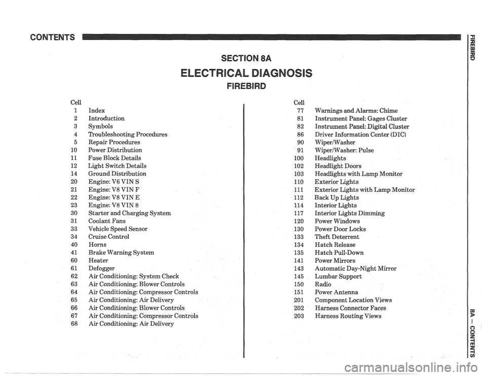
CONTENTS
ELECTRICAL DIAGNOSIS
Cell
1
2
3
4 5
10
11
12 14
20
21
22
23
30
31
33
34
40
4
1
60
61
62
63
64
65
66
67
68
Index
Introduction
Symbols
Troubleshooting Procedures Repair Procedures
Power Distribution
Fuse Block Details
Light Switch Details
Ground Distribution
Engine:
V6 VIN S
Engine: V8 VIN
F
Engine: V8 VIN E
Engine:
V8 VIN 8
Starter and Charging System
Coolant Fans
Vehicle Speed Sensor
Cruise Control Horns
Brake Warning System
Heater
Defogger
Air Conditioning: System Check
Air Conditioning: Blower Controls
Air Conditioning: Compressor Controls
Air Conditioning: Air Delivery
Air Conditioning: Blower Controls
Air Conditioning: Compressor Controls
Air Conditioning: Air Delivery Cell
77
8
1
82
86 90
9
1
100
102
103
110
111
112
114
117
120
130
133
134
135
141
143
145
150
151
201 202
203
Warnings and Alarms: Chime
Instrument Panel: Gages Cluster
Instrument Panel:
Digital Cluster
Driver Information Center
(DIC)
WiperlWasher
WiperlWasher: Pulse
Headlights
Headlight Doors
Headlights with Lamp Monitor
Exterior Lights
Exterior Lights with Lamp Monitor
Back Up Lights
Interior Lights
Interior Lights Dimming
Power Windows
Power Door Locks
Theft Deterrent
Hatch Release
Hatch Pull-Down
Power Mirrors
Automatic Day-Night Mirror
Lumbar Support
Radio Power Antenna
Component Location Views
Harness Connector Faces
Harness Routing Views
Page 1167 of 1825
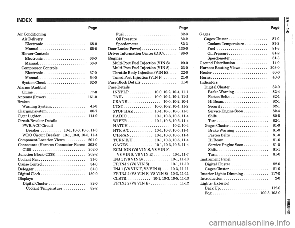
Page
Air Conditioning
Air Delivery
Electronic
.................... 68-0
Manual
....................... 65-0
Blower Controls
Electronic
.................... 66-0
Manual
....................... 63-0
Compressor Controls Electronic
.................... 67-0
Manual
....................... 64-0
................... System Check 62-0
Alarms (Audible)
Chime
......................... 77-0
Antenna(Power) ................... 151-0
Brakes
................. Warning System 41-0
................... Charging system 30-7
...................... Cigar Lighter 114-0
Circuit Breaker Details
PWR ACC Circuit
.......... Breaker 10.1.10.3.10.5.1 1.3
WDO Circuit Breaker
10.1. 10.3. 10.5. 11-4
.......... Component Location Views 201-0
Connectors (Harness Connector Faces) 202-0
el00 .......................... 202-0
............... Junction Block ((2238) 202-2
Coolant Fan
....................... 31-0
Cruise Control
..................... 34-0
Defogger
......................... 61-0
Digital Clock
...................... 150-0
Displays Digital Cluster
.................. 82-0
Coolant Temperature
........... 82-2
Page
......................... Fuel 82-3
................... Oil Pressure 82-2
.................. Speedometer 82-3
................. Door Locks (Power) 130-0
...... Driver Information Center (DIC) 86-0
Engines
... Multi-Port Fuel Injection (VIN S) 20-0
.... Multi-Port Fuel Injection (VIN 8) 23-0
.... Throttle
Body Injection (VIN E) 22-0
...... Tuned
Port Injection (VIN F) 21-0
................. Fuse Block Details 11-0
Fuse Details
........... INST LP 10.0.10.2.10.4.1 1.1
.............. TAIL 10.0.10.2.10.4.1 1.2
................ CRANK 10.0.10.2.1 0.4
.............. CTSY 10~0.10.2.10.4.1 1.2
......... STOP HAZ 10.1.10.3.10.5.1 1.3
............ RADIO 10.1.10.3.10.5.1 1.4
............ WIPER 10.1.10.3.10.5.1 1.4
.................... HATCH 10.2.1 0.4
........... HTR AlC 10.1.10.3.10.5.1 1.4
........... CIH.FAN 10.1.10.3.10.5.1 1.4
......... TURN BIU 10.1.10.3.10.5.1 1.4
............ GAGES 10.1.10.3.10.5.1 1.4
ECM-IGN
(V6 VIN S. V8 VIN F.
........ V8 VIN 8. V8 VIN E) 10.1.1 1.7
............ INJ 1 (V6 VIN S) 10.1.1 1.10
......... FPIINJ 2 (V6 VIN S) 10.1.1 1.10
... INJ 1 (V8 VIN F. V8 VIN 8) 10.3.1 1.11
FPIINJ 2 (V8 VIN F. V8 VIN 8) 10.3.1 1.11
............ CLSTR 10.1.10.3.10.5.1 1.13
............. FPIINJ 2 (V8 VIN E) 11-12
Page
Gages
................... Gages Cluster 81-0
........... Coolant Temperature 81-2
......................... Fuel 81-3
................... Oil Pressure 81-2
.................. Speedometer 81-3
................ Ground Distribution 14-0
Harness Routing Views
............. 203-0
........................... Heater 60-0
............................ Horns 40-0
Indicators
.................. Digital Cluster 82-0
................ Brake Warning 82-4
.................. Fasten Belts 82-1
...................... Hi Beam 82-1
...................... Security 82-1
............ Service Engine Soon 82-4
......................... Shift 82-5
......................... Turn 82-1
................... Gages Cluster 81-0
................ Brake Warning 81-0
.................. Fasten Belts 81-0
...................... Hi Beam 81-0
............ Service Engine Soon 81-0
......................... Shift 81-1
......................... Turn 81-0
Instrument Panel
Digital Cluster
.................. 82-0
Gages Cluster
................... 81-0
............ Interior Lights Dimming 117-0
...................... Introduction 2-0
Lights (Exterior)
........................ Back Up 112-0
...................... Fog 100.3,10 3.0
Page 1212 of 1825
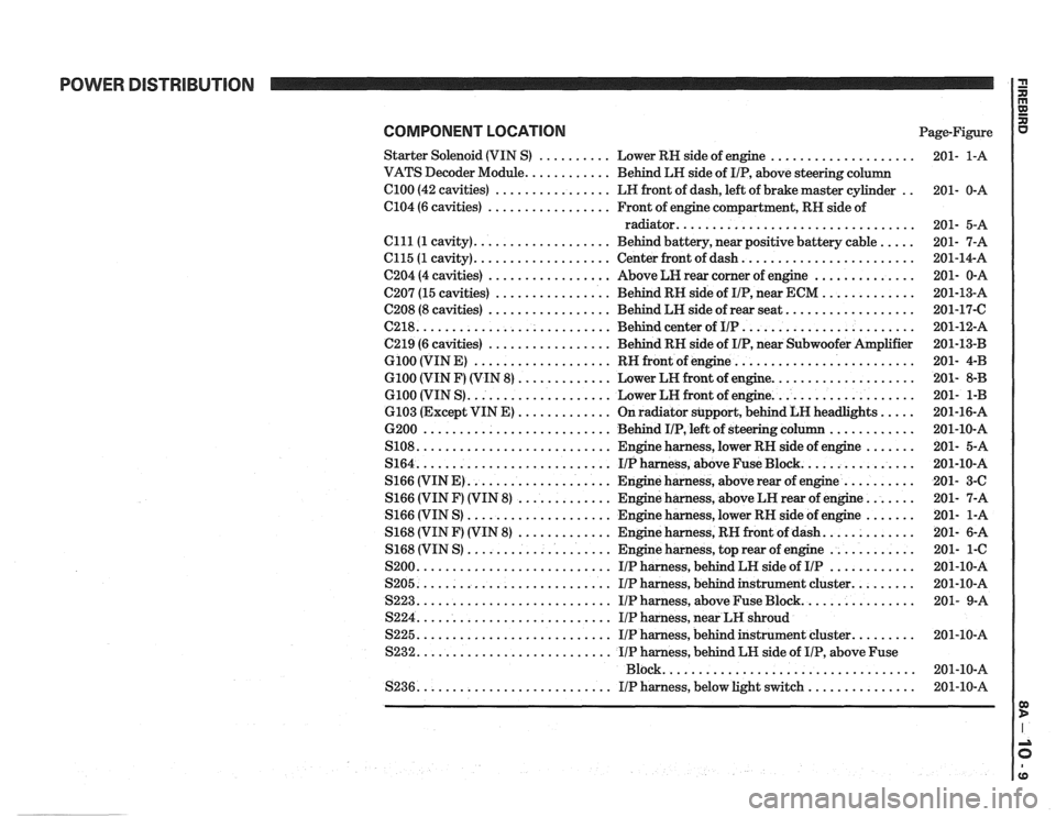
POWER DISTRIBUTION
COMPONENT LOCATION Page-Figure
Starter Solenoid (VIN
S) .......... Lower RH side of engine ....................
VATS Decoder Module ............ Behind LH side of IIP. above steering column
el00 (42 cavities) ................ LH front of dash. left of brake master cylinder ..
C104 (6 cavities) ................. Front of engine compartment. RH side of
radiator
.................................
Clll(1 cavity) ................... Behind battery. near positive battery cable .....
C115 (1 cavity) ................... Center front of dash ........................
C204 (4 cavities) ................. Above LH rear corner of engine ..............
C207 (15 cavities) ................ Behind RH side of IIP. near ECM .............
C208 (8 cavities) ................. Behind LH side of rear seat ..................
(2218 ........................... Behind center of IIP ........................
C219 (6 cavities) ................. Behind RH side of IIP. near Subwoofer Amplifier
G100 (VIN E) ................... RH front of engine .........................
G100 (VIN F) (VIN 8) ............. Lower LH front of engine ....................
G100 (VIN S) .................... Lower LH front of engine ....................
6103 (Except VIN E) ............. On radiator support. behind LH headlights .....
6200 .......................... Behind IIP. left of steering column ............
S108 ........................... Engine harness. lower RH side of engine .......
S164 ........................... IIPharness. aboveFuseBlock ................
S166 (VIN E) .................... Engine harness. above rear of engine ..........
S166 (VIN F) (VIN 8) ............. Engine harness. above LH rear of engine .......
S166 (VIN S) .................... Engine harness. lower RH side of engine .......
S168 (VIN F) (VIN 8) ............. Engine harness. RH front of dash .............
S168 (VIN S) .................... Engine harness. top rear of engine ............
S200 ........................... IIP harness. behind LH side of IIP ............
S205 ........................... IIP harness. behind instrument cluster .........
S223 ........................... IIP harness. above Fuse Block ................
S224 ........................... IIP harness. near LH shroud
S225
........................... IIP harness. behind instrument cluster .........
S232 ........................... IIP harness. behind LH side of IIP. above Fuse
................................... Block
S236
........................... IIP harness. below light switch ...............
Page 1250 of 1825
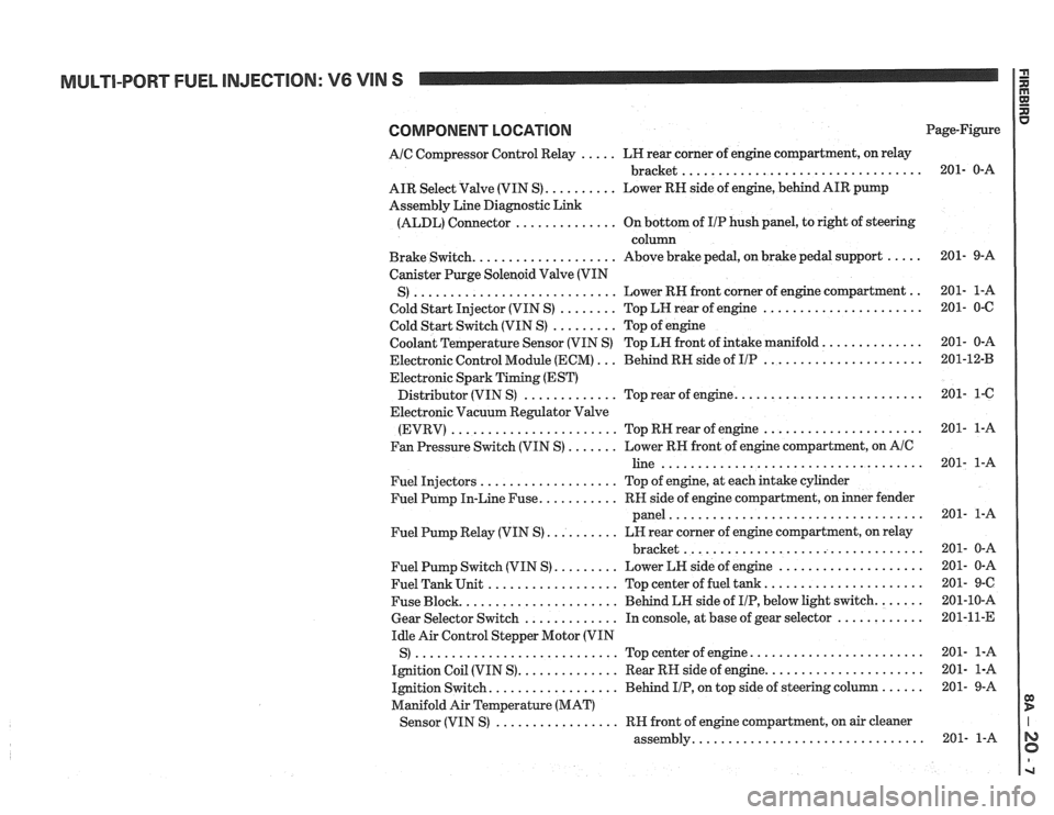
MULTI-PORT FUEL INJECTION: V6 VIN S
COMPONENT LOCATION
AIC Compressor Control Relay ..... LH rear corner of engine compartment, on relay
................................. bracket
AIR Select Valve (VIN S)
.......... Lower RN side of engine, behind AIR pump
Assembly Line Diagnostic Link
(ALDL) Connector
.............. On bottom of IIP hush panel, to right of steering
column
Brake Switch.
................... Above brake pedal, on brake pedal support .....
Canister Purge Solenoid Valve (VIN
............................ .. S) Lower RH front
corner of engine compartment
Cold Start Injector (VIN S)
........ Top LH rear of engine ......................
Cold Start Switch (VIN S) ......... Top of engine
Coolant Temperature Sensor (VIN S) Top LN front of intake manifold.
.............
Electronic Control Module (ECM) ... Behind RH side of IIP ......................
Electronic Spark Timing (EST)
......................... Distributor (VIN S) ............. Top rear of engine.
Electronic Vacuum Regulator Valve
(EVRV)
....................... TopRHrearofengine ......................
Fan Pressure Switch (VIN S) ....... Lower RH front of engine compartment, on AIC
line ....................................
Fuel Injectors ................... Top of engine, at each intake cylinder
Fuel Pump In-Line Fuse.
.......... RH side of engine compartment, on inner fender
panel
...................................
Fuel Pump Relay (VIN S) .......... LH rear corner of engine compartment, on relay
................................. bracket
Fuel Pump Switch (VIN S)
......... Lower LH side of engine ....................
Fuel Tank Unit .................. Top center of fuel tank ......................
Fuse Block. ..................... Behind LH side of IIP, below light switch. ......
Gear Selector Switch ............. In console, at base of gear selector ............
Idle Air Control Stepper Motor (VIN
S)
............................ Topcenterofengine ........................
Ignition Coil (VIN S). ............. Rear RH side of engine. .....................
Ignition Switch. ................. Behind IIP, on top side of steering column ......
Manifold Air Temperature (MAT)
................. Sensor (VIN S) RH front of engine compartment, on air cleaner
............................... assembly. Page-Figure