1988 PONTIAC FIERO brake light
[x] Cancel search: brake lightPage 1394 of 1825
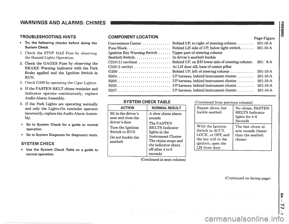
WARNINGS AND ALARMS: CHIMES
TROUBLESHOOTING H lNTS
* Try the following checks before doing the
System Check.
1. Check the STOP HAZ Fuse by observing
the Hazard Lights Operation.
2. Check the GAGES Fuse by observing the
BRAKE Warning Indicator with the Park
Brake applied and the Ignition Switch in
RUN.
3. Check 6200 by operating the Cigar Lighter.
4. If the FASTEN BELT chime reminder and
indicator operate continuously, replace
Audio Alarm Assembly.
5. If the Park Lights are operating normally
and only the Lights-On reminder operates
incorrectly, replace the Audio Alarm Assem-
bly.
Go to System Check for a guide to normal
operation.
Go to System Diagnosis for diagnostic tests.
SYSTEM CHECK
* Use the System Check Table as a guide to
normal operation.
COMPONENT LOCATlON Page-Figure
Convenience Center
.............. Behind IIP, to right of steering column. ........ 201-10-A
Fuse Block.
..................... Behind LH side of IIP, below light switch. ...... 201-10-A
Ignition Key Warning Switch
...... Upper part of steering column
Seatbelt Switch. ................. In driver's seatbelt buckle
C210
(11 cavities) ................ Behind IIP, on RH lower side of steering column. 201-
9-A
6325 (1 cavity) .................. At LH door sill, base of center pillar
6200 .......................... Behind IIP, left of steering column ............ 201-10-A
S204. .......................... IIP harness, behind instrument cluster. ........ 201-10-A
S205. .......................... IIP harness, behind instrument cluster. ........ 201-10-A
S225. .......................... I/P harness, behind instrument cluster. ........ 201-10-A
S227. .......................... IIP harness, behind instrument cluster. ........ 201-10-A
SYSTEM CHECK TABLE
ACTION
Sit in the driver's
seat and close the
driver's door
Turn the Ignition
Switch to RUN
Do not buckle the
seatbelt
NORMAL RESULT
A slow chime alarm
sounds
The FASTEN
BELTS Indicator
lights in the
Instrument Cluster
The chime stops and
the indicator shuts
off after 4 to
8
(Continued from previous column)
buckle
seatbelt
ignition, open the
LH front door
I seconds
(Continued in next column)
(Continued on facing page)
Page 1404 of 1825
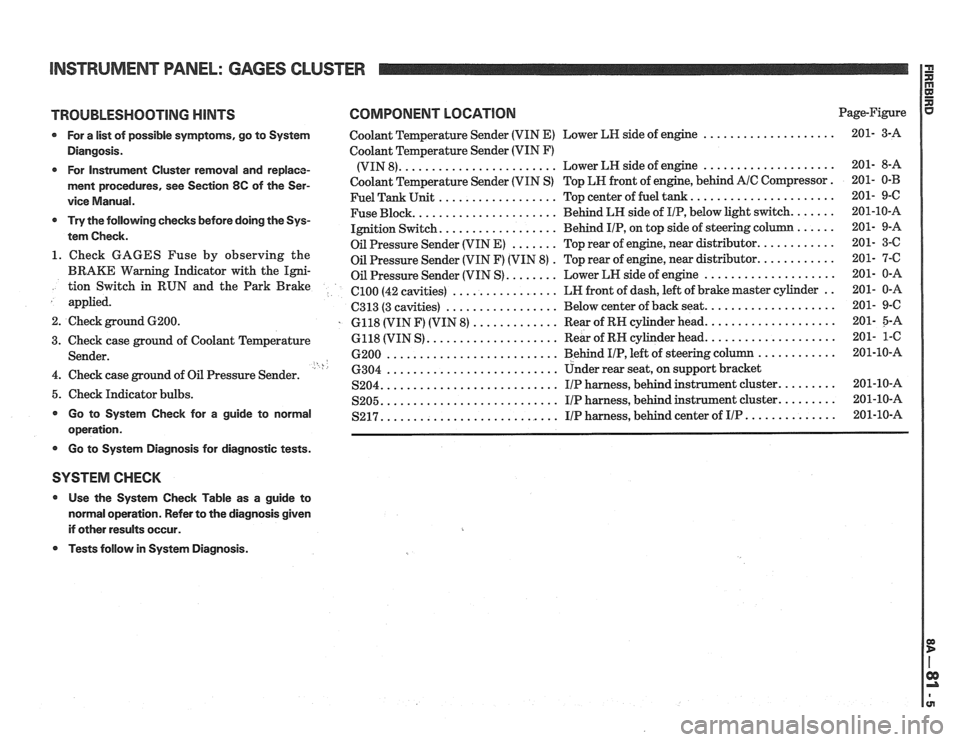
INSTRUMENT PANEL: GAGES CLUSTER
TROUBLESHOOTING HINTS COMPONENT LOCATION Page-Figure
* For a list of possible symptoms, go to System Coolant Temperature Sender (VIN E) Lower LH side of engine ....................
Diangosis. Coolant Temperature Sender (VIN F)
....................... .................... * For Instrument Cluster removal and replace- (VIN 8). Lower
LH side of engine
ment procedures, see Section 8C of the Ser- Coolant Temperature Sender (VIN S) Top LN front of engine, behind A/C Compressor.
.................. ..................... vice Manual. Fuel Tank Unit Top center of fuel tank.
..................... ...... * Try the following checks before doing the Sys- Fuse Block. Behind
LH side of IIP, below light switch.
................. tem Check. Ignition Switch. Behind IIP, on
top side of steering co
....... ........... Oil Pressure Sender (VIN E) Top rear of engine, near distributor. 1. Check GAGES Fuse by observing the . ........... Oil Pressure Sender (VIN F) (VIN 8) Top
rear of engine, near distributor.
BRAKE Warning Indicator with the Igni- Oil Pressure Sender (VIN S) ........ Lower LN side of engine .................... tion Switch in RUN and the Park Brake ................ .. el00 (42 cavities) LN
front of dash, left of brake master cylinder
applied.
................. C313 (3 cavities) Below
center of back seat. ...................
2. Check ground 6200. . 6118 (VIN F) (VIN 8) ............. Rear of RN cylinder head. ...................
.................... ................... 3. Check case ground of Coolant Temperature 6118
(VIN S) Rear
of RH cylinder head.
.......................... ............ Sender. 6200 Behind I/P, left of steering column ' h .......................... 4. Check case ground of Oil Pressure Sender. 6304 Under rear seat,
on support bracket
.......................... S204. IIP harness, behind instrument cluster. ........ 5. Check Indicator bulbs. .......................... ........ S205. I/P harness, behind instrument cluster. * Go to System Check for a guide to normal .......................... S217. I/P harness, behind center of IIP .............. operation.
* Go to Systern Diagnosis for diagnostic tests.
SYSTEM CHECK
* Use the System Check Table as a guide to
normal operation. Refer to the diagnosis given
if other results occur.
* Tests follow in System Diagnosis.
Page 1406 of 1825
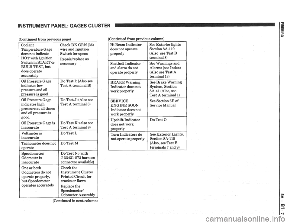
INSTRUMENT PANEL: GAGES CLUSTER
I Oil Pressure Gage
(Continued from previous page)
indicates low
pressure
and oil
pressure is good
Coolant
Temperature Gage
does not indicate
HOT with Ignition
Switch in START or
BULB TEST, but
does operate
accurately
Do Test I: (Also see
Test A
terminal B)
Check DK GRN (35)
wire and Ignition
Switch for opens
Repairlreplace as
necessary
Oil Pressure Gage
indicates high
pressure at
all times
and oil pressure is
good Do
Test
J: (Also see
Test A terminal
8)
Oil Pressure Gage is
inaccurate Do
Test K: (also see
Test A terminal
8)
Do Test L
Tachometer does not
operate
Speedometer1
Odometer is
inaccurate Do
Test M
Do Test N: (with
5-33431-873 harness
connector available)
One or both
Odometers do not
operate properly,
but Speedometer
operates accurately
I
Check the
Instrument Cluster
Printed Circuit for
cracks or flaws
Replace the
Speedometer1
Odometer Assembly
(Continued in next column) (Continued from previous
column)
Hi Beam Indicator
does not operate
properly See
Exterior lights
Section 8A-110
(Also see Test
B
terminal 8)
I operate properly
I
(Also see Test A
I
Seatbelt Indicator
and alarm do not
BRAKE Warning Indicator does not
work properly
I
See Warnings and
Alarms (see Index)
SERVICE
ENGINE SOON
Indicator does not
does not work See
Brake Warning
System, Section
8A-41 (Also, see
Test A terminal
1)
See Section 6E of
1 Service Manual
Do Test O
r
(Also, see Test B
terminals 7 and
9)
Page 1420 of 1825
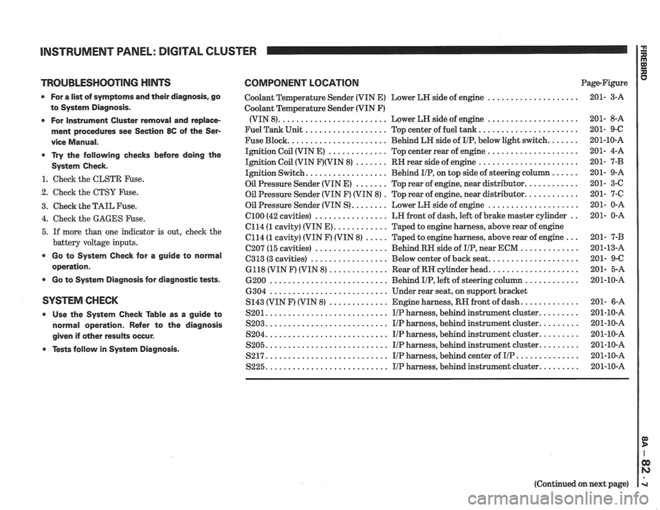
INSTRUMENT PANEL: DIGITAL CLUSTER a
TROUBLESHOOTING HINTS COMPONENT LOCATION u Page-Figure
0 For a list of symptoms and their diagnosis. go
to System Diagnosis
.
0 For Instrument Cluster removal and replace-
ment procedures see Section
86 of the Ser-
vice Manual
.
* Try the following checks before doing the
System Check
.
1 . Check the CLSTR Fuse .
2 . Check the CTSY Fuse .
3 . Check the TAIL Fuse .
Coolant Temperature Sender (VIN E) Lower LH side of engine ....................
Coolant Temperature Sender (VIN F)
(VIN 8)
........................ Lower LH side of engine ....................
Fuel Tank Unit .................. Top center of fuel tank ......................
Fuse Block ...................... Behind LH side of IIP. below light switch .......
Ignition Coil (VIN E) ............. Top center rear of engine ....................
Ignition Coil (VIN F)(VIN 8) ....... RH rear side of engine ......................
Ignition Switch .................. Behind IIP. on top side of steering column ......
Oil Pressure Sender (VIN E) ....... Top rear of engine. near distributor ............
Oil Pressure Sender (VIN F) (VIN 8) . Top rear of engine. near distributor ............
Oil Pressure Sender (VIN S) ........ Lower LH side of engine ....................
................ .. 4 . Check the GAGES Fuse . el00 (42 cavities) LH
front of dash. left of brake master cylinder 201- 0-A
C114
(1 cavity) (VIN E) ............ Taped to engine harness. above rear of engine
5 . If more than one indicator is out. check the C114 (1 cavity) (VIN F) (VIN 8) ..... Taped to engine harness. above rear of engine ... 201- 7-B
battery voltage inputs . . C207 (15 cavities) ................ Behind RH side of IIP near ECM ............. 201-13-A
................. .................... * Go to System Check for a guide to C313 (3 cavities) Below
center of back seat 201- 9-C operation . 6118 (VIN F) (VIN 8) ............. Rear of RH cylinder head .................... 201- 5-A
0 Go to System Diagnosis for diagnostic tests . 6200 .......................... Behind IIP. left of steering column ............ 201-10-A
6304
.......................... Under rear seat. on support bracket
SYSTEM CHECK S143 (VIN F) (VIN 8) ............. Engine harness. RH front of dash ............. 201- 6-A
0 Use the System Check able as a guide to S201 ........................... IIP harness. behind instrument cluster ......... 201-10-A
normal operation . Refer to the diagnosis S203 ........................... I/P harness. behind instrument cluster ......... 201-10-A
........................... ......... given if other results occur . S204 IIP harness. behind instrument cluster 201-10-A
........................... ......... Tests follow in System Diagnosis . S205 IIP harness. behind instrument cluster 201-10-A
S217 ........................... IIP harness. behind center of IIP .............. 201-10-A
S225 ........................... IIP harness. behind instrument cluster ......... 201-10-A
(Continued on next page)
Page 1433 of 1825
DRIVER INFORMATION CENTER (DDC) I $
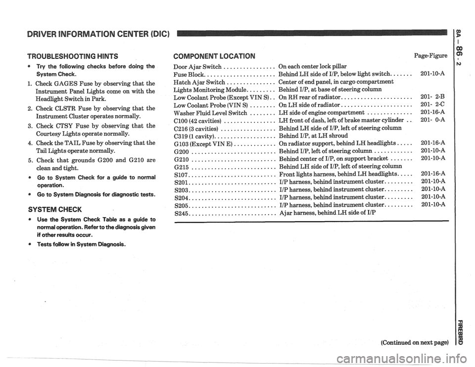
TROUBLESHOOTING HINTS
@ Try the following checks before doing the
System Check.
1. Check GAGES Fuse by observing that the
Instrument Panel Lights come on with the
Headlight Switch in Park.
2. Check CLSTR Fuse by observing that the
Instrument Cluster operates
normally.
3. Cheek CTSU Fuse by observing that the
Courtesy Lights operate normally.
4. Check the TAIL Fuse by observing that the
Tail Lights operate normally.
5. Check that grounds 6200 and 6210 are
clean and tight.
@ Go to System Check for a guide to norrnal
operation.
@ Go to System Diagnosis for diagnostic tests.
SYSTEM CHECK
@ Use the System Check Table as a guide to
normal operation. Refer to the diagnosis given
if other results occur.
Tests follow in System Diagnosis.
COMPONENT LOCATION Page-Figure
Door Ajar Switch
................ On each center lock pillar
..................... Fuse Block.
Behind LH side of IIP, below light switch. ...... 201-10-A
Hatch Ajar Switch
............... Center of end panel, in cargo compartment
Lights Monitoring Module.
........ Behind IIP, at base of steering column
..................... Low Coolant Probe (Except VIN S) .. On RR rear of radiator. 201- 2-B
..................... Low Coolant Probe (VIN S) ........ On LR side of radiator. 201- 2-C
.............. Washer Fluid Level Switch ........ LN side of engine compartment 201-16-A
................ el00 (42
cavities) LN
front of dash, left of brake master cylinder .. 201- 0-A
................. 6216 (3 cavities) Behind LN side
of IIP, left of steering column
.................. C319 (1 cavity). Behind I/P, at
LN shroud
............. 6103 (Except VIN E) On radiator support, behind LH headlights. .... 201-16-A
.......................... ............ 6200 Behind IIP, left of steering column 201-10-A
.......................... 6210 Behind center of IIP, on support bracket ....... 201-10-A
.......................... 6215 Behind
LH side of IIP, left of steering column
.......................... .... S107. Front lights harness, behind LN headlights. 201-16-A
.......................... S201. IIP harness, behind instrument cluster. ........ 201-10-A
.......................... S203. I/P harness, behind instrument cluster. ........ 201-10-A
.......................... S204. I/P harness, behind instrument cluster. ........ 201-10-A
.......................... S205. I/P harness, behind instrument cluster. ........ 201-10-A
.......................... S245. Ajar harness, behind LN side of IIP
(Continued on next page)
Page 1440 of 1825
TROUBLESHOOTING HINTS
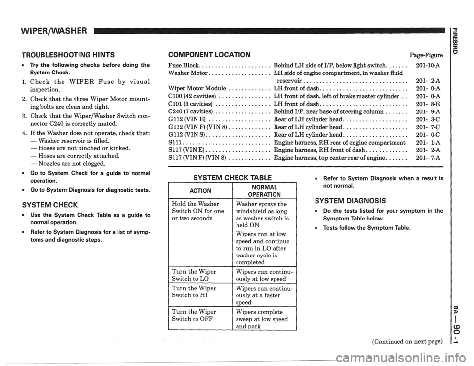
0 Try the following checks before doing the
System Check.
1. Check the WIPER Fuse by visual
inspection.
2. Check that the three Wiper Motor mount-
ing bolts are clean and tight.
3. Check that the Wiper/Washer Switch con-
nector C240 is correctly mated.
4. If the Washer does not operate, check that:
- Washer reservoir is filled.
- Hoses are not pinched or kinked.
- Hoses are correctly attached.
- Nozzles are not clogged.
r Go to System Check for a guide to, normal
operation.
0 Go to System Diagnosis for diagnostic tests.
SYSTEM C H EGK
Use the System Check Table as a guide to
normal operation.
Refer to System Diagnosis for a list of symp-
toms and diagnostic steps.
COMPONENT LOCATION Page-Figure
...... ..................... Fuse Block. Behind LH side of IIP, below light switch.
Washer Motor.
.................. LH side of engine compartment, in washer fluid
reservoir
................................
.......................... Wiper Motor Module ............. LH front of dash.
.. Cl00 (42 cavities) ................ LH front of dash, left of brake master cylinder
.......................... C101 (3 cavities) ................. LH front of dash.
....... C240 (7 cavities) ................. Behind IIP, near base of steering column
................... 6112 (VIN E) ................... Rear of LH cylinder head.
................... 6112 (VIN F) (VIN 8) ............. Rear of LH cylinder head.
................... 6112 (VIN S) .................... Rear of LW cylinder head.
Slll ........................... Engine harness, RH rear of engine compartment
............ S117 (VIN E) .................... Engine harness, RH front of dash.
...... S117 (VIN F) (VIN 8) ............. Engine harness, top center rear of engine.
SYSTEM CHECK TABLE Refer to System Diagnosis when a result is
not normal.
SYSTEM DIAGNOSIS
0 Do the tests listed for your symptom in the
Symptom Table below.
0 Tests follow the Symptom Table.
or two seconds
Wipers run at low
(Continued on next page)
. __- ______ --___ -..- .
Page 1444 of 1825
WIPERIWASHER: PULSE, CD4 I G n
TROUBLESHOOTING HINTS
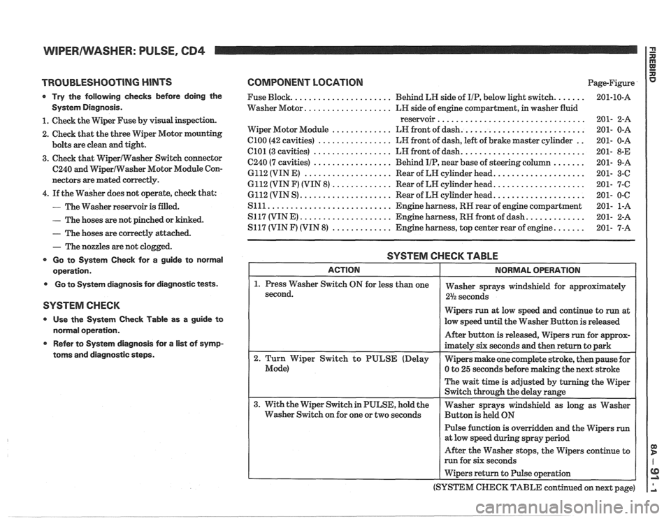
Try the following checks before doing the
System Diagnosis.
1. Check the Wiper Fuse by visual inspection.
2. Check that the three
VViper Motor mounting
bolts are clean and tight.
3. Check that Wipermasher Switch connector
C240 and WiperIWasher Motor Module Con-
nectors are mated correctly.
4. If the Washer does not operate, check that:
- The Washer reservoir is filled.
- The hoses are not pinched or kinked.
- The hoses are correctly attached.
- The nozzles are not clogged.
Go to System Check for a guide to normal
operation.
Go to System diagnosis for diagnostic tests.
SYSTEM CHECK
Use the System Check Table as a guide to
normal operation.
e Refer to System diagnosis for a list of symp-
toms and diagnostic steps.
COMPONENT LOCATION Page-Figure
...... ..................... Fuse Block. Behind LR side of IIP, below light switch.
.................. Washer Motor. LH side of engine compartment, in washer fluid
reservoir
................................
.......................... ............. Wiper Motor Module LN front of dash.
.. C100 (42 cavities) ................ LR front of dash, left of brake master cylinder
.......................... C101(3 cavities) ................. LH front of dash.
....... C240 (7 cavities) ................. Behind IIP, near base of steering column
................... 6112 (VIN E) ................... Rear of LN cylinder head.
................... 6112 (VIN F) (VIN 8) ............. Rear of LN cylinder head.
................... 6112 (VIN S) .................... Rear of LH cylinder head.
S111 ........................... Engine harness, RN rear of engine compartment
............ S117 (VINE) .................... Engine harness, RN front of dash.
...... S117 (VIN F) (VIN 8) ............. Engine harness, top center rear of engine.
SYSTEM CHECK TABLE
Wipers run at low speed and continue to run at
low speed until the Washer Button is released
Pulse function is overridden and the Wipers
run
After the Washer stops, the Wipers continue to
run for six seconds
I Wipers return to Pulse operation
(SYSTEM
CHECK TABLE continued on next page)
Page 1450 of 1825
TROUBLESHOOTING HINTS COMPONENT LOCATION Page-Figure
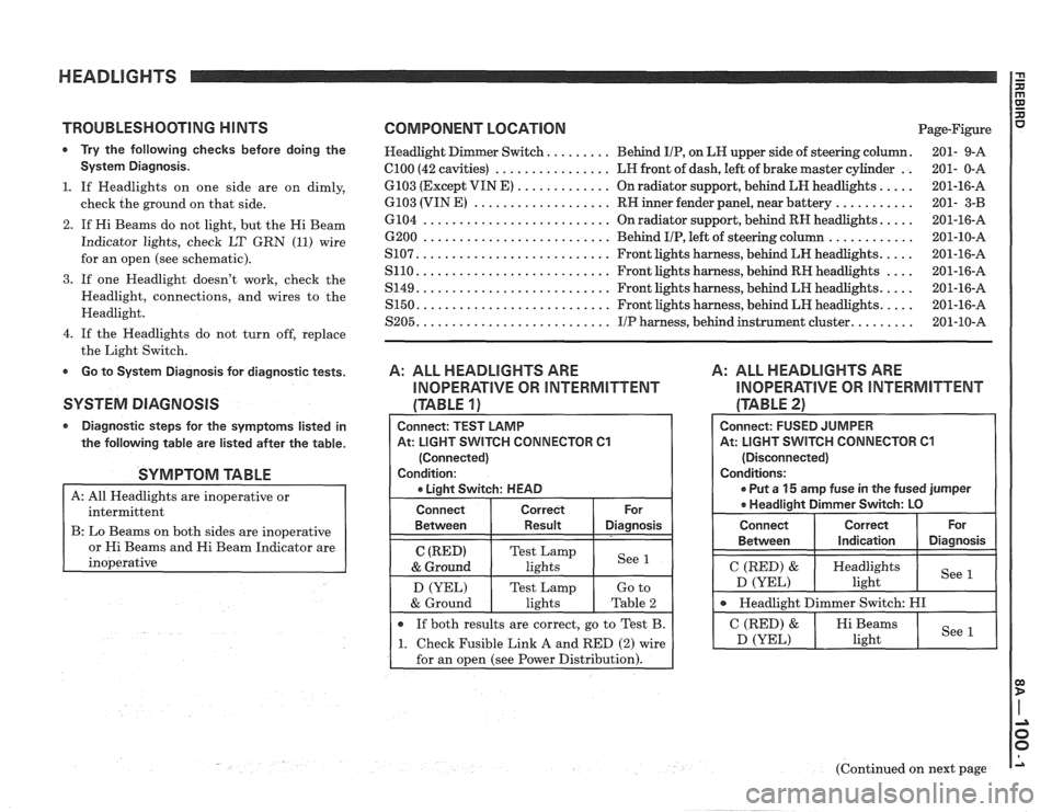
* Try the following checks before doing the Headlight Dimmer Switch. ........ Behind IIP, on LH upper side of steering column. 201- 9-A
System Diagnosis. el00 (42 cavities) ................ LH front of dash, left of brake master cylinder .. 201- 0-A
.... ............. 1. If Headlights on one side are on dimly, 6103 (Except VIN E)
On radiator support, behind LH headlights. 201-16-A
........... ................... check the ground on that side. 6103 (VIN E) RN inner fender panel, near battery 201- 3-B
2. If Hi Beams do not light, but the Hi Beam
Indicator lights, check LT
GRN (11) wire
for an open (see schematic).
3. If one Headlight doesn't work, check the
Headlight, connections, and wires to the
Headlight.
4. If the Headlights do not turn off, replace
the Light Switch.
Go to System Diagnosis for diagnostic tests.
SYSTEM DIAGNOSIS
Diagnostic steps for the symptoms listed in
the following table are listed after the table.
SYMPTOM TABLE
A: All Headlights are inoperative or
intermittent
B: Lo Beams on both sides are inoperative
s and Hi Beam Indicator are
.... .......................... 6104 On radiator support, behind RH headlights. 201-16-A
............ 6200 .......................... Behind IIP, left of steering column 201-10-A
.... .......................... S107. Front lights harness, behind LH headlights. 201-16-A
.... .......................... S110. Front lights harness, behind RH headlights 201-16-A
.... .......................... S149. Front lights harness, behind LH headlights. 201-16-A
.... S150. .......................... Front lights harness, behind LH headlights. 201-16-A
........ S205. .......................... IIP harness, behind instrument cluster. 201-10-A
A: ALL HEADLIGHTS ARE
INOPERATIVE OR INTERMITTENT
(TABLE 1)
A: ALL HEADLIGHTS ARE
INOPERATIVE OR INTERMITTENT
(TABLE 21
Connect: TEST LAMP
At: LIGHT
SVVITCH CONNECTOR C1
(Connected)
Condition:
r Liaht Switch: HEAD
Connect Correct
Between Result Diagnosis
C (RED) Test Lamp
& Ground lights See 1
D
(YEL) Test Lamp
If both results are correct, go to Test B.
1 1. Check Fusible Link A and RED (2) wire
for an open (see Power Distribution).
Connect: FUSED JUMPER
At: LIGHT
SWITCH CONNECTOR C1
(Disconnected)
Conditions:
r Put a 15 amp fuse in the fused jumper
* Headliaiht Dimmer Switch: LO
I Connect 1 Correct ( or 1
Between I Indication 1 Diagnosis I I
I C (RED) & ( Heydlights I See D (YEL) ight
I Headlight Dimmer Switch: HI I
(Continued on next page