1988 PONTIAC FIERO diagram
[x] Cancel search: diagramPage 1652 of 1825

RADIO SYSTEMS AND ANTENNAS 9A-3
antenna. Check radio reception in an area away from
reception. If reception is OK, problem exists with
electrical interferences. These include tall buildings,
antenna and/or its lead-in cable. If reception is still
metal structures, power lines, fluorescent lighting, and
poor, refer to Section
8A.
power tools. Tune to high and low ends of the dial on
both AM and FM checking weak and strong station
reception. If reception is OK, problem exists with
antenna and/or its lead-in cable. If reception is still
poor, refer to Section
8A.
Checking Lead-In Cables
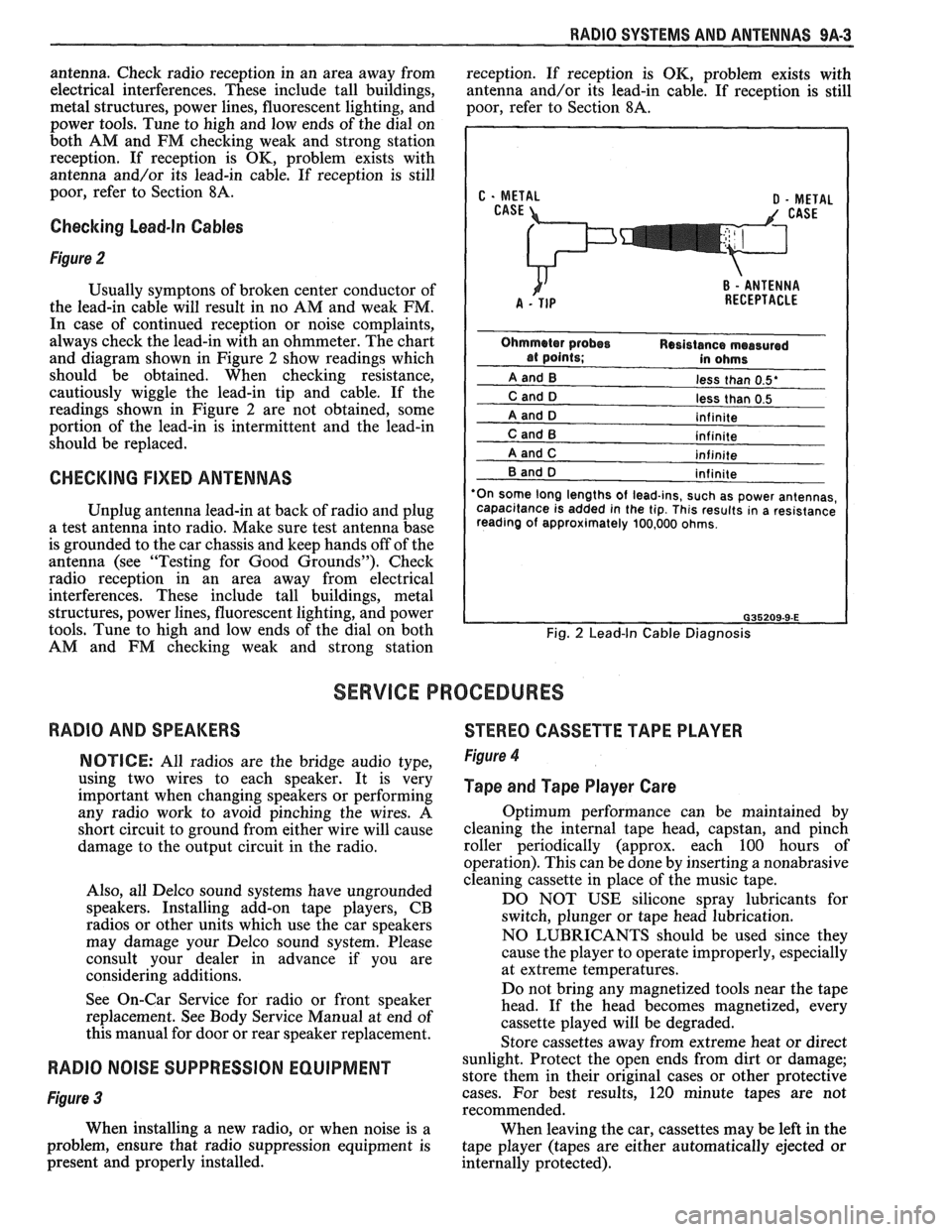
Figure 2
Usually symptons of broken center conductor of
the lead-in cable will result in no AM and weak FM.
In case of continued reception or noise complaints,
always check the lead-in with an ohmmeter. The chart
and diagram shown in Figure
2 show readings which
should be obtained. When checking resistance,
cautiously wiggle the lead-in tip and cable. If the
readings shown in Figure
2 are not obtained, some
portion of the lead-in is intermittent and the lead-in
should be replaced.
CHECKING FIXED ANTENNAS
Unplug antenna lead-in at back of radio and plug
a test antenna into radio. Make sure test antenna base
is grounded to the car chassis and keep hands off of the
antenna (see "Testing for Good Grounds"). Check
radio reception in an area away from electrical
interferences. These include tall buildings, metal
structures, power lines, fluorescent lighting, and power
tools. Tune to high and low ends of the dial on both
AM and FM checking weak and strong station
less than 0.5'
less than 0.5
'On some long lengths
of lead-ins, such as power antennas,
capacitance is added in the tip. This results in a resistance
reading of approximately 100,000 ohms.
Fig. 2 Lead-In Cable Diagnosis
SERVICE PROCEDURES
RADIO AND SPEAKERS
STEREO CASSETTE TAPE PLAYER
NOTICE: All radios are the bridge audio type,
using two wires to each speaker. It is very
important when changing speakers or performing
any radio work to avoid pinching the wires. A
short circuit to ground from either wire will cause
damage to the output circuit in the radio.
Also, all Delco sound systems have ungrounded
speakers. Installing add-on tape players, CB
radios or other units which use the car speakers
may damage your Delco sound system. Please
consult your dealer in advance if you are
considering additions.
See On-Car Service for radio or front speaker
replacement. See Body Service Manual at end of
this manual for door or rear speaker replacement. Figure 4
Tape and Tape Player Care
Optimum performance can be maintained by
cleaning the internal tape head, capstan, and pinch
roller periodically (approx. each 100 hours of
operation). This can be done by inserting a nonabrasive
cleaning cassette in place of the music tape.
DO NOT USE silicone spray lubricants for
switch, plunger or tape head lubrication.
NO LUBRICANTS should be used since they
cause the player to operate improperly, especially
at extreme temperatures.
Do not bring any magnetized tools near the tape
head. If the head becomes magnetized, every
cassette played will be degraded.
Store cassettes away from extreme heat or direct
RADIO NOISE SUPPRESSION EQUIPMENT sunlight. Protect the open ends from dirt or damage;
store them in their original cases or other protective
Figure 3 cases. For best results, 120 minute tapes are not
recommended.
When installing a new radio, or when noise is a
When leaving the car, cassettes may be left in the
problem, ensure that radio suppression equipment is
tape player (tapes are either automatically ejected or
present and properly installed.
internally protected).
Page 1682 of 1825

GENERAL INFORMATION - F STYLE 1 H-1
SECTION IH
GENERAL NFORMAT
NOTICE: The anti-theft label found on some major sheet metal, engines, and transmissions must be masked
prior to painting, rustproofing, undercoating, etc. The mask
must be removed following the above operations.
Failure to keep the label clean and readable may result in liability for violation of Federal Vehicle Theft Prevention
Standard, and subject the vehicle owner to possible suspicion that the part was stolen.
Lock Cylinder Coding
..................................... I H-1 Chip Resistant Plastisol Material .................... 1 H-8
...................................................... Lubrication 1 H-2 Flexible Exterior Plastic Parts ......................... 1H-9
Adhesive Body Side Moldings ......................... 1H-3 Metal Replacement Parts Finishing ................ lH-13
Waterleak Diagnosis and Repair ..................... 1H-3 Interior Plastic Trim Parts Finishing .............. 1H-13
.................................................... Anticorrosion Treatment ................................ IH-4 Special Tools I H- 14
LOCK CYL!NDER CODING o Check key operation in the lock cylinder.
KEY IDENTIFICATION AND USAGE
REPLACEMENT LOCK CYLINDERS
The lock cylinder keyway is designed so that
other model keys will not enter a current model lock
cylinder. Two noninterchangeable keys are used.
CB Square headed key is used in the ignition lock
cylinder.
o Oval headed key is used in all other lock
cylinders.
Key identification is obtained from the four
character key code stamped on the knockout portion
of the key head and an identification letter stamped on
the key shank. After the code number has been
recorded by the owner, the plugs should be knocked
out of the key head. From these numbers, the lock
combination can be determined by use of a code list
(available to owners of key cutting equipment from
equipment suppliers). If key code numbers are not
available from records or from the knockout plug, the
lock combination (tumbler numbers and position) can
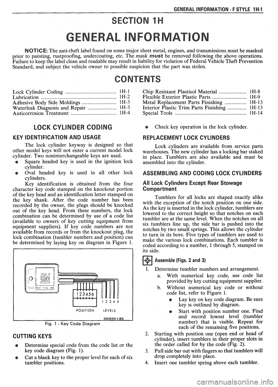
be determined by laying key on diagram in Figure
1.
I POSITION LEVELS I
Fig. 1 - Key Code Diagram
CUTTING KEYS
Lock cylinders are available from service parts
warehouses. The new cylinder has a locking bar staked
in place. Tumblers are also available and must be
assembled into the cylinder.
ASSEMBLING AND CODING LOCK CYLINDERS
All Lock Cylinders Except Rear Stowage
Compartment
Tumblers for all locks are shaped exactly alike
with the exception of the notch position on one side.
As the key is inserted in the lock cylinder, tumblers are
lowered to the correct height so that notches on each
tumbler are at the same level. When the notches on all
six tumblers line up, the side bar is pushed into the
notches by two small springs. This allows the cylinder
to turn in its bore. Five types of tumblers are used to
make the various lock combinations. Each tumbler is
coded according to a number,
1 through 5, stamped on
its side.
Assemble (Figs. 2 and 3)
1. Determine tumbler numbers and arrangement.
a. With numerical
key code, use code list
provided by key cutting equipment supplier.
b. Without numerical
key code or without
code list, refer to Figure
1.
o Lay key on key code diagram. Be sure
key is outlined by diagram.
Determine special code from the code list or the
key code diagram (Fig.
1). 3.
o Cut a blank key to the proper level for each of six
tumbler positions.
4.
Start with position number one. Find
and record lowest level (tumbler
number) that is visible. Repeat for
each of the remaining five positions.
Starting with position one [open end or head of
cylinder), insert tumblers in their proper slots in
the order called for by the code (Fig.
2).
Pull side bar out with fingers so that tumblers will
drop completely into place.
Insert one tumbler spring above each tumbler.