1988 PONTIAC FIERO ECU
[x] Cancel search: ECUPage 1167 of 1825
Page
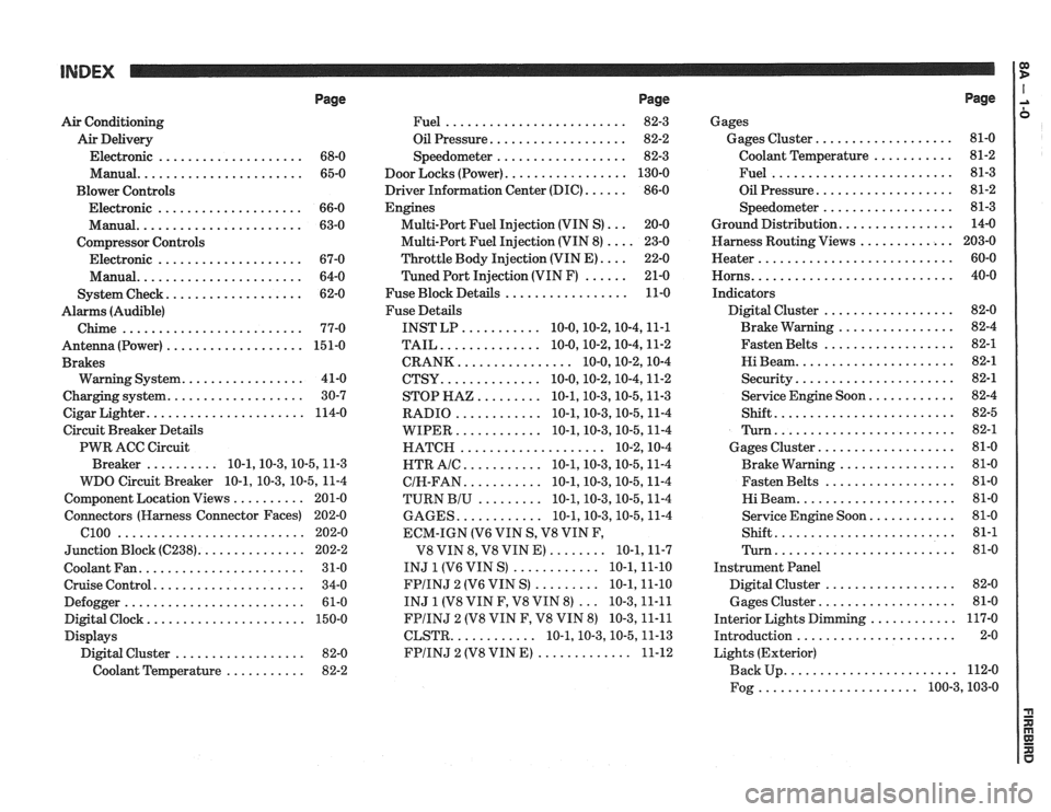
Air Conditioning
Air Delivery
Electronic
.................... 68-0
Manual
....................... 65-0
Blower Controls
Electronic
.................... 66-0
Manual
....................... 63-0
Compressor Controls Electronic
.................... 67-0
Manual
....................... 64-0
................... System Check 62-0
Alarms (Audible)
Chime
......................... 77-0
Antenna(Power) ................... 151-0
Brakes
................. Warning System 41-0
................... Charging system 30-7
...................... Cigar Lighter 114-0
Circuit Breaker Details
PWR ACC Circuit
.......... Breaker 10.1.10.3.10.5.1 1.3
WDO Circuit Breaker
10.1. 10.3. 10.5. 11-4
.......... Component Location Views 201-0
Connectors (Harness Connector Faces) 202-0
el00 .......................... 202-0
............... Junction Block ((2238) 202-2
Coolant Fan
....................... 31-0
Cruise Control
..................... 34-0
Defogger
......................... 61-0
Digital Clock
...................... 150-0
Displays Digital Cluster
.................. 82-0
Coolant Temperature
........... 82-2
Page
......................... Fuel 82-3
................... Oil Pressure 82-2
.................. Speedometer 82-3
................. Door Locks (Power) 130-0
...... Driver Information Center (DIC) 86-0
Engines
... Multi-Port Fuel Injection (VIN S) 20-0
.... Multi-Port Fuel Injection (VIN 8) 23-0
.... Throttle
Body Injection (VIN E) 22-0
...... Tuned
Port Injection (VIN F) 21-0
................. Fuse Block Details 11-0
Fuse Details
........... INST LP 10.0.10.2.10.4.1 1.1
.............. TAIL 10.0.10.2.10.4.1 1.2
................ CRANK 10.0.10.2.1 0.4
.............. CTSY 10~0.10.2.10.4.1 1.2
......... STOP HAZ 10.1.10.3.10.5.1 1.3
............ RADIO 10.1.10.3.10.5.1 1.4
............ WIPER 10.1.10.3.10.5.1 1.4
.................... HATCH 10.2.1 0.4
........... HTR AlC 10.1.10.3.10.5.1 1.4
........... CIH.FAN 10.1.10.3.10.5.1 1.4
......... TURN BIU 10.1.10.3.10.5.1 1.4
............ GAGES 10.1.10.3.10.5.1 1.4
ECM-IGN
(V6 VIN S. V8 VIN F.
........ V8 VIN 8. V8 VIN E) 10.1.1 1.7
............ INJ 1 (V6 VIN S) 10.1.1 1.10
......... FPIINJ 2 (V6 VIN S) 10.1.1 1.10
... INJ 1 (V8 VIN F. V8 VIN 8) 10.3.1 1.11
FPIINJ 2 (V8 VIN F. V8 VIN 8) 10.3.1 1.11
............ CLSTR 10.1.10.3.10.5.1 1.13
............. FPIINJ 2 (V8 VIN E) 11-12
Page
Gages
................... Gages Cluster 81-0
........... Coolant Temperature 81-2
......................... Fuel 81-3
................... Oil Pressure 81-2
.................. Speedometer 81-3
................ Ground Distribution 14-0
Harness Routing Views
............. 203-0
........................... Heater 60-0
............................ Horns 40-0
Indicators
.................. Digital Cluster 82-0
................ Brake Warning 82-4
.................. Fasten Belts 82-1
...................... Hi Beam 82-1
...................... Security 82-1
............ Service Engine Soon 82-4
......................... Shift 82-5
......................... Turn 82-1
................... Gages Cluster 81-0
................ Brake Warning 81-0
.................. Fasten Belts 81-0
...................... Hi Beam 81-0
............ Service Engine Soon 81-0
......................... Shift 81-1
......................... Turn 81-0
Instrument Panel
Digital Cluster
.................. 82-0
Gages Cluster
................... 81-0
............ Interior Lights Dimming 117-0
...................... Introduction 2-0
Lights (Exterior)
........................ Back Up 112-0
...................... Fog 100.3,10 3.0
Page 1188 of 1825
REPAIR PROCEDURES
Fusible Links
In addition to circuit breakers and fuses,
some circuits use fusible links to protect the
wiring. Like fuses, fusible links are "one time
"
protection devices that will melt and create an
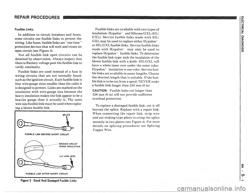
open circuit (see Figure
3).
Not all fusible link open circuits can be
detected by observation. Always inspect that
there is Battery voltage past the fusible link to
verify continuity.
Fusible links are used instead of a fuse in
wiring circuits that are not normally fused,
such as the ignition circuit. Each fusible link is
four wire-gauge sizes smaller than the cable it
is designed to protect. Links are marked on the
insulation with wire-gauge size because the
heavy insulation makes the link appear to be a
heavier gauge than it actually is. The same
wire size fusible link must be used when replac-
ing a blown fusible link.
FUSIBLE LINK BEFORE SHORT CIRCUIT
, BROKEN CIRCUIT INSIDE INSULATION
Fusible links are available with two types of
insulation: Hypalon
bnd SiliconelGXL (SILI
GXL). Service fusible links made with SILI
GXL may be used to replace either Hypalon "
or SILIGXL fusible links. Service fusible links
made with
Hypalonday only be used to
replace Hypalon
"fusible links. To determine
the fusible link type: nick the insulation of the
blown fusible link with a knife.
SILIGXL will
have a white inner core under the outer color.
Hypalon
"nsulation is one color. Service fusi-
ble links are available in many lengths. Choose
the shortest length that is suitable.
If the fusi-
ble link is to be cut from a spool, NEVER make
a fusible link longer than 228 mm
(9 in).
CAUTION: Fusible links cut longer than
228 mm
(9 in) will not provide sufficient
overload protection.
To replace a damaged fusible link, cut it off
beyond the splice. Replace with a repair link.
When connecting the repair link. strip wire
and use staking-type pliers to crimp the splice
securely in two places (see Figure
4). For more
details on splicing procedures see Splicing
Copper Wire.
R SHORT CIRCUIT
Figure 3 - Good And Damaged Fusible Links
-- - - - - -- - - - - -- - - -
Page 1190 of 1825
REPAIR PROCEDURES
Step Three: Strip the Insulation
When replacing a wire. use a wire of the same
size as the original wire or larger. The schemat-
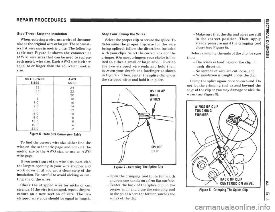
ics list wire size in metric units. The following
table (see Figure
6) shows the commercial
(AWG) wire sizes that can be used to replace
each
metric wire size. Each AWG size is either
equal to or larger than the equivalent metric
size.
METRIC WIRE
SIZES
.22
.35
.5
.8
13.0
32.0
AWG
SIZES
Figure 6 - Wire Size Conversion Table
To find the correct wire size either find the
wire on the schematic page and convert the
metric size to the AR'G size. or use an
An'(;
wire gage.
If you aren't sure of the wire size. start with
the largest opening in your wire stripper and
work down until you get a clean strip of the
insulation. Be careful to avoid nicking or cut-
ting any of the wires.
Check the stripped wire for nicks or cut
strands. If the wire is damaged. repeat the pro-
cedure on a new section of wire. The two
stripped wire ends should be equal in length.
Step Four: Crirnp the Wires
Select the proper clip to secure the splice. '1'0
determine the proper clip size for the wire
heing spliced. follow the directions included
with your clips. Select the correct anvil on the
crimper. (On most crimpers your choice is
lim-
ited to either a small or large anvil.) Overlap
the two stripped wire ends and hold them
between your
thumb and forefinger as shown
in Figure
7. Then, center the splice clip under
the stripped wires and hold it in place.
-Open the crimping tool to its full width
and rest one handle on a firm flat surface.
--Center the back of the splice clip on the
proper
anvil and close the crinlping tool
to the point where the former touches the
wings of the clip. -Make
sure that the clip and wires are still
in the correct position. Then, apply
steady pressure until the crimping tool
closes (see Figure
8).
Before crimping the ends of the clip, be sure
that:
--The wires extend beyond the clip in
each direction.
-No strands of wire are cut loose, and
-No insulation is caught under the clip.
Crirnp the splice again. once on each end. Do
not let the crimping tool extend beyond the
edge of the clip or you may damage or nick the
wires (see Figure
9).
/ CENTERED ON ANVIL
Figure 8 - Crimping The Splice Clip
Page 1198 of 1825
REPAIR PROCEDURES
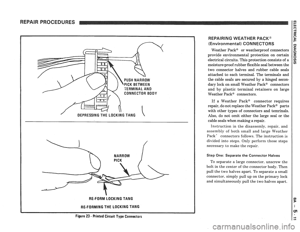
PUSH NARROW
PICK BETVVEEN
TERMINAL AND
CONNECTOR BODY
RE-FORM LOCKING TANG
RE-FORMING THE LOCKING TANG
REPAIRING WEATHER PACK@
(Environmental) CONNECTORS
Weather Pack@ or weatherproof connectors
provide environmental protection on certain
electrical circuits. This protection consists of a
moisture-proof rubber flexible seal between the
two connector halves and rubber cable seals
attached to each terminal. The terminals and
the cable
seals are secured by a hinged secon-
dary lock on small Weather Pack@ connectors
and by plastic terminal retainers on large
Weather Pack@ connectors.
If a Weather PackB connector requires
repair, do not replace the Weather Pack@ parts
with other types of connectors and temrinals.
Also, do not omit either the large seal or the
cable seals when making a repair.
Instruction in the disassemly, repair, and
assembly of both small and large Weather
PackR connectors follows. The instruction is
divided into steps. Only perform those steps
necessary to make the repair.
Step One: Separate the Connector Halves
To separate a large connector, unscrew the
bolt in the center of the connector body. Then
pull the two halves apart. To separate a small
connector, simply pull up on the primary lock
and simultaneously pull the two halves apart.
Figure 23 - Printed Circuit Type Connectass
Page 1512 of 1825
THEFT DETERRENT SYSTEM: PASSKEY I a
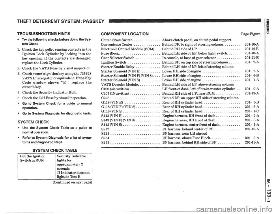
TROUBLESHOOTING HINTS COMPONENT LOCATION
Try the following checks before doing the Sys-
tem Check.
1. Check the key pellet sensing contacts in the
Ignition Lock Cylinder by looking into the
key opening. If the contacts are damaged,
replace the Lock Cylinder.
2. Check the VATS Fuse by visual inspection.
3. Check owner's ignition key using the 535628
VATS Interrogator or equivalent.
If the Key
Code window shows "E", replace the
owner's key.
4. Check the Security Indicator Bulb.
5. Check the
CIH Fuse by visual inspection.
Go to System Check for a guide to normal
operation.
Go to System Diagnosis for diagnostic tests.
SYSTEM CHECK
Use the System Check Table as a guide to
normal operation.
r Refer to System Diagnosis for a list of symp-
toms and diagnostic steps.
Clutch Start Switch .............. Above clutch pedal, on clutch pedal support
Convenience Center
.............. Behind IIP, to right of steering column. ........
Electronic Control Module (ECM) ... Behind RN side of IIP ......................
Fuse Block. ..................... Behind LH side of IIP, below light switch. ......
Gear Selector Switch ............. In console, at base of gear selector ............
Ignition Switch. ................. Behind IIP, on top side of steering column ......
Starter Enable Relay ............. Behind LH side of IIP, left of steering column
Starter Solenoid (VIN E)
.......... Lower RH side of engine ....................
Starter Solenoid (VIN F) (VIN 8). ... Lower RH side of engine ....................
Starter Solenoid (VIN S) .......... Lower RN side of engine ....................
VATS Decoder Module. ........... Behind LH side of IIP, above steering column
Cl00 (42 cavities) ................ LH front of dash, left of brake master cylinder ..
C207 (15 cavities) ................ Behind RN side of IIP, near ECM .............
6228. .......................... Behind IIP, on upper RH side of steering column
6118 (VIN
E) ................... Rear of RN cylinder head. ...................
6118 (VIN F) (VIN 8) ............. Rear of RH cylinder head. ...................
6118 (VIN S) .................... Rear of RN cylinder head. ...................
S143 (VIN E) .................... Engine harness, RR front of dash. ............
S143 (VIN F) (VIN 8) ............. Engine harness, RN front of dash. ............
S143 (VIN S) .................... Engine harness, center front of dash. ..........
S217. .......................... IIP harness, behind center of IIP. .............
S224. .......................... IIP harness, near LH shroud
S234. .......................... I/P harness, above Fuse Block. ...............
S242. .......................... IIP harness, behind RH side of IIP ............
SYSTEM CHECK TABLE
(Continued on next page)
Put
the Ignition
Switch in RUN
R aJ XI
Page-Figure u
Security Indicator
lights for
approximately 2
seconds If Indicator does not
light do Test E
Page 1515 of 1825
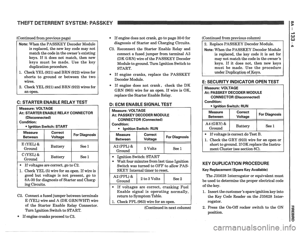
Continued from previous page)
Note: VVhen the PASSKEY Decoder Module
is replaced, the new key code may not
match the code in the owner's existing
keys. If it does not match, then new
keys must be made. Use the key
duplication procedure.
1. Check YEL (921) and BRN (922) wires for
shorts to ground or between the two
wires.
2. Check
UEL (921) and BRN (922) wires for
an open. If
engine does not crank, go to page 30-0 for
diagnosis of Starter and Charging Circuits.
C3. Reconnect the Starter Enable Relay and
connect a fused jumper from terminal A3
(DK GRN) wire of the PASSKEY Decoder
Module to ground. Ignition Switch to
START.
0 If engine cranks, replace the PASSKEY
Decoder Module.
If engine does not crank, check the DK
GRN (965) wire for
an open. If wire is OK,
replace the Starter Enable Relay.
6: STARTER ENABLE RELAY TEST
D: ECM ENABLE SIGNAL TEST
C2. Connect a fused jumper between terminals
Measure: VOLTAGE
At: STARTER ENABLE RELAY CONNECTOR
(Disconnected)
Condition:
0 Ignition Switch: START Measure:
VOLTAGE
At: PASSKEY DECODER MODULE
CONNECTOR (Connected)
Condition: 0 Ignition Switch: RUN
Measure
Between
&
Ground
&
Ground
Measure
Between I I For Diagnosis ( Voltage
1 I 5Volts I See 1 1
If voltages are correct, go to C2.
1. Check YEL (5) wire for an open. If wire is
good but voltage is not present, go to
8A-30 for diagnosis of Starter and Charg-
ing Circuits.
Correct
Voltage
Battery
Battery
I I
Ignition Switch: START
For Diagnosis
See 1
See 1
0 wait four minutes from last time Ignition
Switch was turned to OFF to
allow PAS-
SKEY Internal timer to reset.
I A2 IPPL)& ) 2 to3Volts I See2 i Ground
If voltages are correct, cranking Fuel
Enable signal is operating normally,
return to Symptom Table.
E (YEL) Vfire and A (DK GR wire 1 1. Check PPL (963) wire for an open. A of the Starter Enable Relay Connector. I I
(Continued in next column)
Ignition Switch to START.
If engine cranks proceed to
63.
Continued from previous column)
2. Replace PASSKEY Decoder Module.
Note: When the PASSKEY Decoder Module
is replaced, the key code
it is set for
may not match the code in the owner's
keys. If
it does not, then new keys
must be made. Use the procedure
under
Duplicgti~n of-Keys2
E: SECURITY INDICATOR OPEN TEST
CONNECTOR (Disconnected)
Condition:
KEY DUPLICATION PROCEDURE
Key Replacement (Spare Key Available)
The 535628 Interrogator or equivalent must
be used to det e
the proper electrical code
of the key.
1. Insert the customer's spare ignition key into
the Key Code Reader on the 535628 Inter-
rogator.
2. Press the On-Off rocker switch to the ON
position.
Page 1516 of 1825
THEFT DETERRENT SYSTEM: PASSKEY
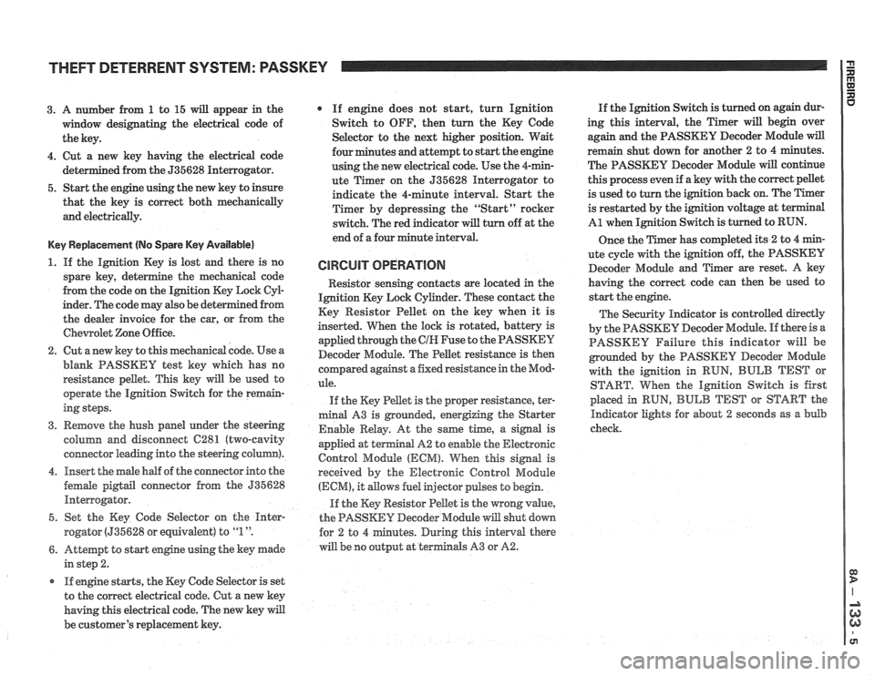
3. A number from 1 to 15 will appear in the
window designating the electrical code of
the key.
4. Cut a new key having the electrical code
ed from the 535628 Interrogator.
5. Start the engine using the new key to insure
that the key is correct both mechanically
and electrically.
Key Replacement (No Spare Key Available)
1. If the Ignition Key is lost and there is no
spare key, determine the mechanical code
from the code on the Ignition Key Lock
CyE
inder. The code may also be det
the dealer invoice for the car, or from the
Chewolet Zone Office.
2. Cut anew key to this mechanical code. Use a
blank PASSKEY test key which has no
resistance pellet. This key will be used to
operate the Ignition Switch for the remain-
ing steps.
3. Remove the hush panel under the steering
column and disconnect
C281 (two-cavity
connector leading into the steering column).
4. Insert the male half of the connector into the
female
pigtail connector from the 535628
Interrogator.
5. Set the Key Code Selector on the
Hnter-
rogator (535628 or equivalent) to "1 ".
6. Attempt to start engine using the key made
in step 2.
r If engine starts, the Key Code Selector is set
to the correct electrical code. Cut a new key
having this electrical code. The new key will
be customer's replacement key.
If engine does not start, turn Ignition
Switch to OFF, then turn the Key Code
Selector to the next higher position. Wait
four minutes and attempt to start the engine
using the new electrical code. Use the 4-min-
ute Timer on the 535628 Interrogator to
indicate the 4-minute interval. Start the
Timer by depressing the "Start" rocker
switch. The red indicator
will turn off at the
end of a four minute interval.
CIRCUIT OPERATION
Resistor senshg contacts are located in the
Ignition Key Lock Cylinder. These contact the
Key Resistor Pellet on the key when it is
inserted. When the lock is rotated, battery is
applied through the
CIH Fuse to the PASSKEY
Decoder Module. The Pellet resistance is then
colnpared against a fixed resistance in the Mod-
ule.
If the Key Pellet is the proper resistance, ter-
minal A3 is grounded, energizing the Starter
Enable Relay. At the
same time, a signal is
appfied at terminal A2 to enable the Electronic
Control Module
(ECM). When this signal is
received by the Electronic Control Module
(ECM), it allows fuel injector pulses to begin.
If the Key Resistor Pellet is the wrong
value,
the PASSKEY Decoder Module will shut down
tes. During this interval there
will be no output at terminals A3 or
A2.
If the Ignition Switch is turned on again dur-
ing this interval, the Timer will begin over
again and the PASSKEY Decoder Module
will
remain shut down for another 2 to 4 minutes.
The PASSKEY Decoder Module will continue
this process even if a key with the correct pellet
is used to turn the ignition back on. The Timer
is restarted by the ignition voltage at
t
A1 when Ignition Switch is turned to RUN.
Once the Timer has completed its
2 to 4 min-
ute cycle with the ignition off, the PASSKEY
Decoder Module and Timer are reset. A key
having the correct code can then be used to
start the engine.
The Security Indicator is controlled directly
by the PASSKEY Decoder Module. If there is a
PASSKEY Failure this indicator will be
grounded by the PASSKEY
Decoder Module
with the ignition in RUN,
BULB TEST or
START. When the Ignition Switch is first
placed in
RUN, BULB TEST or START the
Indicator lights for about 2 seconds as a bulb
check.
Page 1639 of 1825
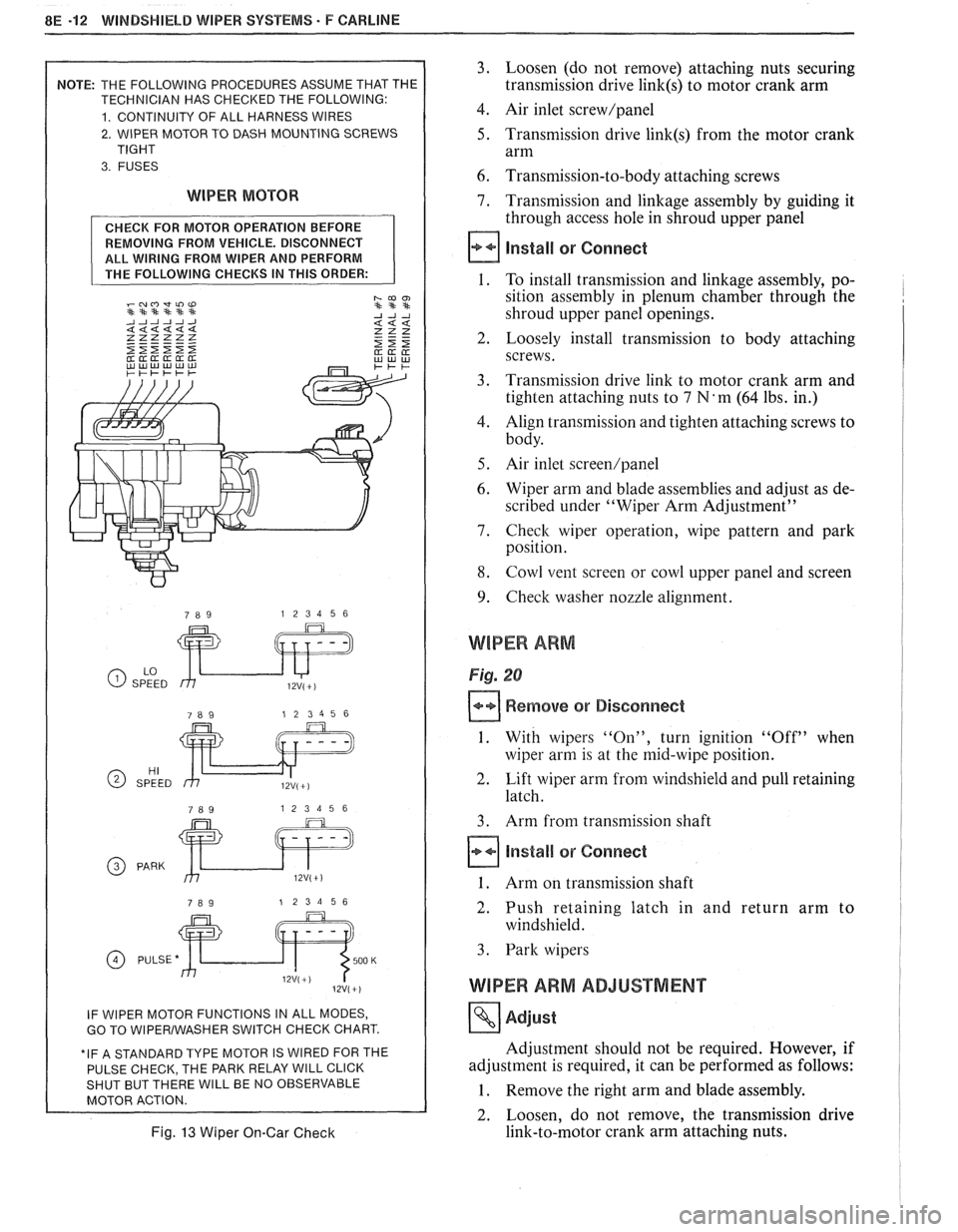
8E -12 WINDSHIELD WIPER SYSTEMS. F CAWLINE
2. WIPER MOTOR TO DASH MOUNTING SCREWS
WIPER MOTOR
REMOVING FROM VEHICLE. DISCONNECT
ALL WIRING FROM WIPER AND PERFORM
GO TO WlPERlWASHER SWITCH CHECK CHART.
E PARK RELAY
WlLL CLICK WlLL BE NO OBSERVABLE
Fig. 13 Wiper On-Gar Check
3. Loosen (do not remove) attaching nuts securing
transmission drive
link(s) to motor crank arm
4. Air inlet screw/panel
5. Transmission drive link(s) from the motor crank
arm
6. Transmission-to-body attaching screws
7. Transmission and linkage assembly by guiding it
through access hole in shroud upper panel
install or Connect
1. To install transmission and linkage assembly, po-
sition assembly in plenum chamber through the
shroud upper panel openings.
2. Loosely install transmission to body attaching
screws.
3. Transmission drive link to motor crank arm and
tighten attaching nuts to
7 N'm (64 lbs. in.)
4. Align transmission and tighten attaching screws to
body.
5. Air inlet screen/panel
6. Wiper arm and blade assemblies and adjust as de-
scribed under "Wiper Arm Adjustment"
7. Check wiper operation, wipe pattern and park
position.
8. Cowl vent screen or cowl upper panel and screen
9. Check washer nozzle alignment.
WIPER ARM
Fig. 20
Remove or Disconnect
1. With wipers "On", turn ignition "Off" when
wiper arm is at the mid-wipe position.
2. Lift wiper arm from windshield and pull retaining
latch.
3. Arm from transmission shaft
Install or Connect
1. Arm on transmission shaft
2. Push retaining latch in and return arm to
windshield.
3. Park wipers
WIPER ARM ADJUSTMENT
Adjust
Adjustment should not be required. However, if
adjustment is required, it can be performed as follows:
1. Remove the right arm and blade assembly.
2. Loosen, do not remove, the transmission drive
link-to-motor crank arm attaching nuts.