1988 PONTIAC FIERO ECU
[x] Cancel search: ECUPage 424 of 1825
ENGINE COOLING 6B-13
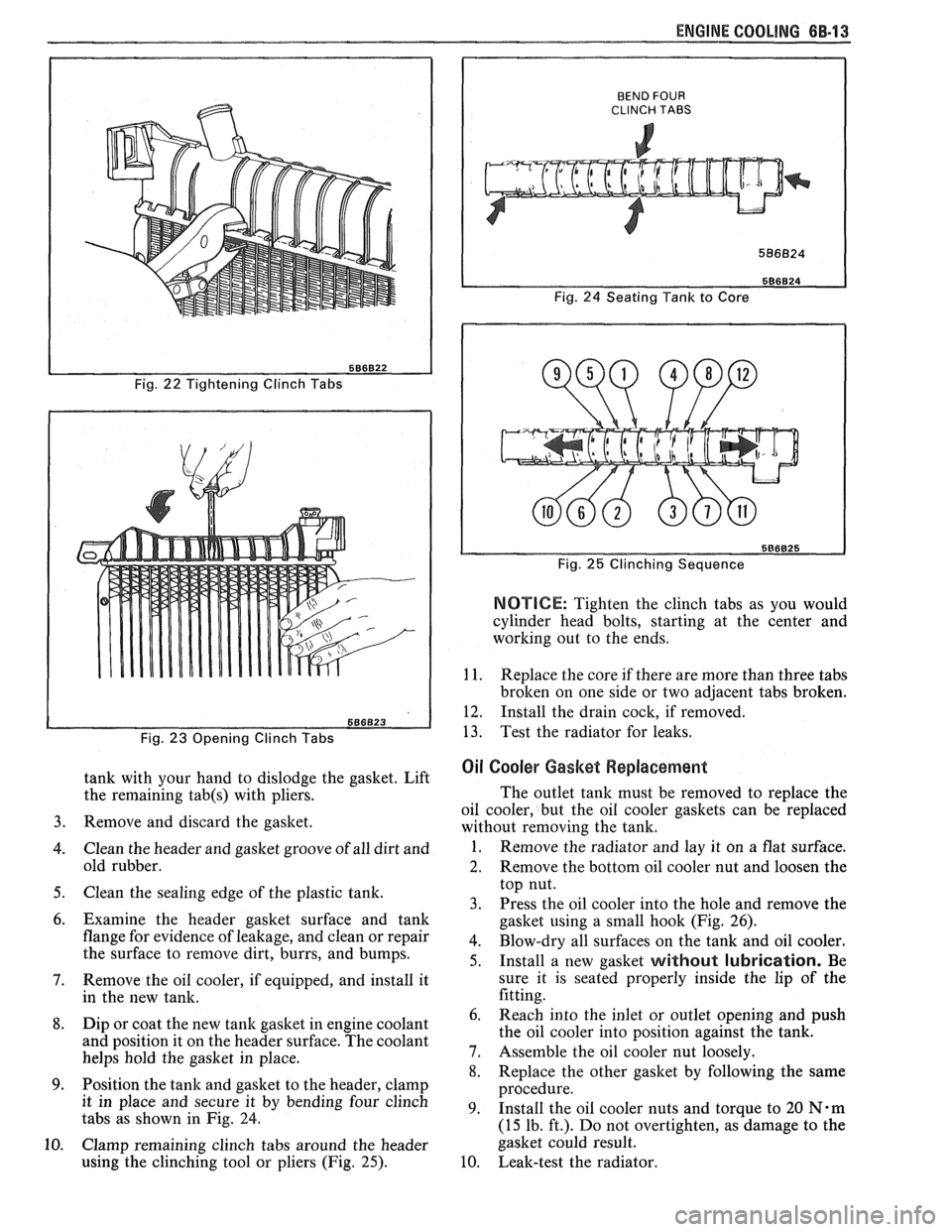
Fig. 22 Tightening Clinch Tabs
Fig.
23 Opening Clinch Tabs
tank with your hand to dislodge the gasket. Lift
the remaining
tab(s) with pliers.
Remove and discard the gasket.
Clean the header and gasket groove of all dirt and
old rubber.
Clean the sealing edge of the plastic tank.
Examine the header gasket surface and tank
flange for evidence of leakage, and clean or repair
the surface to remove dirt, burrs, and bumps.
Remove the oil cooler, if equipped, and install it
in the new tank.
Dip or coat the new
tank gasket in engine coolant
and position it on the header surface. The coolant
helps hold the gasket in place.
Position the tank and gasket to the header, clamp
it in place and secure it by bending four clinch
tabs as shown
in Fig. 24.
Clamp remaining clinch tabs around the header
using the clinching tool or pliers (Fig.
25).
BEND FOUR CLINCH TABS
Fig. 24 Seating Tank to Core
Fig.
25 Clinching Sequence
NOTICE: Tighten the clinch tabs as you would
cylinder head bolts, starting at the center and
working out to the ends.
1 1. Replace the core if there are more than three tabs
broken on one side or two adjacent tabs broken.
12. Install the drain cock, if removed.
13. Test the radiator for leaks.
Oil Cooler Gasket Replacement
The outlet tank must be removed to replace the
oil cooler, but the oil cooler gaskets can be replaced
without removing the tank.
1. Remove the radiator and lay it on a flat surface.
2. Remove the bottom oil cooler nut and loosen the
top nut.
3. Press the oil cooler into the hole and remove the
gasket using a small hook (Fig. 26).
4. Blow-dry all surfaces on the tank and oil cooler.
5. Install a new gasket without lubrication. Be
sure it is seated properly inside the lip of the
fitting.
Reach into the inlet or outlet opening and push
the oil cooler into position against the tank.
Assemble the oil cooler nut loosely.
Replace the other gasket by following the same
procedure.
Install the oil cooler nuts and torque to
20 N.m
(15 lb. ft.). Do not overtighten, as damage to the
gasket could result.
Leak-test the radiator.
Page 428 of 1825
ENGINE COOLING 68.17
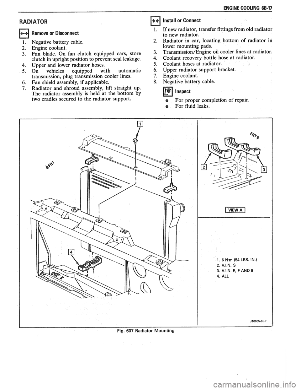
RADIATOR
Remove or Disconnect
1. Negative battery cable.
2. Engine coolant.
3. Fan blade. On fan clutch equipped cars, store
clutch in upright position to prevent seal leakage.
4. Upper and lower radiator hoses.
5. On vehicles equipped with automatic
transmission, plug transmission cooler lines.
6. Fan shield assembly, if applicable.
7. Radiator and shroud assembly, lift straight up.
The radiator assembly is held at the bottom by
two cradles secured to the radiator support.
Install or Connect
1. If new radiator, transfer fittings from old radiator
to new radiator.
Radiator in car, locating bottom of radiator in
lower mounting pads.
Transmission/Engine oil cooler lines at radiator.
Coolant recovery bottle hose at radiator.
Coolant hoses at radiator.
6. Upper radiator support bracket.
7. Engine coolant.
8. Negative battery cable.
Inspect -
e For proper completion of repair.
e For fluid leaks.
Page 434 of 1825
ENGINE FUEL 6C.3
a Fuel feed and return pipes are secured to the
underbody with clamps and screw assemblies.
The pipes should be inspected occasionally for
leaks, kinks or dents.
e Follow the same routing as the original pipe.
e Pipes must be properly secured to the frame to
prevent chafing. A minimum of 6 mm
(1/4")
clearance must be maintained around a pipe to
prevent contact and chafing.
MPFl Fuel Pipes
Due to the fact that fuel pipes are under high
pressure, these systems require special consideration for service.
Many feed and return pipes use screw couplings
with
"0" Rings. Any time these fittings are loosened
to service or replace components, ensure that:
a A backup wrench is used while loosening and
tightening the fitting.
e Check all "0" rings at fitting locations (if
applicable) for cuts or any damage and replace
any that appear worn or damaged.
e Use correct torque when tightening fittings.
If pipes are replaced always use original
equipment parts, or parts that meet GM
specifications.
Fuel and Vapor Hoses
NOTICE: Fuel and vapor hoses are specially
manufactured. If replacement becomes necessary,
it is important to use only replacement hoses
meeting GM Specification 6163-M. These hoses
are identified with the words "Fluoroelastomer"
on them. Hoses not so marked could cause early
failure, or fail to meet emission standards.
e Do not use rubber hose within 4" of any part of
the exhaust system, or within
10" of the catalytic
converter.
FUEL PUMP
The electric fuel pump is in the fuel tank. The
tank has an outlet for a vapor return system. Any vapor
which forms is returned to the fuel tank along with hot
fuel through a separate line. This greatly reduces any
possibility of vapor lock by keeping cool fuel from the
tank constantly circulating through the fuel pump.
FUEL PUMP RELAY
To control fuel pump operation, a fuel pump
relay is used.
When the ignition switch is turned to "RUN"
position, the fuel pump relay activates the electric fuel
pump for
1.5 to 2.0 seconds to prime the injector(s). If
the ECM does not receive reference pulses from the
distributor after this time, the ECM signals the relay
to turn off the fuel pump. The relay will once again
activate the fuel pump when the
ECM receives
distributor reference pulses.
Fuel Filter
CAUTION: To reduce the risk of fire
and personal injury, it is necessary
to
relieve the fuel system pressure
before servicing fuel system
components. (See Fuel System
Pressure Relief.)
The inline filters can be found on the rear
crossmember of the vehicle. Always use a backup
wrench any time that the fuel filter is removed or
installed. Also make sure that a good
"0" Ring is used
at all screw couple locations. Torque on fittings is
30
N-m (22 lb. ft.).
FUEL TANK
The fuel tank is usually located under the rear of
the vehicle and a number of shapes and sizes are used
depending on the application.
The tank is held in place by two metal straps,
hinged (with a bolt through the hinge) and secured at
the opposite end with a nut and bolt assembly.
Anti-squeak pieces are used on top of the tank to
reduce rattles and other annoying noises.
The fuel tank, cap and lines should be inspected
for road damage, whch could cause leakage. Inspect
fuel cap for correct sealing and indications of physical
damage. Replace any damaged or malfunctioning
parts.
Before attempting service of any type on the fuel
tank, always
(1) remove negative battery cable from
battery, (2) place "no smoking" signs near work areas,
(3) be sure to have C02 fire extinguisher handy, (4)
wear safety glasses and
(5) siphon or pump fuel into an
explosion proof container.
Fuel Filler Gap
The fuel tank filler neck is equipped with a
screw-type cap. The threaded part of the cap requires
several turns counterclockwise to remove. The long
threaded area is designed to allow any remaining fuel
tank pressure to escape while the cap is being removed.
A built-in torque-limiting device prevents
overtightening. To install, turn the cap clockwise until
a clicking noise is heard. This signals that the correct
torque has been reached and the cap is fully seated.
N OTI G E: If a fuel filler cap requires replacement,
use only a cap with the same features. Failure to
use the correct cap can result in a serious
malfunction of the system.
Available on some models is an electric locking
fuel filler cap. Information on this option will be found
in Section
9E.
FUEL TANK FILLER NECK
To help prevent refueling with leaded gasoline,
the fuel filler neck on gasoline engine cars has a built-in
restrictor and deflector. The opening in the restrictor
will only admit the smaller unleaded gas nozzle spout,
which must be fully inserted to bypass the deflector.
Attempted refueling with a leaded gas nozzle or failure
Page 435 of 1825

6C-4 ENGINE FUEL
to fully insert the unleaded gas nozzle will result in
gasoline splashing back out of the filler neck.
Fuel Gage Sending Unit
The fuel gage sending unit is attached to the top
of the fuel tank. It is held in place with a cam lock ring
and a gasket is used between the tank and sending unit.
Sending units have three hoses attached. One line
is for the fuel feed. The second line is connected to the
vapor canister, to keep fuel vapor from getting into the
air (see Section 6E). The third line is used as a fuel
return line to the tank.
On some sending units a wire is attached to the
unit. On others the connectors attach directly to the
sender.
When a fuel gage sending unit is removed always
make sure to install the gasket and any power or
ground leads that were removed.
DIAGNOSIS
Fuel system diagnostic procedures are located in
Section(s) 6E1 thru 6E3.
SERVICE PROCEDURES
If the fuel system is suspected of delivering an
improper amount of fuel, it should be inspected and
tested in the vehicle, as follows:
1. Make certain that there is fuel in the tank.
2. With the engine running, inspect for leaks at all
fuel feed pipe and hose connections from
fuel
tank to injection pump. Tighten any loose
connections. Inspect all hoses for flattening or
kinks which would restrict the flow of fuel. Air
leaks or restrictions on suction side of fuel pump
will seriously affect pump output.
FUEL SYSTEM PRESSURE RELIEF
CAUTION: To reduce risk of fire and
personal injury, it is necessary to
relieve duel system pressure before
servicing fuel system components. To
do this:
Remove "fuel pump" fuse from fuse
block in passenger compartment.
e Crank engine - engine will start and run
until fuel supply remaining in fuel lines is
consumed. Engage starter for
3.0
seconds to assure relief of any remaining
pressure.
e With ignition "OFF", replace duel pump
fuse.
Unless this procedure
is followed before
servicing fuel lines
or connections, fuel
spray could occur.
When repair to the fuel system has been
completed, start engine and check all connections that
were loosened for possible leaks.
Refer to Section 6E for additional diagnosis of
engine fuel system.
Fuel Pump Flow Test
1. Test fuel
pump by connecting hose from EFI fuel
feed line to a suitable unbreakable container.
Apply battery voltage to the fuel pump test
terminal (terminal
"G" of ALCL).
2. Fuel pump should supply
1/2 pint or more in 15
seconds.
3. If flow is below minimum, check for fuel
restriction. If there is no restriction, check pump
pressure.
Fuel System Pressure Test
This test must be performed when diagnosing the
fuel system.
CAUTION: To reduce the risk of fire
and personal injury, it is necessary to
relieve fuel system pressure before
servicing fuel system components on
the
TBI system. To do this:
s Remove "Fuel Pump" fuse from fuse block in
passenger compartment.
e Crank engine. Engine will start and run until fuel
remaining in fuel lines is consumed. Crank the
starter for three seconds to assure that any
remaining pressure is relieved.
e With the ignition off, replace the "Fuel Pump"
fuse.
1. Obtain two
sections of
3/8" steel tubing. Each
should be about 254 mm (10 inches) long.
I
Double-flare one end of each section.
2. Install a flare nut on each section. Connect each i
of the above sections of tubing into the "flare nut 1
to flare nut adapters" that are included in J-29658 i
Gage Adapters.
3. Attach the
pipe and adapter assemblies to the
J-29658 gage.
4. Hoist the car.
5. Disconnect
front fuel feed hose from the fuel pipe
on the body.
1
6. Install a
254 mm (10 inch) length of 3/8" fuel
hose onto the fuel feed pipe on the body. Attach 1
I the other end of the hose onto one of the sections
of pipe mentioned in Step 1. Secure the hose
connections with clamps.
7. Attach the front fuel feed hose onto the other
i
section of tubing mentioned in Step 1. Secure the I
hose connection with a clamp. I
8. Start
the engine and check for leaks. I 9. Observe
the fuel pressure reading. It should be 62
to 90
kPa (9 to 13 psi). If not, refer to the I
appropriate Emissions Section.
10. Depressurize
the fuel system and remove the gage I
with adapters. Reconnect the fuel feed hose to the
pipe and torque the clamp to
1.7 N.m (1 5 lb. in.).
11. Lower
the car. Start the engine and check for fuel
leaks.
Fuel System Pressure Test- MPFl
Fuel system diagnosis is in Section 6E3, Chart
A-7.
Page 437 of 1825
86-8 ENGINE FUEL
Fuel Tank Leak Test Procedure
Plug all outlets. Before removing a fuel tank for
a suspected fuel leak, make sure that it is not one of the
fuel hoses that is leaking onto the tank.
On-Car Test
If fuel is leaking from tank, replace tank.
Off-Car Pest
Apply a small amount of air pressure to tank
through vent tube (approximately
7 to 10 kPa or 1 to
1-1/2 lbs. of pressure).
NOTICE: More than 1-1/2 pounds of pressure
will damage tank permanently.
Test repaired area for leaks with soap solution, or
by submersion. If leak is noted, replace tank.
ACCELERATOR CONTROLS
The accelerator control system is cable type.
There are no linkage adjustments.
As there are no adjustments, the specific cable for
each application must be used. Only the specific
replacement part will work.
When work has been performed on accelerator
controls, always check to ensure that all components
are installed as removed and that all linkage and cables
are not rubbing or binding in any manner.
Accelerator Control Cable
Refer to On-Car Service for removal and
installation of accelerator control cable.
When performing service on the accelerator
control cable, observe the following:
s Retainer must be installed with tangs secured
over head of stud.
s Conduit fitting at both ends of cable must have
locking tangs expanded and locked in attaching
holes.
s The braided portion of the accelerator cable
assembly must not come in contact with the front
of dash sealer during assembly, repair or
replacement of the assembly.
e Flexible components (hoses, wires, conduits, etc.)
must be routed within
50.0mm (2.0 in.) of moving
parts of accelerator linkage, outboard of support,
unless routing is positively controlled.
Whenever disconnecting or replacing parts, lube
pivot points with Accelerator Linkage Lubricant
1052541, or equivalent.
Accelerator Pedal
When performing service on the accelerator
pedal, observe the following:
s The mounting surface between support and dash
panel must be free of insulation. The carpet and
padding in pedal and tunnel area must be
positioned to lay flat and be free of wrinkles and
bunches.
s Slip accelerator control cable through slot in rod
and then install retainer in rod, being sure it is seated.
Care must be utilized in pressing the
retainer into hole in rod, to assure the cable is not
kinked or damaged in any way.
s After securing all components of the accelerator
linkage, linkage must operate freely, without
binding, between full closed throttle and full wide
open throttle.
e Wire, hoses, cables or other obstructions must
not be placed within 13mm
(33/64 in.) of cable
or rod at any point in their travel.
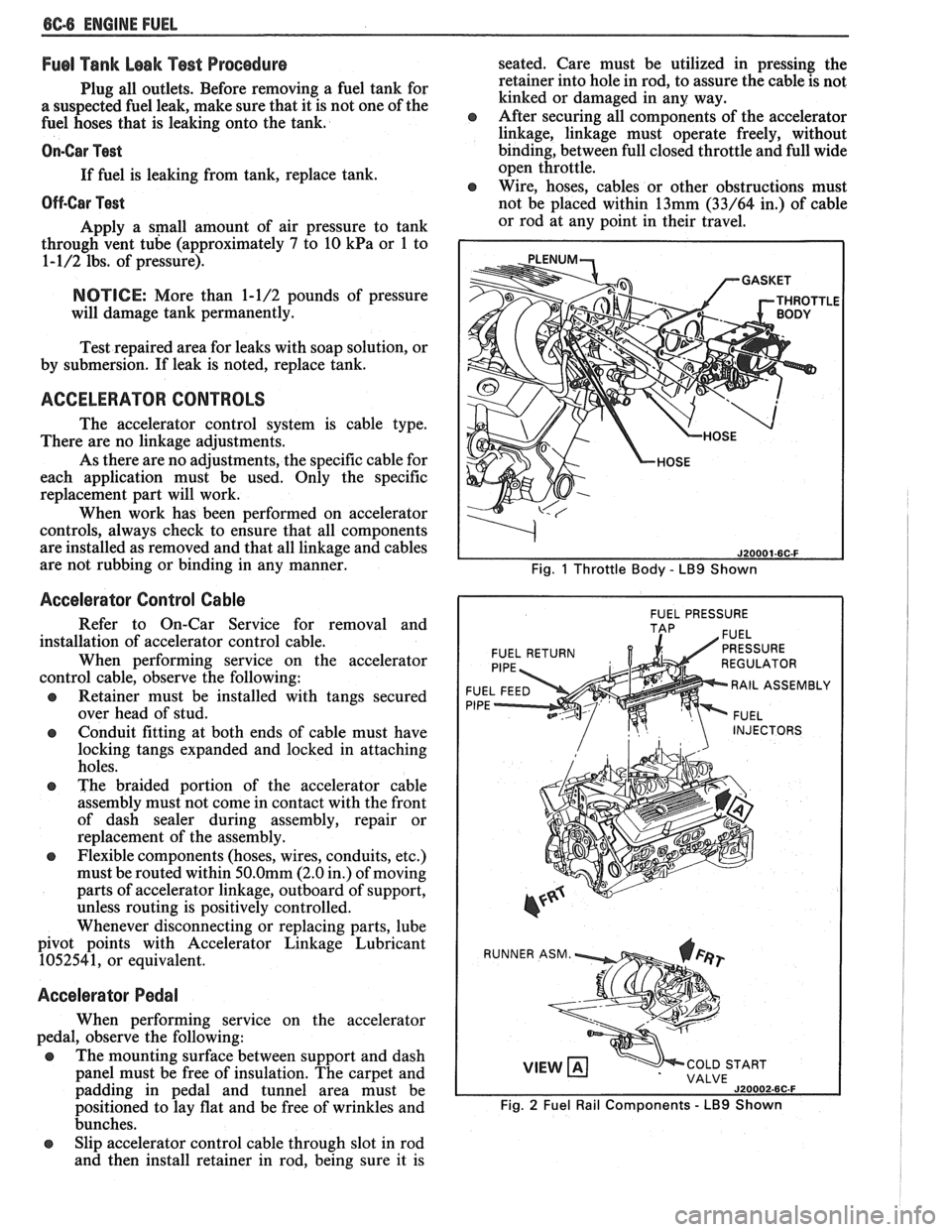
Fig. 1 Throttle Body - LB9 Shown
I FUEL PRESSURE I
FUEL RETURN
F
RAIL ASSEMBL
P
INJECTORS
VIEW COLD START
VALVE
J20002-6C-F
Fig. 2 Fuel Rail Components - LB9 Shown
Page 445 of 1825
6D1-2 BA'TTERY
3. The
vehicle's electrical load is more than the
generator output, particularly with the addition
of aftermarket equipment.
4. Defects in the charging system such as electrical
shorts, slipping fan belt, faulty generator, or
faulty voltage regulator.
5. Battery abuse, including failure to keep the
battery cable terminals clean and tight, or loose
battery hold-down. See "Service Procedures" for
torque specifications.
6. Mechanical problems in the electrical system,
such as shorted or pinched wires.
Electrolyte Freezing
The freezing point of electrolyte depends on its
specific gravity. Since freezing may ruin a battery, it
should be protected against freezing by keeping it in a
charged condition.
Carrier and Hold-Down
The battery carrier and hold-down clamp should
be clean and free from corrosion before installing
battery.
The carrier should be in sound condition, to hold
the battery securely and keep it level. Make certain
there are no parts in the carrier before installing
battery.
To prevent the battery from shaking
in its carrier,
the hold-down bolts should be tight, but not
overtightened.
Built-In Hydrometer
The sealed battery has a built-in, temperature
compensated hydrometer in the top of the battery. This
hydrometer is to be used with the following diagnostic
procedure.
When observing the hydrometer, make sure that
the battery has a clean top. A light may be required,
if the lighting is poor.
Under normal operation, two indications can be
observed (see Fig.
4).
1. GREEN DOT VISIBLE
Any green appearance is interpreted as a "green
dot" and the battery
is ready for testing.
2. DARK; GREEN DOT NOT VISIBLE
If there is a cranking complaint, the battery
should be tested as described in the "Diagnosis"
section. The charging and electrical system
should also be checked at this time.
Occasionally, a third condition may appear:
3. CLEAR OR LIGHT YELLOW
This means the fluid level is below the bottom of
the hydrometer. This may have been caused by
excessive or prolonged charging, a broken case,
excessive tipping, or normal battery
wearout.
Finding a battery in this condition may indicate
high charging voltages caused by a faulty
charging system. Therefore, the charging and
electrical systems may need to be checked. If a
cranking complaint exists and is caused by the
battery, it should be replaced.
BATTERY
1. VISUAL INSPECTION
Check for obvious damage, such as cracked or
broken case or cover, that could permit loss of
electrolyte. If obvious damage is noted, replace
the battery. Determine cause of damage and
correct as needed. If not, proceed to step 2.
2. HYDROMETER CHECK
a. GREEN
DOT VISIBLE
- Go To Step 3
b. DARK;
GREEN DOT NOT VISIBLE -
Charge the battery as outlined under
"Charging Procedure" section and proceed
to Step 3.
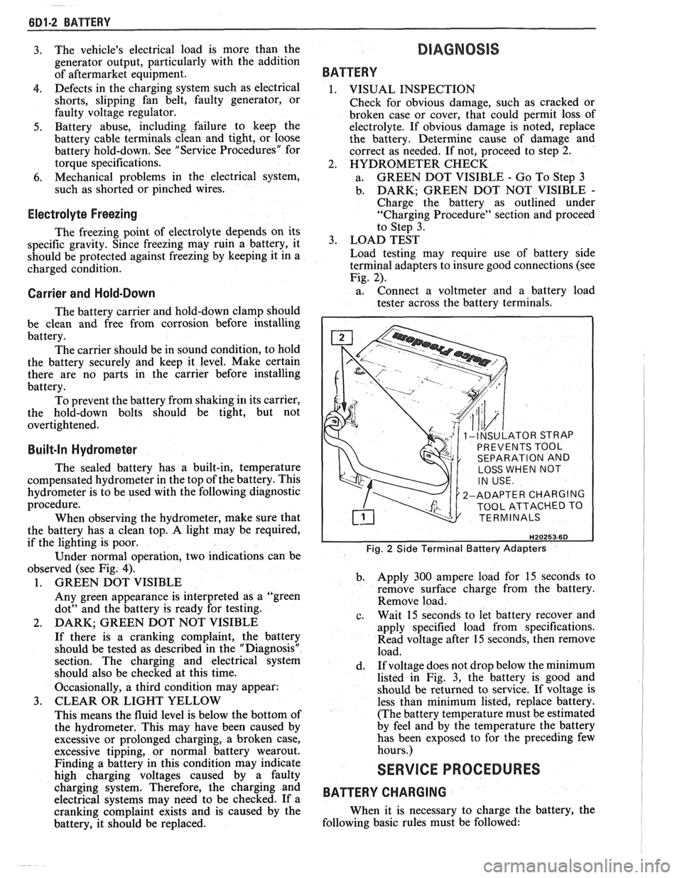
3. LOAD TEST
Load testing may require use of battery side
terminal adapters to insure good connections (see
Fig. 2).
a. Connect
a voltmeter and a battery load
tester across the battery terminals.
INSULATOR STRAP
PREVENTS TOOL
SEPARATION AND
LOSS WHEN NOT
2-ADAPTER CHARGING
TOOL ATTACHED TO
TERMINALS
Fig. 2 Side Terminal Battery Adapters
b. Apply 300 ampere load for 15 seconds
to
remove surface charge from the battery.
Remove load.
c. Wait
15 seconds to let battery recover and
apply specified load from specifications.
Read voltage after 15 seconds, then remove
load.
d. If
voltage does not drop below the minimum
listed in Fig. 3, the battery is good and
should be returned to service. If voltage is
less than minimum listed, replace battery.
(The battery temperature must be estimated
by feel and by the temperature the battery
has been exposed to for the preceding few
hours.)
SERVICE PROCEDURES
BATTERY CHARGING
When it is necessary to charge the battery, the
following basic rules must be followed:
Page 461 of 1825
6D2-10 CRANKING SYSTEM
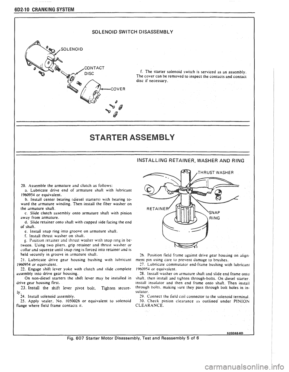
SOLENOID SWITCH DISASSEMBLY
I
COVER
3
f. The starter solenoid switch is servlced as an assembly.
The cover can be removed to Inspect the contacts and contact dlsc rf necessary.
STARTER ASSEMBLY
INSTALLING RETAINER, WASHER AND RING
1 THRUST WASHER
I 20. Assemble the armature and clutch as follows:
a. Lubricate dnve end of armature shaft w~th lubricant
1960954 or equ~valent. b. Install center bearrng (dresel starters) wrth bear~ng to-
ward the armature w~nd~ng. Then install the fiber washer on
the armature shaft
c Slide clutch assembly onto armature shaft
w~th plnlon dwdy from armature.
d. Sllde retainer onto shaft w~th cupped 51de facing the end
of shaft.
e
Install snap rrng Into groove on armature >haft. f. Install thrust washer on bhaft.
g I'os~t~on retmer ~nd thrust washer with snap rlng in be-
tween Usrng two pl~ers, gnp retalner ~nd thrust washer or sollar and bqueeze unt~l snap rrng 15 forced Into retainer and 15 held becurely In groove rn ,
mature shaft. 26 Po5111on field frame agarnst drrve gear houb~ng on alrgn 21. Lubr~cate dr~ve gear housrng bush~ng w~th lubricant ment pln uslng care to prevent damage to brushes.
1960954 or equtvalent. 27 Lubrrcate commutator end-frame bush~ng wrth lubncan~ 22. Engage shift lever yoke w~th clutch and jlrde complete 1960954 or equ~vnlent assembly Into dnve gear houb~ng. 28 Install washer on armature >haft and sl~de end frame onto
On non-diesel starters the sh~ft lever may be ~nslalled In \haft, then ~nstall and t~ghten through-bolts. On d~esel starter
drrve gear houslng first. ~nstall ~nsulator and then end frame onto shaft. Then ~nstall
23. Install the shift lever p~vot bolt. Tighten secure. through bolts. maklng jure they pass through bolt holes In In-
IY. sulator
24 Install solenold assembly. 29 Connect the tirld co11 connector to the solenold term~nal 25. Apply \ealrr. No. 1050026 or equ~valent to bolenold 30. Check plnron clearance ,I> outi~ned under PlNlOh flange where field frame contacts 11. CLEARANCE.
520046.6D
Fig. 607 Starter Motor Disassembly, Test and Reassembly 5 of 6
Page 469 of 1825
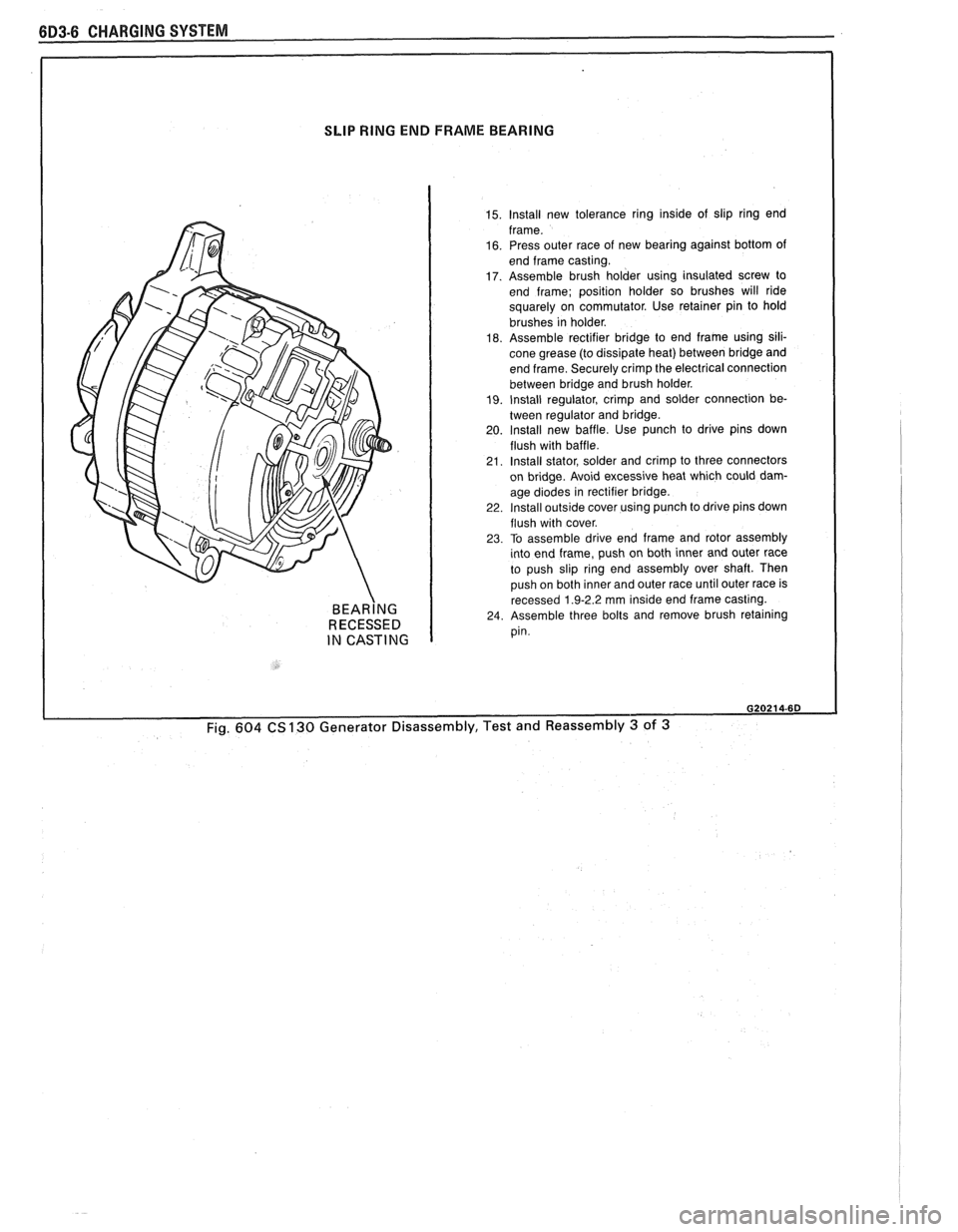
SLIP RING END FRAME BEARING
BEAR~NG RECESSED
IN CASTING
15. lnstall new tolerance ring inside of slip ring end
frame.
16. Press outer race of new bearing against bottom of
end frame casting.
17. Assemble brush holder using insulated screw to
end frame; position holder so brushes will ride
squarely on commutator. Use retainer pin to hold
brushes in holder.
18. Assemble rectifier bridge to end frame using sili-
cone grease (to dissipate heat) between bridge and
end frame. Securely crimp the electrical connection
between bridge and brush holder.
19. Install regulator, crimp and solder connection be-
tween regulator and bridge.
20. lnstall new baffle. Use punch to drive pins down
flush with baffle.
21. Install stator, solder and crimp to three connectors
on bridge. Avoid excessive heat which could dam-
age
d~odes In rect~f~er br~dge 22 Install outsrde cover uslng punch to drlve plns down
flush w~th cover
23 To assemble drlve end frame and rotor assembly tnto end frame, push on both Inner and outer race
to push
slrp rlng end assembly over shaft Then
push on both
Inner and outer race untll outer race IS recessed 1 9-2 2 mm lns~de end frame castrng 24 Assemble three bolts and remove brush retalnlng pin.
020214-6D
Fig. 604 CS 130 Generator Disassembly, Test and Reassembly 3 of 3