1988 PONTIAC FIERO ECU
[x] Cancel search: ECUPage 851 of 1825
6E3-A-48 5.OL (VIN F) & 5.7L (VIN 8) DRIVEABILITY AND EMISSIONS
CODE 41
CYLINDER SELECT ERROR
(FAULTY OR INCORRECT MEM-CAL)
5.OL (VIN F) & 5.7L (VIN 8) "F" SERIES (PORT)
Test Description: Numbers below refer to circled Diagnostic Aids:
numbers on the diagnostic chart.
1. The ECM used for this engine can also be used for
Check mem-cal to be sure locking tabs are secure.
other engines, and the difference is in the Mem-
Also check the pins on both the Mem-Cal and
Cal. If a Code 41 sets, the incorrect Mem-Cal has
ECM to assure they are making proper contact. Check
been installed, may not be installed properly, or it
the Mem-Cal part number to assure it is the correct
is faulty and it must be replaced.
part. If the Mem-Cal is faulty, it must be replaced. It
is also possible that the ECM is faulty, however, it
should not be replaced until all of the above have been
checked. For additional information, refer to
"Intermittents" in Section
"H".
Page 930 of 1825
DRlVEABlLlfVAND EMISSIONS 5.OL (VIN F) & 5.7L (VIN 8) 6E3-C6-3
Hoses and Pipes
1. Hose or pipe for deterioration or holes.
2. All hoses or pipe connections, and clamp tightness.
3. Hose or pipe routing. Interference may cause
wear.
4. If
a leak is suspected on the pressure side of the
system or if a hose or pipe has been disconnected
on the pressure side, the connections should be
checked for leaks with a soapy water solution.
With the pump running, bubbles will form if a
leak exists.
Check Valve
Inspect
1. A check valve should be inspected whenever the
hose is disconnected from a check valve or
whenever check valve failure is suspected.
(A
pump that had become inoperative and had shown
indications of having exhaust gases in the pump
would indicate check valve failure).
2. Blow through the check valve (toward the cylinder
head) then attempt to suck back through the check
valve. Flow should only be in one
direction(toward the exhaust manifold). Replace
valve which does not operate properly.
ON-CAR SERVICE
DRIVE BELT
Remove or Disconnect
1. Inspect drive belt for wear, cracks or deterioration
and replace if required. When installing a new
belt, it must be seated and fully secured in grooves
of all belt driven components.
AIR INJECTION PUMP
Remove or Disconnect
1. Hold pump pulley from turning by cotnpressing
drive belt, then loosen pump pulley bolts.
2. Drive belt and pulley.
3. Hoses, vacuum, and electrical connections from
air injection control valve.
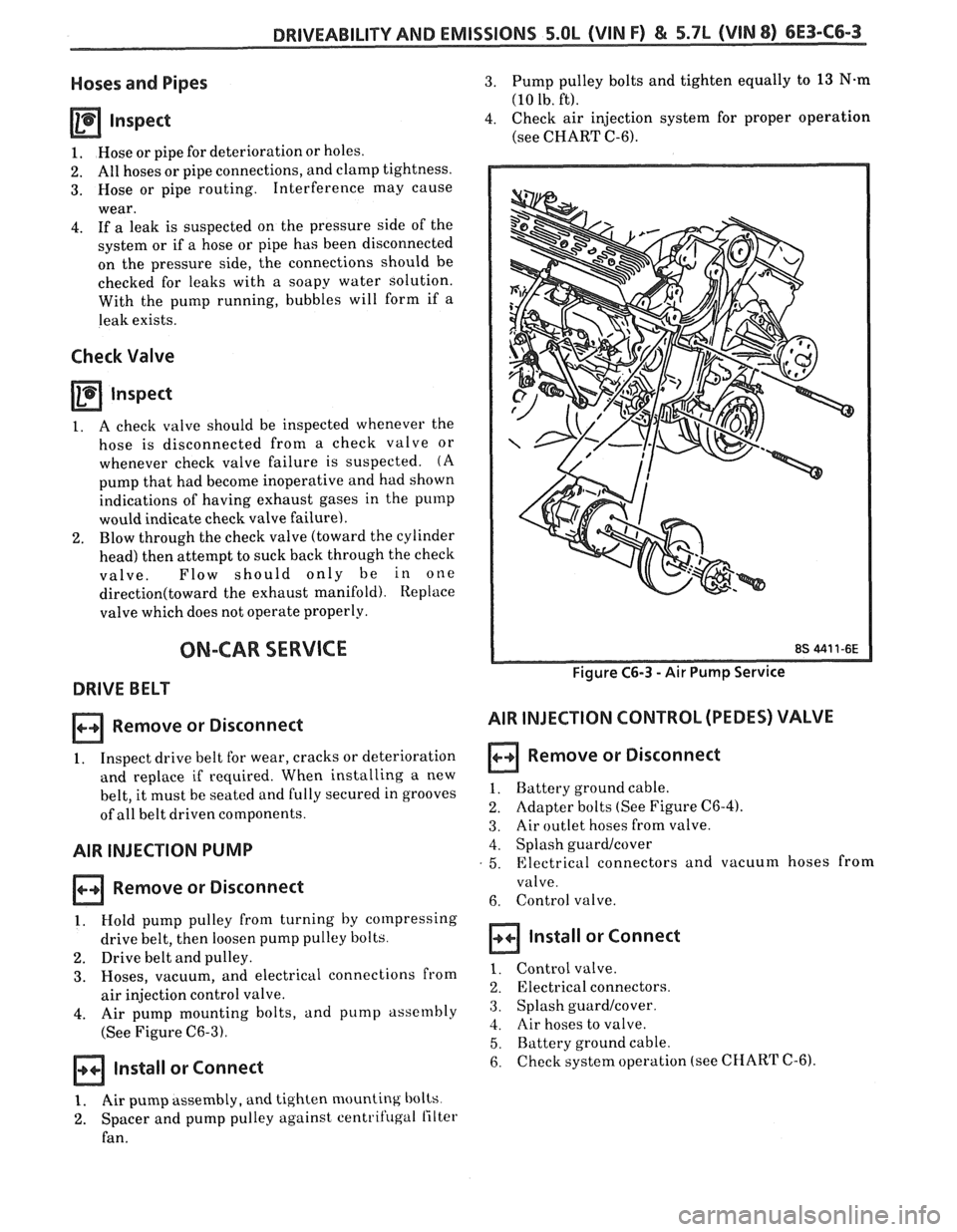
4. Air pump mounting bolts, and pump assembly
(See Figure
C6-3).
Install or Connect
3. Pump pulley bolts and tighten equally to 13 N.m
(10 lb. ft).
4. Check air injection system for proper operation
(see CHART C-6).
Figure C6-3 - Air Pump Service
AIR INJECTION CONTROL (PEDES) VALVE
Remove or Disconnect
1. Battery ground cable.
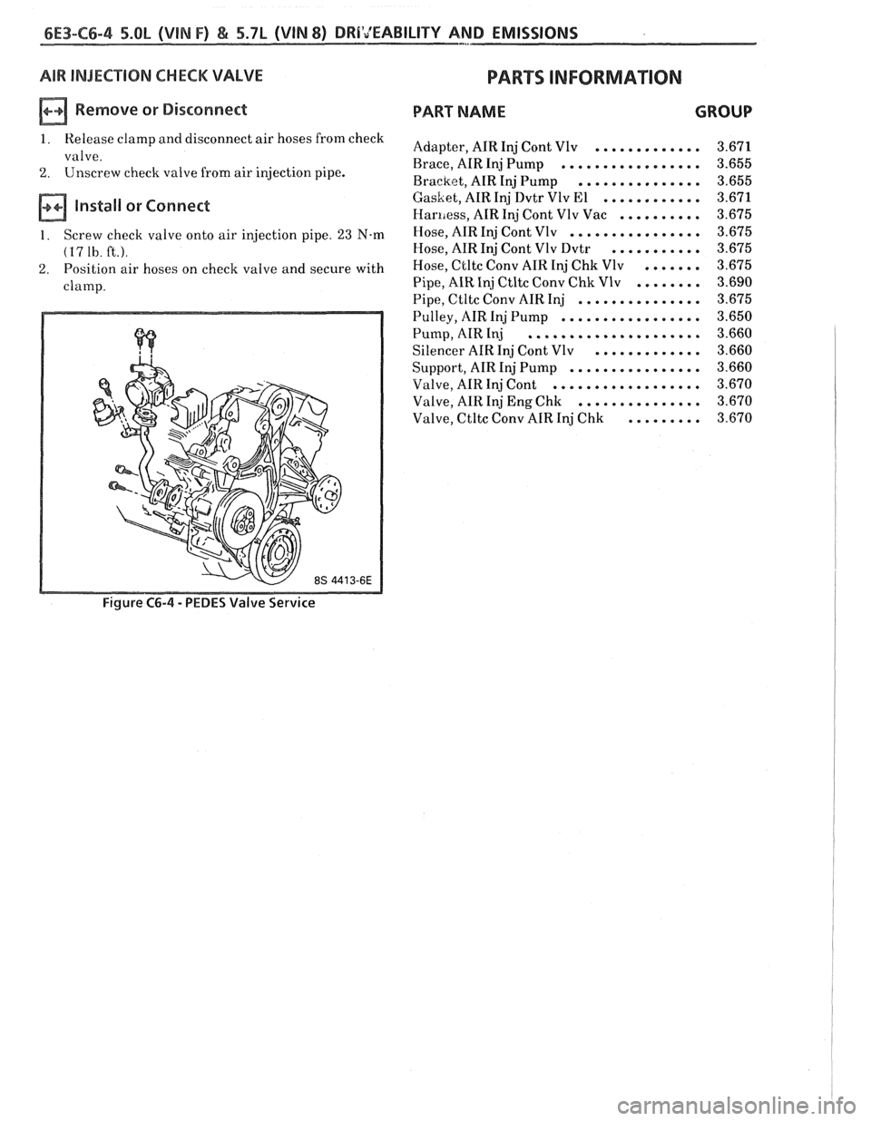
2. Adapter bolts (See Figure C6-4).
3. Air outlet hoses from valve.
4. Splash guardlcover
5. Electrical connectors and vacuum hoses from
valve.
6. Control valve.
Install or Connect
1. Control valve.
2. Electrical connectors.
3. Splash guard/cover.
4. Air hoses to valve.
5. Battery ground cable.
6. checksystem operation (see CHART C-6).
1. Air pump assembly, and tighten mounting bolts
2. Spacer and pump pulley against centrifugal lilter
fan.
Page 931 of 1825
6E3-C6-4 5.QL (VIN F) & 5.7L (WIN 8) DRI'JEABILITY AND - .. EMISSIONS
AIR INJECTION CHECK VALVE
a Remove or Disconnect
1 . Release clamp and disconnect air hoses from check
valve
.
2 . Unscrew check valve from air injection pipe .
install or Connect
1 . Screw check valve onto air injection pipe . 23 N-m
(1'7 1h . ft.).
2 . Position air hoses on check valve and secure with
clamp
.
PARTS IMF0RMA"TION
PART NAME GROUP
............. Adapter. AIR Inj Cont Vlv 3.671
Brace. AIR Inj Pump
................. 3.655
Bracket. AIR Inj Pump
............... 3.655
............ GasLet. AIR Inj Dvtr Vlv El 3.671
Haniess. AIR Inj Cont Vlv Vac .......... 3.675
................ Hose. AIR Inj Cont Vlv 3.675
Hose. AIR Inj Cont Vlv Dvtr
........... 3.675
Hose.
Ctltc Conv AIR Inj Chk Vlv ....... 3.675
........ Pipe. AIR Inj Ctltc Conv Chk Vlv 3.690
Pipe. Ctltc Conv AIR Inj
............... 3.675
................. Pulley. AIR Inj Pump 3.650
..................... Pump. AIR Inj 3.660
............. Silencer AIR Inj Cont Vlv 3.660
................ Support.
AIR Inj Pump 3.660
.................. Valve. AIR Inj Cont 3.670
............... Valve. AIR Inj Eng Chk 3.670
......... Valve.
C tltc Conv AIR Inj Chk 3.670
Figure C6-4 . PEDES Valve
Service
Page 973 of 1825
6E-12 DRIVEABILITY AND EMISSIONS - FUEL INJECUION
and MPH) for abbreviations used in this Section, but
all types are acceptable.
NA/F - AI WFUEL (NF RATIO)
A.I.R.
- AIR INJECTOR REACTION SYSTEM - Air
flow from pump is directed into engine exhaust
manifold
and/or converter to reduce exhaust
emissions.
ALDL - ASSEMBLY LINE DIAGNOSTIC LINK - Used
at assembly to evaluate Computer Command Control,
and for service to flash the "Service Engine Soon"
light
if there are trouble codes. It also is used by
"Scan" tools to obtain ECM serial data.
BARO - BAROMETRIC ABSOLUTE PRESSURE
SENSOR
- Reads atmospheric pressure.
B + - Battery Positive Terminal (12 Volts) or
system voltage with the engine running
(approximately 13.8
v.)
CALPAK - A device used with fuel injection to
allow fuel delivery in the event of a PROM or ECM
malfunction.
CALIBRATOR - (PROM) - An electronic component
that can be
specifically programmed to meet engine
operating requirements for a
specific vehicle model.
It plugs into the Engine Control Module
(ECM).
CCC - COMPUTER COMMAND CONTROL - has an
electronic control module to control airlfuel and
emission systems.
CLCC - CLOSED LOOP CARBURETOR CONTROL -
Used to describe oxygen sensor to ECM to MIC
solenoid circuit operation.
C3I - Computer Controlled Coil Ignition. Produces
the ignition spark without the aid of an ignition
distributor.
CCP - CONTROLLED CANISTER PURGE - ECM
controlled solenoid valve that permits manifold
vacuum to purge the evaporative emissions from the
charcoal canister.
CID - CUBIC INCH DISPLACEMENT - Used to
describe engine size.
UL OR ULOOP - "CLOSED LOOP" - Describes ECM
fuel control when using oxygen sensor information.
COOLANT TEMPERATURE SENSOR - Device that
senses the engine coolant temperature, and passes
that information to the engine control module.
CONV. - CATALYTIC CONVERTER, THREE-WAY -
EXHAUST CONVERTER. Containing platinum and
palladium to speed up conversion of
HC and CO, and
rhodium to accelerate conversion of NO,.
CO - CARBON MONOXIDE - One of the pollutants
found in engine exhaust.
6V - CRANKCASE VENTlhaflON - Prevents fumes
in crankcase from passing into the atmosphere, by
drawing them into the intake manifold and burning
them in the the combustion process.
DIAGNOSTIC CODE - Pair of numbers obtained
from flashing "Service Engine Soon" light or
displaying on a "Scan" tool. This code can be used to
determine the system malfunction.
DIAGNOSTIC TERM. - Lead of ALDL Connector
which is grounded to get a Trouble Code.
It is
grounded with the engine running to enter the "Field
Service Mode".
DIS - Direct Ignition System. Produces the
ignition spark without the aid of an ignition
distributor.
DVM (10 Meg.) - Digital Voltmeter with 10 Million
ohms resistance
- used for measurement in electronic
systems.
DWELL - The amount of time (recorded on a dwell
meter in degrees of crankshaft rotation) that current
passes through a closed switch; for example, ignition
contact points or internal switch in an electronic
control module.
EAC - ELECTRIC AIR CONTROL - Used on A.I.R.
system to direct air flow to air switching valve or to
atmosphere.
EAS - ELECTRIC AIR SWITCHING - used to direct air
flow to catalytic converter or exhaust ports of the
engine.
ECM - ENGINE CONTROL MODULE (ELECTRONIC) -
A metal case (located in passenger compartment)
containing electronic circuitry which electrically
controls and monitors airlfuel and emission systems
on computer command control, and turns
"ON" the
"Service Engine Soon" light when a malfunction
occurs in the system.
EFI - ELECTRONIC FUEL INJECTION - Computer
Command Control using throttle body fuel injection.
EGR - EXHAUST GAP REClRCUbATlON - Method of
reducing NO, emission levels by causing exhaust gas
to be added to airlfuel mixture in combustion
chamber, thus cooling combustion.
EECS - EVAPORATIVE EMISSIONS CONTROL
SYSTEM
- Used to prevent gasoline vapors in the fuel
tank from entering the atmosphere.
EFE - EARLY FUEL EVAPORATION - Method of
warming the intake manifold during cold engine
operation. Provides efficient airlfuel mixing.
ENERGIZEIDE-ENERGIZE - When current is passed
through a coil (energized) such as the canister purge
solenoid, the plunger is pulled into the solenoid.
Page 975 of 1825
6E-14 DRIVEABILITY AND EMISSIONS - FUEL INJECTION
N.O. - NORMALLY OPEN - State of relay contacts
or solenoid plunger when no voltage
is applied.
NOx - NITROGEN, OXIDES OF - One of the
pollutants found in engine exhaust.
O2 - OXYGEN (Sensor) - Monitors the oxygen
content of the exhaust system and generates a voltage
signal to the ECM.
OIL or OILOOP - OPEN LOOP - Describes ECM fuel
control without use of oxygen sensor information.
OUTPUT - Result of a function typically controlled
by the ECM.
OXYGEN SENSOR. EXHAUST - Device that detects
the amount of oxygen
(02) in the exhaust stream.
P.A.1.R - PULSE AIR INJECTION REACTOR system -
pulsed air directed into engine to reduce exhaust
emissions.
PCV - POSITIVE CRANKCASE VENTILATION -
Prevent fumes in crankcase from passing into
atmosphere.
PFI - PORT FUEL INJECTION
PIN
- PARWNEUTWL
PORT - EXHAUST OR INTAKE PORT
PROM
- PROGRAMABLE READ ONLY MEMORY-
an electronic term used to describe the engine
calibration unit
.
RPM - REVOLUTIONS PER MINUTE - A measure of
rotational speed.
RVB - REAR VACUUM BMKE - is used to control
choke operation during cold engine conditions.
SELF-DIAGNOSTIC CODE - The ECM can detect
malfunctions in the system.
If a malfunction occurs,
the ECM turns on the "Service Engine Soon" light.
A
diagnostic code can be obtained from the ECM
through the "Service Engine Soon" light, or by use of a
"Scan" tool. This code will indicate the area of the
malfunction.
SES - SERVICE ENGINE SOON LIGHT - Lights when
a malfunction occurs in Computer Command Control
system.
TACH - TACHOMETER
TBI
- THROTTLE BODY INJECTION (Unit) - is
controlled by the ECM to supply precise airlfuel
mixture into the intake manifold.
TCC - TWNSMISSION I TRANSAXLE CONVERTER
CLUTCH
- ECM controlled solenoid in transmission
which positively couples the transmission to the
engine.
THERMAC - THERMOSTATIC AIR CLEANER -
provides preheated air to intake manifold to provide
better driveability when engine
is cold.
TPS - THROnLE POSITION SENSOR - Device that
tells the ECM the throttle position.
TVS - THERMAL VACUUM SWITCH - Used to
control vacuum in relationship to engine temperature.
V - VOLT
V-6 - SIX CYLINDER ENGINE - Two banks of
cylinders, arranged in a
"V".
V-8 - EIGHT CYLINDER ENGINE - Two banks of
cylinders, arranged in a
"V".
VACUUM - Negative pressure; less than
atmospheric pressure.
VACUUM, MANIFOLD - Vacuum source in
manifold below throttle plate.
VACUUM, PORTED - A vacuum source above I (atmospheric side ) of closed throttle plate. , I
WAC SENSOR - Abbreviation for differential
pressure sensor which is a
vacuum sensor.
VIN - VEHICLE IDENTIFIUTION NUMBER. 1
VSS - VEHICLE SPEED SENSOR - Sensor which
sends vehicle speed information to the ECM.
WASTECATE - A means of controlling the amount
of boost available for a Turbo charged engine.
WOT- WIDE OPEN THROPTLE. I
WIRING HARNESS SERVICE I
The ECM wire harness electrically connects the
ECM to the various solenoids, switches, and sensors in
vehicle engine compartment. The ECM is located
inside the vehicle passenger compartment.
Most connectors in the engine compartment are
protected against moisture and dirt which could create
oxidation and deposits on the terminals. This
protection is important because of the very low voltage
and current levels found in the electronic system. The
connectors have a lock which secures the male and
female terminals together. A secondary lock holds the
seal and terminal into the connector.
GENERAL
Molded-on connectors (like Metri-Pack) require
complete replacement of the connector. This means
splicing a new connector assembly into the harness.
Page 976 of 1825
DRIVEABILITY AND EMISSIONS - FUEL INJECIION 6E-15
1. REMOVE OUTER JACKET. 2. UNWRAP ALUMINYM/MYbAR TAPE. DO NOT
REMOVE MYLAR. 4. LOCATE DAMAGED WIRE. 2. REMOVE INSULATION ASBEOUIRED.
3. UNTWIST CONDUCTORS. STRIP INSULATION AS 3. SPLICE TWO WIRES TOGETHER USING SPLICE
NECESSARY. CLIPS AND ROSIN CORE SOLDER.
4. COVER SPLICE WlTH TAPE TO INSULATE
FROM OTHER WIRES.
5. RETWIST AS BEFORE AND TAPE WITH ELECTRICAL TAPE AND HOLD IN PLACE.
6. TAPE OVER WHOLE BUNDLE TO SECURE AS BEFORE.
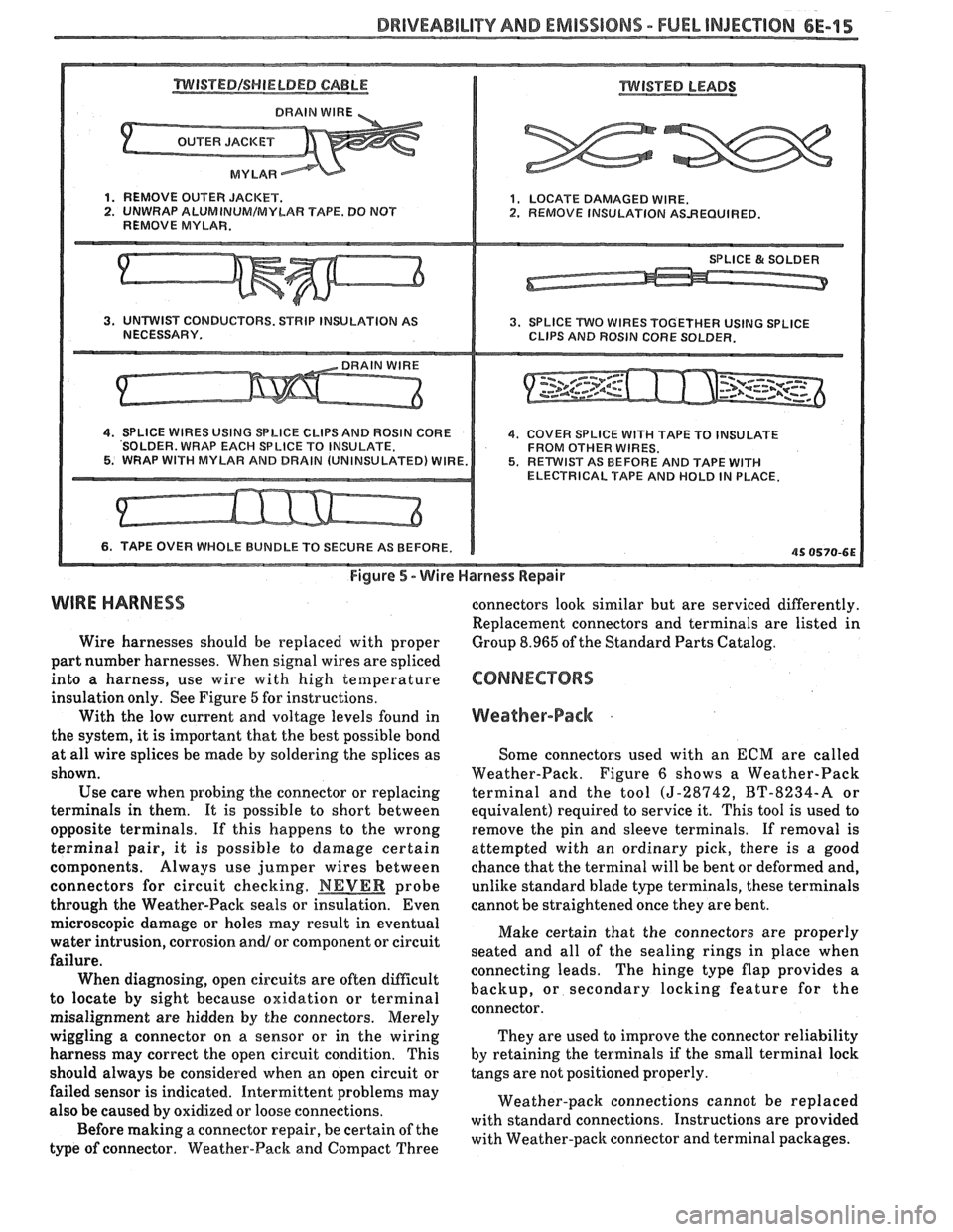
Figure 5 - Wire Harness Repair
WIRE HARNESS
Wire harnesses should be replaced with proper
part number harnesses. When signal wires are spliced
into a harness, use wire with high temperature
insulation only. See Figure
6 for instructions.
With the low current and voltage levels found in
the system, it
is important that the best possible bond
at all wire splices be
made by soldering the splices as
shown.
Use care when probing the connector or replacing
terminals in them. It is possible to short between
opposite terminals. If this happens to the wrong
terminal pair, it is possible
to damage certain
components. Always use jumper wires between
connectors for circuit checking.
NEVER probe
through the Weather-Pack seals or insulation. Even connectors
look similar but are serviced differently.
Replacement connectors and terminals are listed in
Group 8.965 of the Standard Parts Catalog.
Weather-Pack .
Some connectors used with an ECM are called
Weather-Pack. Figure
6 shows a Weather-Pack
terminal and the tool
(5-28942, BT-8234-A or
equivalent) required to service it. This tool is used to
remove the pin and sleeve terminals. If removal is
attempted with an ordinary pick, there is a good
chance that the terminal will be bent or deformed and,
unlike standard blade type terminals, these terminals
cannot be straightened once they are bent.
microscopic damage or holes may result in eventual
Make certain that the connectors are properly
water intrusion,
corr~sion an& or component or circuit
seated and all of the sealing rings in place when
failure. connecting leads. The hinge type flap provides a
When diagnosing, open circuits are often
difficult backup, or secondary locking feature for the
to locate by sight because oxidation or terminal
connector.
misalignment are hidden by the connectors. Merely
wiggling a connector on a sensor or in the wiring They
are used to improve the connector reliability
harness may correct the open circuit condition. This by
retaining the terminals
if the small terminal lock
should always be considered when an open circuit or tangs are not
positioned properly.
failed sensor is indicated. Intermittent problems may
Weather-pack connections cannot be replaced
also be caused by oxidized or loose connections.
with standard connections. Instructions are provided
Before making a connector repair, be certain of the
with Weather-pack connector and terminal packages.
type
of connector. Weather-Pack and Compact Three
Page 1067 of 1825
700-R4-16 AUTOMATIC TRANSMISSION
707
10 CASE, TRANSMISSION
707 SHAFT, MANUAL
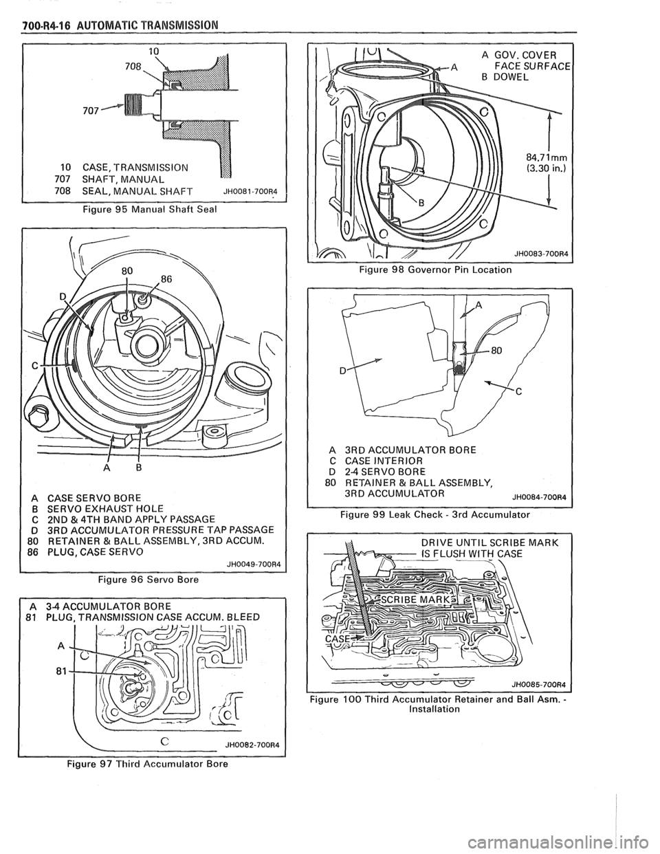
Figure
95 Manual Shaft Seal
~igu-r; 98 Governor Pin Location 1
A CASE SERVO BORE B SERVO EXHAUST HOLE
C 2ND
& 4TH BAND APPLY PASSAGE
D 3RD ACCUMULATOR PRESSURE TAP PASSAGE
80 RETAINER & BALL. ASSEMBLY, 3RD ACCUM.
86 PLUG, CASE SERVO
JH0049-700R4
Figure 96 Servo Bore
81 PLUG. TRANSMISSION CASE ACCUM. BLEED A
3RDACCUMULATOR BORE
C CASE INTERIOR
D
2-4 SERVO BORE
80 RETAINER & BALL ASSEMBLY,
3RD ACCUMULATOR
JH0084-700R4
Figure 99 Leak Check - 3rd Accumulator
Figure
100 Third Accumulator Retainer and Ball Asm. - Installation
~i~ure97Ttiird Aecumularor Bore
Page 1126 of 1825
AUTOMATIC TRANSMISSION ON-VEHICLE SERVICE 7A1-7
7. Place
gear selector into "DRIVE". Oil Pressure
should be equal or not more than 10 psi
(34 kPa)
higher than in "PARK".
8. Increase engine speed to 1400 RPM. If oil
pressure does not increase, adjust
T.V. cable.
Refer to T.V. Cable Adjustment.
Remove or Disconnect (Figs. 5 thru 7)
1. Air cleaner.
2. T.V. cable terminal from throttle lever.
3. Cable housing from bracket while compressing
locking tangs.
4. Routing clips or straps.
5. Raise
car, see Section OA.
6. Bolt securing T.V. cable to transmission.
o Pull up on cable cover at transmission until
cable is visible.
7. Cable from transmission link.
8. Cable seal.
Install or Connect
1. New seal into transmission case hole.
2. Transmission end of cable to T.V. link and secure
to transmission case with bolt and washer
assembly. Torque to 10
Nam (7 Ib. ft.).
3. Cable routing clips or straps.
4. Lower car.
5. Pass cable through engine bracket and engage
locking tangs of cable on bracket.
6. Avoid damaging or kinking wire cable.
7. Cable terminal to throttle lever.
Inspect
o Pull on upper end of cable. It should travel
a short distance with light resistance caused
by the small return spring on the
T.V. lever.
When releasing the upper end of the T.V.
cable, it should return to the zero T.V.
position.
Adjust
o T.V. cable. Refer to Figs. 5 thru 7.
CHANGING FLUID AND FILTER
Remove or Disconnect
1. Raise the car and support properly, see Section
OA.
2. Place drain pan under transmission oil pan.
3. Oil pan bolts from the front and sides only.
4. Loosen rear oil pan bolts approximately 4 turns.
NOTICE: Do not damage the transmission case
or oil pan sealing surfaces.
5. Lightly tap oil pan with rubber mallet or pry to
allow fluid to drain.
- Inspect fluid color
- Refer to chart in Section 7A
6. Remaining oil pan bolts, oil pan and gasket. 7. Oil filter
and o-ring
- O-ring may be stuck in the case
e Transmission case and oil pan gasket
surfaces with solvent and air dry.
- All traces of old gasket material must
be removed
Install or Connect
o Coat o-ring seal with a small amount of
petrolatum
o New o-ring onto filter
e New filter into case
a Oil pan and new gasket
e Oil pan bolts 20 N.m (15 lbs. ft.)
8. Lower car.
9. Fill transmission to proper level with
DEXRONO I1 fluid or equivalent, see Section
7A.
10. Check "Cold"
fluid level reading for initial till.
Do not overfill.
11. Follow
the "Transmission Fluid Level Checking
Procedure" in Section 7A of this Service Manual.
12. Check
oil pan gasket for leaks.
700-R4 SERVICEABLE COMPONENTS
The following parts can be serviced with the
transmission in the vehicle:
o Throttle valve control cable and/or sleeve heal
Fill tube and/or seal
o Governor assembly
a Speedometer drive and/or driven gear
e Servo assembly
a Valve body assembly, spacer plate, gaskets,
throttle lever and bracket assembly, auxiliary
valve body, TCC solenoid, switch and
wir-iug.
a Converter to flexplate bolts.
a Oil pan and/or gasket, strainer assembly and "0"
ring.
e Pressure Regular Valve.
o Rear Oil Seal.
SERVO ASSEMBLY
Remove or Disconnect (Fig. 8)
Tool Required:
J 29714-A
1. Raise car and suitably support, see Section OA.
2. Torque Arm,
see Section
3D.
3. Propeller Shaft, see Section 4A.
4. Exhaust hanger.
5. Support transmission.
6. Crossmember and transmission moulll.
7. Two
transmission oil pan bolts below servo cover.
8. Install J 29714-A on oil pan and reinstall oil pan
bolts.
9. Depress servo cover
and remove retaining ring.
10. J 29714-A.