1988 PONTIAC FIERO ECU
[x] Cancel search: ECUPage 284 of 1825
REAR AXLE 48-1 1
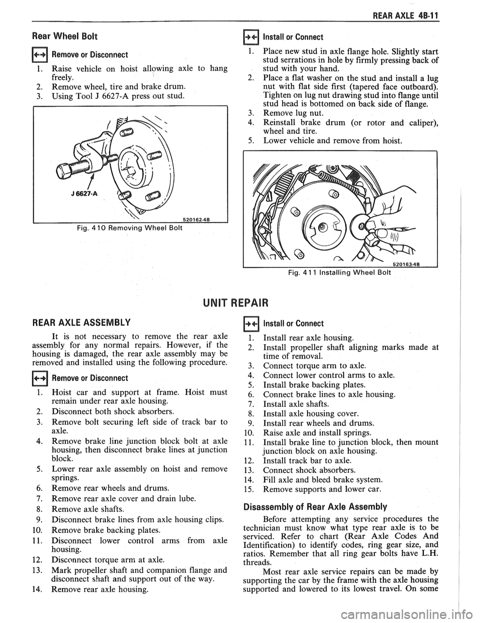
Rear Wheel Bolt
Remove or Disconnect 1.
1. Raise vehicle on hoist allowing axle to hang
freely. 2.
2. Remove
wheel, tire and brake drum.
3. Using Tool J 6627-A press out stud.
Fig. 4 10 Removing Wheel Bolt
REAR AXLE ASSEMBLY
Install or Connect
Fig. 4 11 Installing Wheel Bolt
UNIT REPAIR
Remove or Disconnect
Place new stud in axle flange hole. Slightly start
stud serrations in hole by firmly pressing back of
stud with your hand.
Place a flat washer on the stud and install a lug
nut with flat side first (tapered face outboard).
Tighten on lug nut drawing stud into flange until
stud head is bottomed on back side of flange.
Remove lug nut.
Reinstall brake drum (or rotor and caliper),
wheel and tire.
Lower vehicle and remove from hoist.
It is not necessary to remove the rear axle
assembly for any normal repairs. However, if the
housing is damaged, the rear axle assembly may be
removed and installed using the following procedure.
Hoist car and support at frame. Hoist must
remain under rear axle housing.
Disconnect both shock absorbers.
Remove bolt securing left side of track bar to
axle.
Remove brake line junction block bolt at axle
housing, then disconnect brake lines at junction
block.
Lower rear axle assembly on hoist and remove
springs.
Remove rear wheels and drums.
Remove rear axle cover and drain lube.
Remove axle shafts.
Disconnect brake lines from axle housing clips.
Remove brake backing plates.
Disconnect lower control arms from axle
housing.
Disconnect torque arm at axle.
Mark propeller shaft and companion flange and
disconnect shaft and support out of the way.
Remove rear axle housing.
Install or Connect
Install rear axle housing.
Install propeller shaft aligning marks made at
time of removal.
Connect torque arm to axle.
Connect lower control arms to axle.
Install brake backing plates.
Connect brake lines to axle housing.
Install axle shafts.
Install axle housing cover.
Install rear wheels and drums.
Raise axle and install springs.
Install brake line to junction block, then mount
junction block on axle housing.
Install track bar to axle.
Connect shock absorbers.
Fill axle and bleed brake system.
Remove supports and lower car.
Disassembly of Rear Axle Assembly
Before attempting any service procedures the
technician must know what type rear axle is to be
serviced. Refer to chart (Rear Axle Codes And
Identification) to identify codes, ring gear size, and
ratios. Remember that all ring gear bolts have L.H.
threads.
Most rear axle service repairs can be made by
supporting the car by the frame with the axle housing
supported and lowered to its lowest travel. On some
Page 318 of 1825

DISC BRAKE CALIPER ASSEMBLY 581-3
a Measure
Clearance between caliper (13) and bracket
(1 8) stops.
If necessary, remove caliper and file ends of
bracket
(18) stops to provide proper
clearance.
5. Inlet fitting (15), if removed, to 45 N-m (33 lb-ft).
6. Wheels and tires, aligning previous marks.
Remove wheel nuts securing rotor to hub.
e Lower car.
e Torque wheel nuts. See Section 3E
WHEELS AND TIRES.
7. Fill master cylinder to proper level with clean
brake fluid.
Bleed caliper if inlet fitting was removed.
Recheck fluid level.
CLEARANCE BEWEEN CALIPER AND
BRACKET STOPS
SHALL BE
0.13-0.30 MM (0.0050.012 IN.) THREE PLACES
13. CALIPER HOUSING
18. BRACKET
Figure 581-5 Caliper to Bracket Clearance
6. INBOARD SHOE B( LlNlNG 7. WEAR SENSOR 8. SHOE RETAINER
SPRING
13. CALIPER HOUSING
6
2. SLEEVE 3. BUSHING 4. BUSHING 5. OUTBOARD SHOE
LlNlNG
* LUBRICATE WITH SILICONE
Figure 58 1-6 Shoe & Lining Assembly
SHOE AND LINING ASSEMBLIES
Remove or Disconnect (Figures 5B1-6 through
581-18)
1. Calipe; as previously described.
2. Outboard shoe and lining
(5).
6, INBOARD SHOE 8. SHOE RETAINER
Figure 581-7 lnboard Shoe & Retainer
6. INBOARD SHOE B( 8. SHOE RETAINER
LINING SPRING
7. WEAR SENSOR 13. CALIPER HOUSING
Figure 581-8 Installing lnboard Shoe and Lining
5. OUTBOARD SHOE & LINING
13. CALIPER HOUSING
Figure 581-9 Installing Outboard Shoe & Lining
Install or Connect (Figures 581.6 through 581.10)
1. Lubricated new bushings (3 and 4) in grooves in
mounting bolt holes.
3. Inboard shoe and lining (6). 2. Lubricated sleeves (2) in mounting bolts holes.
4. Bushings (3 and 4) from grooves in mounting bolt
holes.
3. Retainer spring (8) on inboard shoe (6).
Page 324 of 1825
DISC BRAKE CALIPER ASSEMBLY 588-3
BO LT
FITTING
MOUNTING
31. BRAKE PIPE
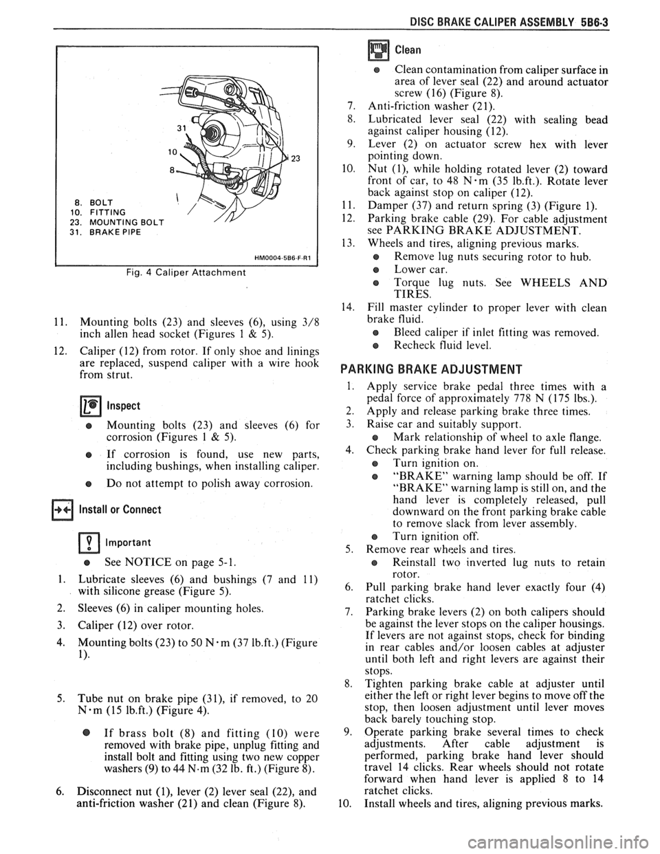
Fig. 4 Caliper Attachment
11. Mounting bolts (23) and sleeves (6), using 3/8
inch
allen head socket (Figures 1 & 5).
12. Caliper (12) from rotor. If only shoe and linings
are replaced, suspend caliper with a wire hook
from strut.
Inspect
e Mounting bolts (23) and sleeves (6) for
corrosion (Figures
1 & 5).
e If corrosion is found, use new parts,
including bushings, when installing caliper.
e Do not attempt to polish away corrosion.
Install or Connect
Important
See NOTICE on page 5- 1.
1. Lubricate sleeves (6) and bushings (7 and 11)
with silicone grease (Figure 5).
2. Sleeves
(6) in caliper mounting holes.
3. Caliper (12) over rotor.
4. Mounting bolts (23) to 50 N-m (37 1b.ft.) (Figure
1).
5.
Tube nut on brake pipe (31), if removed, to 20
N-m (15 1b.ft.) (Figure 4).
@ If brass bolt (8) and fitting (10) were
removed with brake pipe, unplug fitting and
install bolt and fitting using two new copper
washers
(9) to 44 N.m (32 lb. ft.) (Figure 8).
6. Disconnect nut (I), lever (2) lever seal (22), and
anti-friction washer (21) and clean (Figure 8).
Clean
Clean contamination from caliper surface in
area of lever seal (22) and around actuator
screw (16) (Figure 8).
7. Anti-friction washer (21).
8. Lubricated lever seal (22) with sealing bead
against caliper housing (12).
9. Lever (2) on actuator screw hex with lever
pointing down.
10. Nut
(I), while holding rotated lever (2) toward
front of car, to 48
N-m (35 1b.ft.). Rotate lever
back against stop on caliper (12).
11. Damper (37) and return spring (3) (Figure 1).
12. Parking brake cable (29). For cable adjustment
see PARKING BRAKE ADJUSTMENT.
13. Wheels and tires, aligning previous marks.
s Remove lug nuts securing rotor to hub.
e Lower car.
e Torque lug nuts. See WHEELS AND
TIRES.
14. Fill master cylinder to proper lever with clean
brake fluid.
e Bleed caliper if inlet fitting was removed.
Recheck fluid level.
PARKING BRAKE ADJUSTMENT
Apply service brake pedal three times with a
pedal force of approximately 778 N (175 lbs.).
Apply and release parking brake three times.
Raise car and suitably support.
e Mark relationship of wheel to axle flange.
Check parking brake hand lever for full release.
e Turn ignition on.
e "BRAKE" warning lamp should be off. If
"BRAKE" warning lamp is still on, and the
hand lever is completely released, pull
downward on the front parking brake cable
to remove slack from lever assembly.
Turn ignition off.
Remove rear wheels and tires.
e Reinstall two inverted lug nuts to retain
rotor.
Pull parking brake hand lever exactly four (4)
ratchet clicks.
Parking brake levers (2) on both calipers should
be against the lever stops on the caliper housings.
If levers are not against stops, check for binding
in rear cables and/or loosen cables at adjuster
until both left and right levers are against their
stops.
Tighten parking brake cable at adjuster until
either the left or right lever begins to move off the
stop, then loosen adjustment until lever moves
back barely touching stop.
Operate parking brake several times to check
adjustments. After cable adjustment is
performed, parking brake hand lever should
travel 14 clicks. Rear wheels should not rotate
forward when hand lever is applied
8 to 14
ratchet clicks.
Install wheels and tires, aligning previous marks.
Page 325 of 1825

e Remove lug nuts securing rotor to hub.
e Lower car.
o Torque lug nuts. See WHEELS AND
TIRES.
SHOE AND LINING ASSEMBLIES
Figures 5 thru 8
Remove or Disconnect
1. Caliper as previously described.
2 Outboard shoe and lining (27) (Figure 5).
Install or Connect
1. Lubricated new bushings (7 and 11) (Figure 5).
2. Lubricated new two-way check valve (19) into
end of piston (18) (Figure 8).
3. Inboard shoe and lining (25). Slide edge of metal
shoe under ends of dampening spring (28) and
snap shoe into position against piston. Back of
shoe must lay flat against piston (Figure 6).
Fig. 6 Installing Inboard Shoe and Lining
26. WEAR SENSOR 25. INBOARD SHOE & 27. OUTBOARD SHOE & LINING
ASE (OR EQUIVALENT)
Fig. 5 Shoe & Linings Assemblies
3. Inboard shoe and lining (25) (Figure 6).
4. Bushings (7 and 11) from grooves in mounting
bolt holes (Figure 5).
5. Two-way check valve (19) from end of piston (18)
using small screwdriver (Figure 8). D-shaped
tab (33) on shoe must engage
D-shaped notch (32) in piston. If tab and
hole do not line up, turn piston with spanner
wrench
J 7624 or equivalent (Figure 6).
r, Wear sensor (26) should be at leading edge
of shoe during forward wheel rotation
(Figure 5).
4. Outboard
shoe and lining (27). Back of shoe must
lay flat against caliper (Figure
5).
5. Caliper as previously described.
6. Apply approximately 778
N (175 lb.) force three
times to brake pedal to seat linings.
7. Position
12-inch channel lock pliers over brake
shoe ears and bottom edge of caliper (12). While
holding moderate force
(50 lb.) on brake pedal,
clinch outboard shoe (27) (Figure 7).
NOTICE: If leakage is noted form piston hole
after check valve is removed, overhaul caliper as
specified.
Page 367 of 1825
6A2-16 2.8 LITER V-6
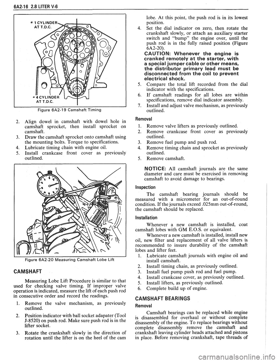
Figure 6A2-19 Camshaft Timing
2. Align dowel in camshaft with dowel hole in
camshaft sprocket, then install sprocket on
camshaft.
3. Draw the camshaft sprocket onto camshaft using
the mounting bolts. Torque to specifications.
4. Lubricate timing chain with engine oil.
5. Install crankcase front cover as previously
outlined.
Figure 6A2-20 Measuring Camshaft Lobe Lift
CAMSHAFT
Measuring Lobe Lift Procedure is similar to that
used for checking valve timing. If improper valve
operation is indicated, measure the lift of each push rod
in consecutive order and record the readings.
1. Remove the valve mechanism, as previously
outlined.
2. Position
indicator with ball socket adapater (Tool
5-8520) on push rod. Make sure push rod is in the
lifter socket.
3. Rotate the crankshaft slowly in the direction of
rotation until the lifter is on the heel of the cam lobe.
At this point, the push rod is in its lowest
position.
4. Set the dial indicator on zero, then rotate the
crankshaft slowly, or attach an auxiliary starter
switch and "bump" the engine over, until the
push rod is in the fully raised position (Figure
6A2-20).
CAUTION: Whenever the engine is
cranked remotely at the starter, with
a special jumper cable or other means,
the distributor primary lead must be
disconnected from the coil to prevent
electrical shock.
5. Compare the total lift recorded from the dial
indicator with the specifications.
6. If camshaft readings for all lobes are within
specifications, remove dial indicator assembly.
7. Install and adjust valve mechanism, as previously
outlined.
Removal
1. Remove valve lifters as previously outlined.
2. Remove crankcase front cover as previously
outlined.
3. Remove fuel pump and push rod.
4. Remove timing chain and sprocket as previously
outlined.
5. Remove camshaft.
NOTICE: All camshaft journals are the same
diameter and care must be exercised in removing
camshaft to avoid damage to bearings.
Inspection
The camshaft bearing journals should be
measured with a micrometer for an out-of-round
condition. If the journals exceed
.025mm out-of-round,
the camshaft should be replaced.
Installation
Whenever a new camshaft is installed, coat
camshaft lobes with
GM E.O.S, or equivalent.
Whenever a new camshaft is installed, install new
oil, new filter and replacement of all valve lifters is
recommended to insure durability of the camshaft
lobes and lifter feet.
1. Lubricate camshaft journals with engine oil and
install camshaft.
2. Install timing chain, as previously outlined.
3. Install fuel pump push rod and fuel pump.
4. Install crankcase cover, as previously outlined.
5. Install
lifters, as previously outlined.
6. Complete build up of engine.
CAMSHAFT BEARINGS
Removal
Camshaft bearings can be replaced while engine
is disassembled for overhaul or without complete
disassembly of the engine. To replace bearings without
complete disassembly remove the camshaft and
crankshaft leaving cylinder heads attached and pistons
in place. Before removing crankshaft, tape threads of
Page 376 of 1825
2.8 LITER V-6 6A2-25
Fitting
1. Select rings comparable in size to the piston being
used.
2. Slip
the compression ring in the cylinder bore;
then press the ring down into the cylinder bore
about 6mm above ring travel. Be sure ring is
square with cylinder wall.
3. Measure the space or gap between the ends of the
ring with a feeler gage (Figure
6A2-33).
4. If
the gap between the ends of the ring is below
specifications, remove the ring and try another
for fit.
5. Fit each compression ring to the cylinder in
which it is going to be used.
6. If the pistons have not been cleaned and inspected
as previously outlined, do so.
7. Slip the outer surface of the top and second
compression ring into the respective piston ring
groove and roll the ring entirely around the
groove (Figure
6A2-34). If binding occurs at any
point, the cause should be determined. If there is
a ring groove, remove by dressing with a fine cut
file. If the binding is caused by a distorted ring,
check a new ring.
Installation
1. Install oil ring spacer in groove being sure ends
are butted and not overlapped.
2. Hold
spacer ends butted and install lower steel oil
ring rail.
3. Install upper
steel oil ring rail with gap staggered.
4. Flex
the oil ring assembly to make sure ring is
free. If binding occurs, the cause should be
detemined. If caused by ring groove, remove by
dressing groove with a fine cut file. If binding is
caused by a distorted ring, check a new ring.
5. Install second compression ring. Stagger gap
from other rings.
6. Install top compression ring with gap properly
located.
ENGINE ASSEMBLY
Removal
Disconnect battery.
Remove air cleaner.
Remove hood. Drain radiator.
Remove lower radiator hose.
Remove upper fan shroud.
Remove upper radiator hose and coolant
recovery hose.
Remove transmission cooler lines. Remove radiator.
Remove fan assembly.
Remove heater hoses.
Disconnect carburetor linkage, includes cruise
control detent cable.
Remove vacuum brake booster line.
Remove distributor cap and lay wiring aside.
Disconnect necessary wires and hoses.
Remove power steering pump and lay aside. Raise
vehicle.
Remove exhaust pipes at exhaust manifold.
Remove dust cover.
Remove converter bolts.
Disconnect starter wires.
Remove bell housing bolts.
Remove motor mount through bolts.
Disconnect fuel lines at fuel pump.
Lower vehicle. Support transmission.
Remove
A.I.R./Converter pipes bracket.
Remove engine, include removing wire from
bracket at rear left of engine.
Installation
Position engine assembly in vehicle.
Attach motor mount to engine brackets and
lower engine in place.
Remove engine lifting device.
Remove transmission floor jack.
Raise vehicle on hoist.
Install mount "through" bolts. Torque to
specifications.
Install bell housing bolts. Torque to
specifications.
On vehicles with automatic transmission, install
converter to flywheel attaching bolts. Torque to
specifications.
Install flywheel splash shield of conveter housing
cover as applicable. Torque attaching bolts to
specifications.
Install starter wires.
Connect fuel lines.
Connect exhaust pipe at manifold.
Lower vehicle on hoist.
Reinstall power steering pump, if so equipped.
Connect necessary wires and hoses.
Install radiator and fan shroud and reconnect
radiator and heater hoses.
Fill cooling system.
Fill crankcase with oil. See owner's manual for
specifications.
Install air cleaner.
Install hood.
Connect battery cables.
NOTICE: To avoid possible arcing of battery,
connect positive battery cable first.
22. Start engine, check for leaks and check timing.
CRANKSHAFT
The crankshaft can be removed while the engine
is dissasembled for overhaul, as previously outlined or
without complete disassembly.
Removal
1. With the engine removed from the vehicle,
remove the clutch assembly (if equipped) and
flywheel. Mount engine in stand and clamp
securely.
Page 407 of 1825
6A3-28 V-8 ENGINE
16. Install
radiator and fan shroud and reconnect
radiator and heater hoses.
17. Fill cooling system.
18. Fill
crankcase with oil. See owner's manual for
specifications.
19. Install air cleaner.
20. Install hood.
21. Connect battery cables.
NOTICE: To avoid possible arcing of battery,
connect positive battery cable first.
22. Start engine, check for leaks and check timing.
CRANKSHAFT
The crankshaft can be removed while the engine
is disassembled for overhaul, as previously outlined, or
without complete disassembly.
Removal
With the engine removed from the vehicle and the
transmission and/or clutch housing removed
from the engine, mount engine in stand and
clamp securely.
Remove the oil dip stick and oil dip stick tube, (if
applicable).
Remove the starting motor, clutch assembly (if
equipped) and flywheel.
Remove the spark plugs.
Remove crankshaft pulley and torsional damper.
Remove oil pan and oil pump.
Remove crankcase front cover, and if so
equipped, remove timing chain and camshaft
sprocket.
Check the connecting rod caps for cylinder
number identification. If necessary, mark them.
Remove the connecting rod caps and push the
pistons to top of bores.
Remove main bearing caps and lift crankshaft out
of cylinder block.
Remove rear main bearing oil seal and main
bearings from cylinder block and main bearing
caps.
Cleaning and Inspection
1. Wash crankshaft in solvent and dry with
compressed air.
2. Measure dimensions of main bearing journals and
crankpins with a micrometer for out-of-round,
taper or undersize. (See Specifications.) 3.
Check crankshaft for run-out by supporting at
the front and rear main bearings journals in
"V"
blocks and check at the front and rear
intermediate journals with a dial indicator. (See
Specifications.)
4. Replace or recondition the crankshaft if out of
specifications.
SPROCKET OR GEAR REPLACEMENT
e Remove crankshaft sprocket using Tool
5-5825, install using Tool J-5590.
Installation
1.
Install rear main bearing oil seal in cylinder block
and rear main bearing cap grooves. Install with
lip of seal toward front of engine. Where seal has
two lips install lip with helix towards front of
engine.
2. Lubricate lips of seal with engine oil. Keep oil off
parting line surface.
3. Install main bearings in cylinder block and main
bearing caps then lubricate bearing surface with
engine oil.
4. Install crankshaft, being careful not to damage
bearing surfaces.
5. Recheck bearing clearances using plastigage.
6. Apply a thin coat of brush-on type oil sealing
compound to block mating surface and
corresponding surface of cap only. Do not allow
sealant on crankshaft or seal.
7. Install main bearing caps with arrows pointing
toward front of engine.
8. Torque all except rear main bearing cap bolts to
specifications. Torque rear main bearing cap bolts
to 10-12 lbs. ft. (14-16
N.m)then tap end of
crankshaft, first rearward then forward with a
lead hammer. This will line up rear main bearing
and crankshaft thrust surfaces.
Retorque all main
bearing cap bolts to specifications.
9. Measure crankshaft end play with a feeler gage.
Force crankshaft forward and measure clearance
between the front of the rear main bearing and the
crankshaft thrust surface.
10. Install flywheel and torque to specifications. A
wood block placed between the crankshaft and
cylinder block will prevent crankshaft from
rotating.
Align dowel hole in flywheel with dowel
hole in crankshaft. On vehicles equipped
with automatic transmissions, install
flywheel with the converter attaching pads
towards transmission.
GENERAL DATA
TYPE .................................................................................................................................. 90" V-8
DISPLACEMENT
............................................................................... 305 Cu. In., 350 Cu. In.
......................................................... LITER (VIN) ................................... ...... 5.0, (E), (F), 5.7 (8)
RPO ......................................................................................................................... L03, LB9, L98
BORE ........................................................................................................................ 3.736, 4.000
STROKE
........................... .. ....................................................................................... 3.480, 3.480
COMPRESSION RATIO
................................................................................... 931, 931, 9.5:1
FIRING ORDER .................................................................................................... 1-8-4-3-6-5-7-2
Page 413 of 1825
BB-2 ENGINE COOLING
strength, which protects the radiator by relieving
pressure if it exceeds design limits. The vacuum valve
is held against its seat by a light spring, which permits
opening of the valve to relieve vacuum created in the
system when it cools off and which otherwise might
cause the radiator to collapse.
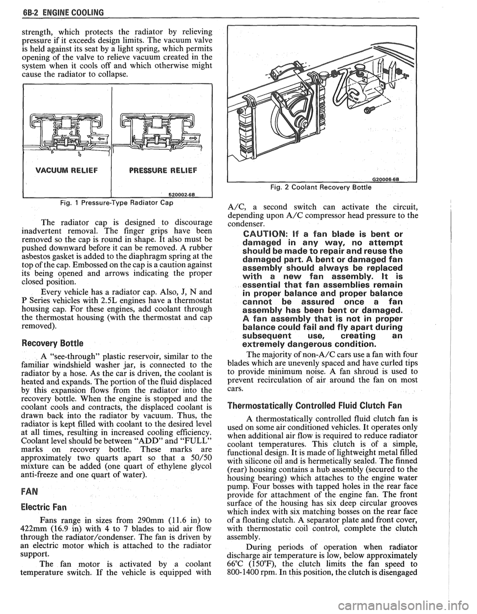
VACUUM RELIEF PRESSURE RELIEF
Fig. 1 Pressure-Type Radiator Cap
The radiator cap is designed to discourage
inadvertent removal. The finger grips have been
removed so the cap is round in shape. It also must be
pushed downward before it can be removed. A rubber
asbestos gasket is added to the diaphragm spring at the
top of the cap. Embossed on the cap is a caution against
its being opened and arrows indicating the proper
closed position.
Every vehicle has a radiator cap. Also,
J, N and
P Series vehicles with 2.5L engines have a thermostat
housing cap. For these engines, add coolant through
the thermostat housing (with the thermostat and cap
removed).
Recovery Bottle
A "see-through" plastic reservoir, similar to the
familiar windshield washer jar, is connected to the
radiator by a hose. As the car is driven, the coolant is
heated and expands. The portion of the fluid displaced
by this expansion flows from the radiator into the
recovery bottle. When the engine is stopped and the
coolant cools and contracts, the displaced coolant is
drawn back into the radiator by vacuum. Thus, the
radiator is kept filled with coolant to the desired level
at all times, resulting in increased cooling efficiency.
Coolant level should be between "ADD" and
"FULL"
marks on recovery bottle. These marks are
approximately two quarts apart so that a
50/50
mixture can be added (one quart of ethylene glycol
anti-freeze and one quart of water).
FAN
Electric Fan
Fans range in sizes from 290mm (11.6 in) to
422mm (16.9 in) with 4 to 7 blades to aid air flow
through the
radiator/condenser. The fan is driven by
an electric motor which is attached to the radiator
support.
The fan motor is activated by a coolant
temperature switch. If the vehicle is equipped with
Fig. 2 Coolant Recovery Bottle
A/C, a second switch can activate the circuit,
depending upon
A/C compressor head pressure to the
condenser.
CAUTION: If a fan blade is bent or
damaged in any way, no attempt
should be made to repair and reuse the
damaged part.
A bent or damaged fan
assembly should always be replaced
with a new fan assembly. It is
essential that fan assemblies remain
in proper balance and proper balance
cannot be assured once a fan
assembly has been bent or damaged.
A fan assembly that is not in proper
balance could fail and fly apart during
subsequent use, creating an
extremely dangerous condition.
The majority of non-A/C cars use a fan with four
blades which are unevenly spaced and have curled tips
to provide minimum noise.
A fan shroud is used to
prevent recirculation of air around the fan on most
cars.
Thermostatically Controlled Fluid Clutch Fan
A thermostatically controlled fluid clutch fan is
used on some air conditioned vehicles. It operates only
when additional air flow is required to reduce radiator
coolant temperatures. This clutch is of a simple,
functional design. It is made of lightweight metal filled
with silicone oil and is hermetically sealed. The finned
(rear) housing contains a hub assembly (secured to the
housing bearing) which attaches to the engine water
pump. Four bosses with tapped holes in the rear face
provide for attachment of the engine fan. The front
surface of the housing has six deep circular grooves
which index with six matching bosses on the rear face
of a floating clutch. A separator plate and front cover,
with thermostatic coil control, complete the clutch
assembly.
During periods of operation when radiator
discharge air temperature is low, below approximately
66°C (150°F), the clutch limits the fan speed to
800- 1400 rpm. In this position, the clutch is disengaged