1988 PONTIAC FIERO display
[x] Cancel search: displayPage 829 of 1825
6E3-A-26 5.OL (VIM F) & 5.7L (VIN 8) DRIVEABILITY AND EMISSIONS
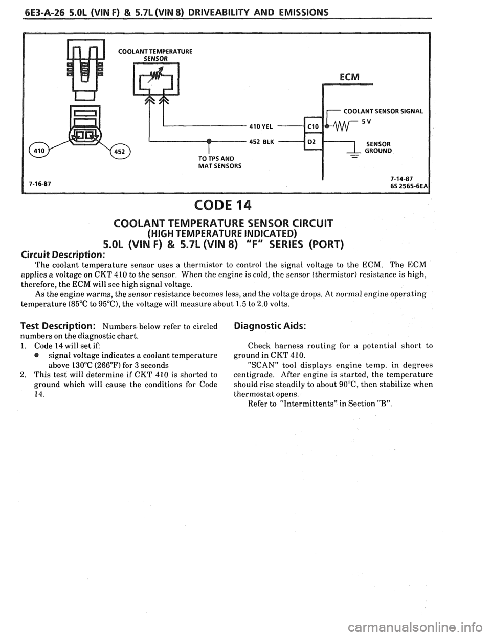
COOLANT SENSOR SIGNAL
-
CODE 14
COOLANT TEMPERATURE SENSOR CIRCUIT
(HIGH TEMPERATURE INDICATED)
5.OL (VIN F) & 5.7L (VIN 8) "F"" SERIES (PORT)
Circuit Description:
The coolant temperature sensor uses a thermistor to control the signal voltage to the ECM. The ECM
applies a voltage on CKT 410 to the sensor. When the engine is cold, the sensor (thermistor) resistance is high,
therefore, the ECM will see high signal voltage.
As the engine warms, the sensor resistance becomes less, and the voltage drops.
At normal engine operating
temperature
(85°C to 95"C), the voltage will measure about 1.5 to 2.0 volts.
Test Description: Numbers below refer to circled
numbers on the diagnostic chart.
1. Code 14 will set if:
@ signal voltage indicates a coolant temperature
above 130°C (266°F) for
3 seconds
2. This test will determine if CKT 410 is shorted to
ground which will cause the conditions for Code
14.
Diagnostic Aids:
Check harness routing for a potential short to
ground in
CKT 410.
"SCAN" tool displays engine temp, in degrees
centigrade. After engine is started, the temperature
should rise steadily to about
90°C, then stabilize when
thermostat opens.
Refer to "Intermittents" in Section
"B".
Page 836 of 1825
DRIVEABILITY AND EMISSIONS 5.OL (VIN F) & 5.7L (VIN 8) 6E3-A-33
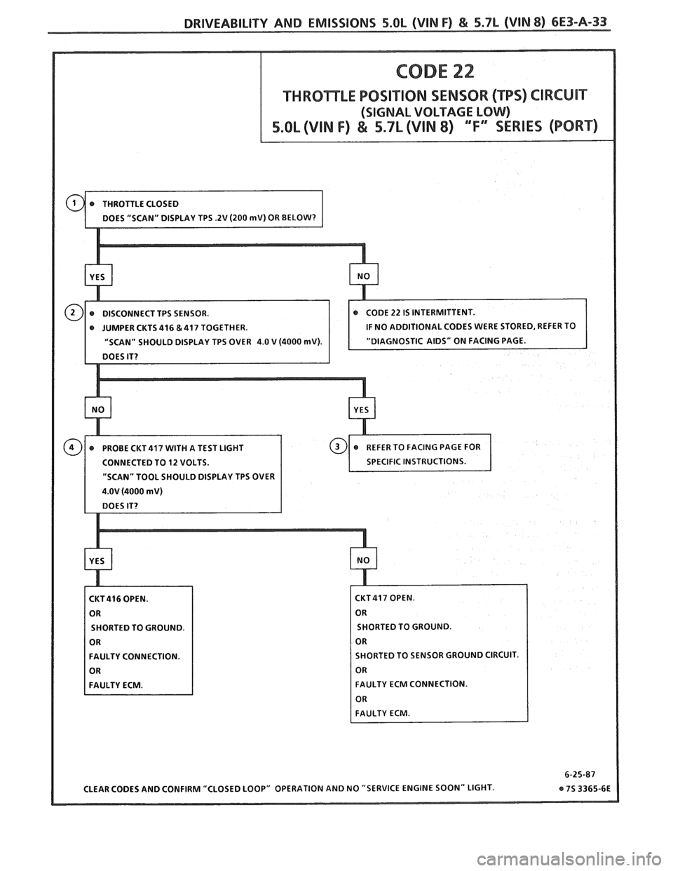
(SIGNAL VOLTAGE LOW)
JUMPER CKTS 416 & 417 TOGETHER.
"SCAN" SHOULD DISPLAY TPS OVER
4.0 V (4000 mV
"SCAN" TOOL SHOULD DISPLAY TPS OVER
SHORTED TO GROUND
FAULTY CONNECTION. ORTED
TO SENSOR GROUND CIRCUIT.
FAULTY ECM CONNECTION.
Page 839 of 1825
6E3-A-36 5.OL (VIN F) & 5.7L (VIN 8) DRIVEABILITY AND EMISSIONS
CONNECTOR
15- WAY .I.P. CONNECTOR - - PARK OR NEUTRAL
CODE 24
VEHICLE SPEED SENSOR (VSS) CIRCUIT
5.0L (VIN F) & S.SL (VIN 8) "F" SERIES (PORT)
rcuit Description:
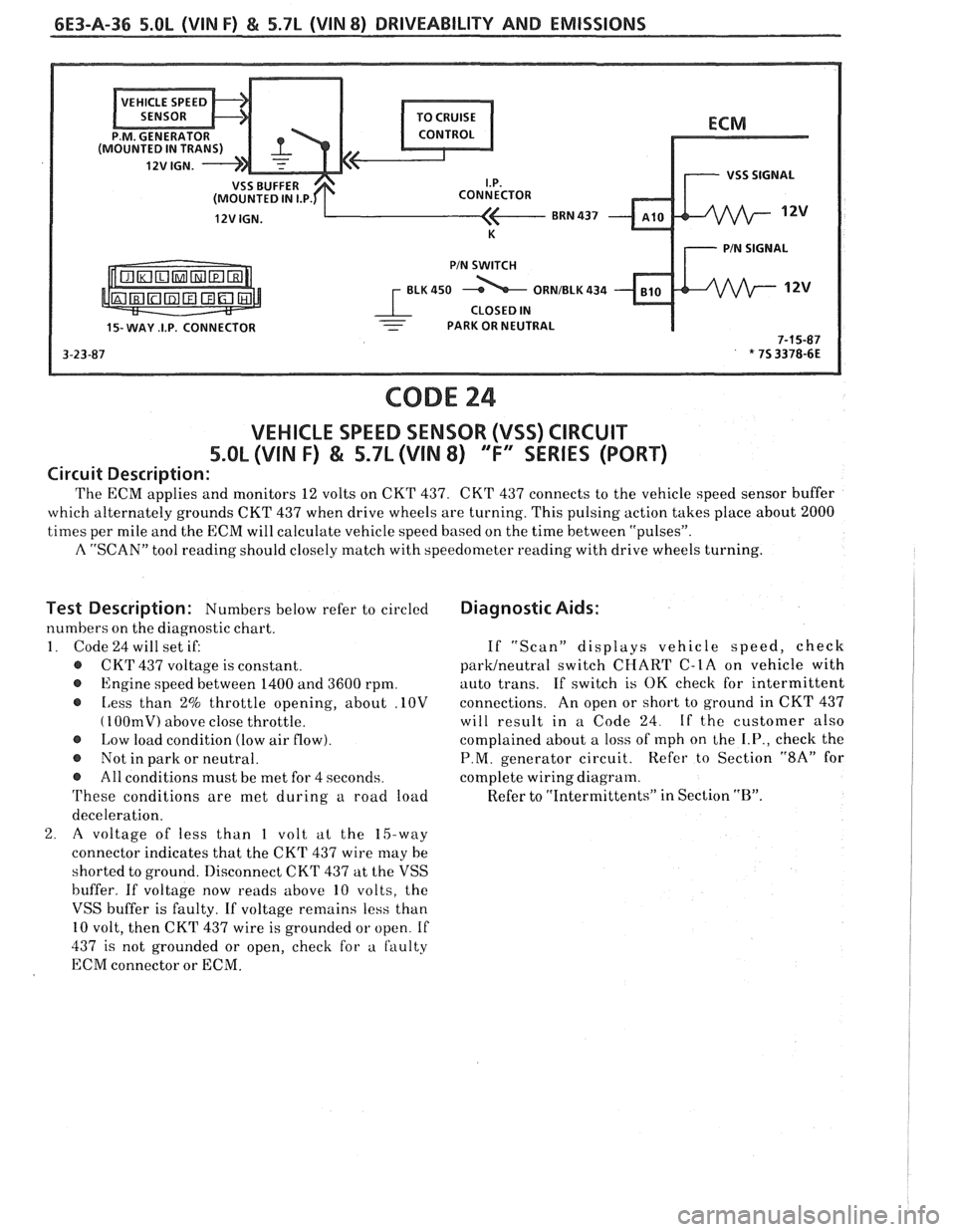
'I'he ECM applies and monitors 12 volts on CKT 437. CK'I' 437 connects to the vehicle speed sensor buffer
which alternately grounds CKT 437 when drive wheels are turning. This pulsing action takes place about 2000
times per mile and the ECM will calculate vehicle speed based on the time between "pulses".
A "SCAN" tool reading should closely match with speedometer reading with drive wheels turning.
Test Description: Numbers below refer to circled
numbers on the diagnostic chart.
1. Code
24 will set it
@ CKT 437 voltage is constant.
@ Engine speed between 1400 and 3600 rpm.
@ Less than 2% throttle opening, about .10V
( 100mV) above close throttle.
@ Low load condition (low air flow).
@ Not in park or neutral.
@ All conditions must be met for 4 seconds.
'I'hese conditions are met during a road load
deceleration.
2. A voltage of less than 1 volt at the 15-way
connector indicates that the CKT 437 wire may be
shorted to ground. Disconnect CKT 437 at the VSS
buffer. If voltage now reads above 10 volts, the
VSS buffer is faulty. If voltage remains less than
10 volt, then CKT 437 wire is grounded
or open. If
437 is not grounded or open, check for a faulty
ECM connector or ECM.
Diagnostic Aids:
If "Scan" displays vehicle speed, check
parWneutra1 switch CHART C-1A on vehicle with
auto trans. If switch is
OK check for intermittent
connections. An open or short to ground in CKT 437
will result in a Code 24
If the customer also
complained about a loss of mph on the
I.P., check the
P.M. generator circuit. Refer to Section "8A" for
complete wiring diagram.
Refer to "Intermittents" in Section
"B".
Page 840 of 1825
DRIVEABILITY AND EMISSIONS 5.OL (WIN F) & 5.7L (WIN 8) 6E3-A-37
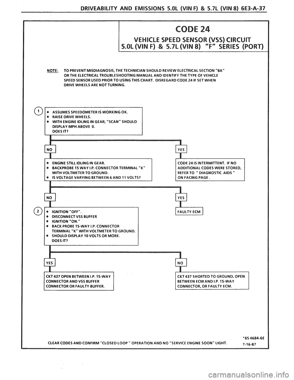
OR THE ELECTRICAL TROUBLESHOOTING MANUAL AND IDENTIFY THE TYPE OF VEHICLE
SPEED SENSOR USED PRIOR TO USING
THIS CHART. DISREGARD CODE 24 IF SET WHEN
DRIVE WHEELS ARE NOT TURNING.
MPH ABOVE
0.
REFER TO " DIAGNOSTIC AIDS "
0 DISCONNECT VSS BUFFER 0 IGNITION "ON." 0 BACK PROBE 15-WAY I.P. CONNECTOR
SHOULD DISPLAY
10 VOLTS OR MORE.
Page 842 of 1825
DRIVEABILITY AND EMISSIONS 5.OL (VIN F) & 5.7L (VIN 8) 6E3-A-39
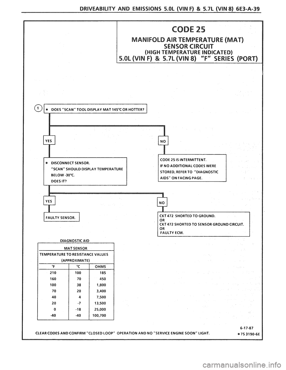
MANIFOLD AIR TEMPERATURE (MAT)
IF NO ADDITIONAL CODES WERE
"SCAN" SHOULD DISPLAY TEMPERATURE
BELOW
-30°C.
DIAGNOSTIC AID
MAT SENSOR
TEMPERATURE TO RESISTANCE VALUES
(APPROXIMATE)
CLEAR CODES AND CONFIRM "CLOSED LOOP" OPERATION AND NO "SERVICE ENGINE SOON" LIGHT.
Page 855 of 1825
6E3-A-52 5.OL (VIN F) & 5.7L (VIN 8) DRIVEABILITY AND EMISSIONS
CODE 43
ELECTRONIC SPARK CONTROL (ESC) ClRCUlT
5.OL (VIN F) & 5.7L (VIN 8) 'TF" SERIES (PORT)
Circuit Description:
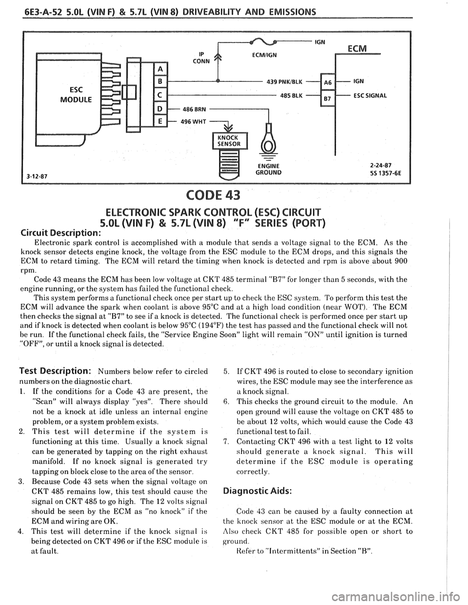
Electronic spark control is accomplished with a module that sends a voltage signal to the ECM. As the
knock sensor detects engine knock, the voltage from the ESC module to the ECM drops, and this signals the
ECM to retard timing. The ECM will retard the timing when knock is detected and rpm is above about 900
rpm.
Code 43 means the ECM has been low voltage at CKT 485 terminal
"R7" for longer than 5 seconds, with the
engine running, or the system has failed the functional check.
This system performs a functional check once per start up to check the
ESC system. To perform this test the
ECM will advance the spark when coolant is above 95°C and at a high load condition (near
WOT). The ECM
then checks the signal at
"B7" to see if a knock is detected. The functional check is performed once per start up
and if knock is detected when coolant is below 95°C
(194°F') the test has passed and the functional check will not
be run. If the functional check fails, the "Service Engine Soon" light will remain
"ON" until ignition is turned
"OFF", or until a knock signal is detected.
Test Description: Numbers below refer to circled
numbers on the diagnostic chart.
1. If the conditions for a Code 43 are present, the
"Scan" will always display "yes". There should
not be a knock at idle unless an internal engine
problem, or
a system problem exists.
2. This test will determine if the system is
functioning at this time. Usually
a knock signal
can be generated by tapping on the right exhaust
manifold. If no knock signal is generated try
tapping on block close to the area of the sensor.
3. Because Code 43 sets when the signal voltage on
CKT 485 remains low, this test should cause the
signal on CKT 485 to go high. The
12 volts signal
should be seen by the ECM as "no knock" if the
ECM and wiring are OK.
4. This test will determine if the knock signal
is
being detected on CKT 496 or if the ESC module is
at fault. 5.
If CKT
496 is routed to close to secondary ignition
wires, the ESC module may see the interference as
a knock signal.
6. This checks the ground circuit to the module. An
open ground will cause the voltage on CKT 485 to
be about
12 volts, which would cause the Code 43
functional test to fail.
7. Contacting CKT 496 with a test light to 12 volts
should generate a knock signal. This will
determine if the ESC module is operating
correctly.
Diagnostic Aids:
Code 33 can be caused by a faulty connection at
the knock sensor at the ESC module or at the ECM.
Also check CKT 485 for possible open or short to
ground.
Refer to "Intermittents" in Section "R".
Page 857 of 1825
6E3-A-54 5.OL (VIN F) & 5.7L (VIN 8) DRIVEABILITY AND EMISSIONS
OXYGEN ( O2 ) SENSOR
CODE 44
OXYGEN SENSOR CIRCUIT
(LEAN EXHAUST INDICATED)
5.OL (VIN F) & 5.7L (VIN 8) '"F" "SERIES (PORT)
Circuit Description:
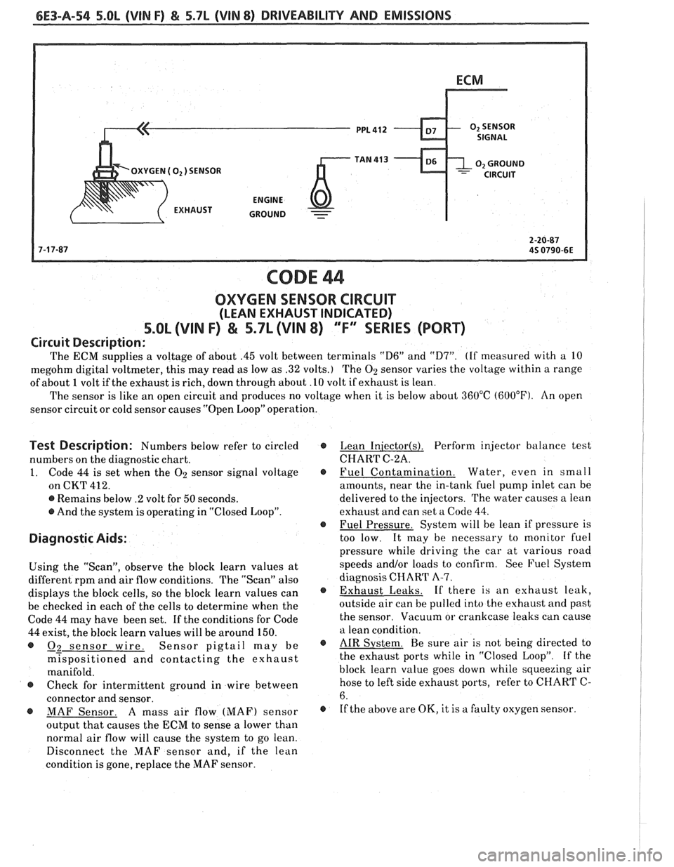
The ECM supplies a voltage of about .45 volt between terminals "D6" and "D7". (If measured with a 10
megohm digital voltmeter, this may read as low as .32 volts.) The
02 sensor varies the voltage within a range
of about 1 volt if the exhaust is rich, down through about .10 volt if exhaust is lean.
The sensor is like an open circuit and produces no voltage when it is below about 360°C
(600°F). An open
sensor circuit or cold sensor causes "Open Loop" operation.
Test Description: Numbers below refer to circled @
numbers on the diagnostic chart.
1. Code 44 is set when the O2 sensor signal voltage @
on CKT 412.
@ Remains below .2 volt for 50 seconds.
@ And the system is operating in "Closed Loop".
@
Diagnostic Aids:
Using the "Scan", observe the block learn values at
different rpm and air flow conditions. The "Scan" also
displays the block cells, so the block learn values can
@
be checked in each of the cells to determine when the
Code 44 may have been set.
If the conditions for Code
44 exist, the block learn values will be around 150.
@ - 02 sensor wire. Sensor pigtail may be @
m~spositioned and contacting the exhaust
manifold.
@ Check for intermittent ground in wire between
connector and sensor.
@ MAF Sensor. A mass air flow (MAF) sensor @
output that causes the ECM to sense a lower than
normal air flow will cause the system to go lean.
Disconnect the
MAF sensor and, if the lean
condition is gone, replace the
MAF sensor. Lean
Iniector(s). Perform
injector balance test
CHART C-2A.
Fuel Contamination. Water,
even in small
amounts, near the in-tank fuel pump inlet can be
delivered to the injectors. The water causes a lean
exhaust and can set a Code 44.
Fuel Pressure. System will be lean if pressure is
too low.
It may be necessary to monitor fuel
pressure while driving the car at various road
speeds
and/or loads to confirm. See Fuel System
diagnosis CHART
A-7.
Exhaust Leaks. If there is an exhaust leak,
outside air can be pulled into the exhaust and past
the sensor. Vacuum or crankcase leaks can cause
a lean condition.
AIR System. Be sure air is not being directed to
the exhaust ports while in "Closed Loop". If the
block learn value goes down while squeezing air
hose to left side exhaust ports, refer to CHART
C-
6.
If the above are
OK, it is a faulty oxygen sensor.
Page 859 of 1825
6E3-A-56 5.OL (VIN F) & 5.7L (VIN 8) DRIVEABILITY AND EMISSIONS
OXYGEN ( O2 )SENSOR
-
CODE 45
OXYGEN SENSOR CIRCUIT
(RICH EXHAUST INDICATED)
S.OL (VIN F) & 5.7L (VIN 8) ""F-ERIES (PORT)
Circuit Description:
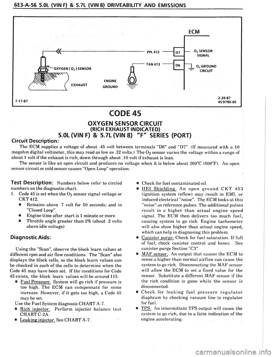
The ECM supplies a voltage of about .45 volt between terminals "D6" and "D7". (If measured with a 10
megohm digital voltmeter, this may read as low as .32 volts.) The
02 sensor varies the voltage within a range of
about 1 volt if the exhaust is rich, down through about .10 volt if exhaust is lean.
The sensor is like an open circuit and produces no voltage when it is below about 360°C (600°F). An open
sensor circuit or cold sensor causes "Open Loop" operation.
Test Description: Numbers below refer to circled @ Check for fuel contaminated oil.
numbers on the diagnostic chart.
@ HE1 Shielding. An open ground CKT 453
1. Code 45 is set when the
02 sensor signal voltage or
(ignition system reflow) may result in EMI, or
CKT 412.
induced electrical "noise". The ECM looks at this
@ Remains above .7 volt for 50 seconds; and in
"noise" as reference pulses. The additional pulses
"Closed Loop".
result in a higher than actual engine speed
@ Engine time after start is 1 minute or more.
signal. The ECM then delivers too much fuel,
@ Throttle angle greater than 2% (about .2 volts
causing system to go rich. Engine tachometer
above idle voltage) will also show higher than actual engine speed,
which can help in diagnosing this problem.
Diagnostic Aids: @ Canister purge. Check for fuel saturation. If full
of fuel, check canister control and hoses. See
Using the "Scan", observe the block learn values at canister
purge Section
"C3".
different rpm and air flow conditions. The "Scan" also @ MAF sensor. An output that causes the ECM to
displays the block cells, so the block learn values can sense
a higher than normal airflow can cause the
be checked in each of the cells to determine when the system
to go rich. Disconnecting the MAF sensor
Code 45 may have been set. If the conditions for Code will
allow the ECM to set a fixed value for the
45 exists, the block learn values will be around 115. sensor.
Substitute a different MAF sensor if the
@ Fuel Pressure. System will go rich if pressure is the
rich condition is gone while the sensor is
too high. The ECM can compensate for some disconnected.
increase. However, if it gets too high, a Code 45
@ Check for leaking fuel pressure regulator
may be set. diaphram
by checking vacuum line to regulator
Use the Fuel System diagnosis CHART A-7. for
fuel.
@ Rich
iniector. Perform injector balance test @ TPS. An intermittent TPS output will cause the
CHART C-2A.
system to go rich, due to a false indication of the
@ Leaking injector. See CHART A-7. engine
accelerating.