1988 PONTIAC FIERO display
[x] Cancel search: displayPage 1167 of 1825
Page
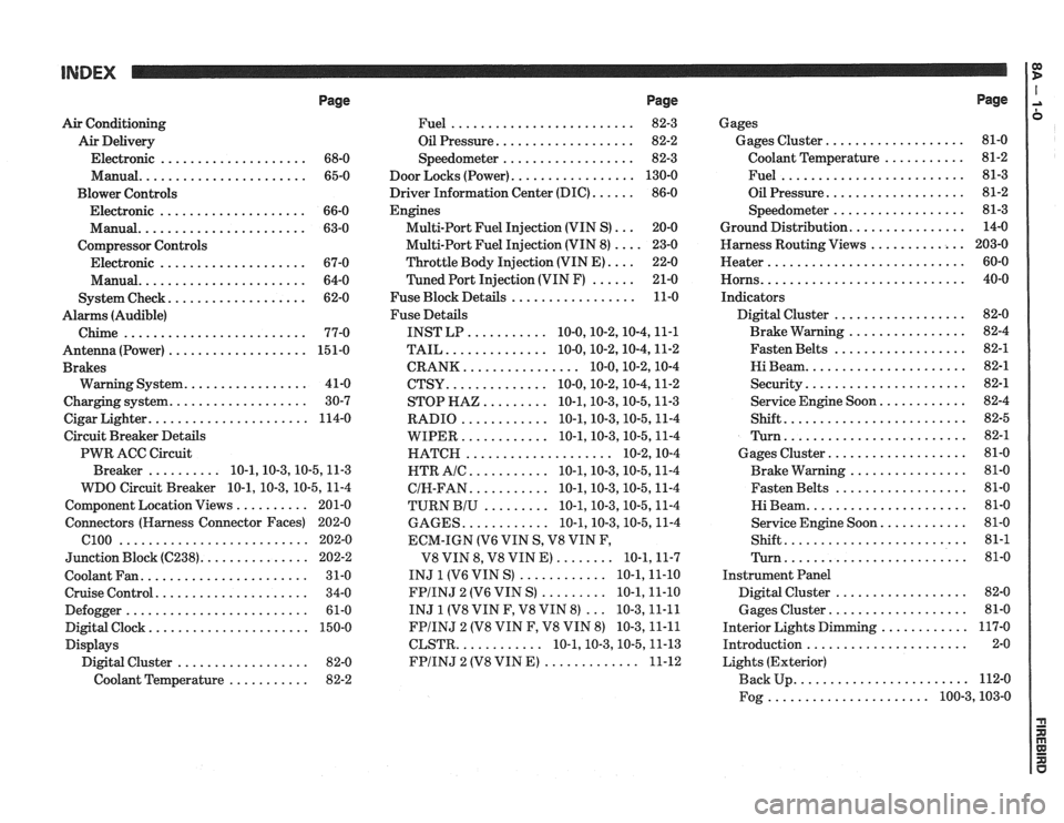
Air Conditioning
Air Delivery
Electronic
.................... 68-0
Manual
....................... 65-0
Blower Controls
Electronic
.................... 66-0
Manual
....................... 63-0
Compressor Controls Electronic
.................... 67-0
Manual
....................... 64-0
................... System Check 62-0
Alarms (Audible)
Chime
......................... 77-0
Antenna(Power) ................... 151-0
Brakes
................. Warning System 41-0
................... Charging system 30-7
...................... Cigar Lighter 114-0
Circuit Breaker Details
PWR ACC Circuit
.......... Breaker 10.1.10.3.10.5.1 1.3
WDO Circuit Breaker
10.1. 10.3. 10.5. 11-4
.......... Component Location Views 201-0
Connectors (Harness Connector Faces) 202-0
el00 .......................... 202-0
............... Junction Block ((2238) 202-2
Coolant Fan
....................... 31-0
Cruise Control
..................... 34-0
Defogger
......................... 61-0
Digital Clock
...................... 150-0
Displays Digital Cluster
.................. 82-0
Coolant Temperature
........... 82-2
Page
......................... Fuel 82-3
................... Oil Pressure 82-2
.................. Speedometer 82-3
................. Door Locks (Power) 130-0
...... Driver Information Center (DIC) 86-0
Engines
... Multi-Port Fuel Injection (VIN S) 20-0
.... Multi-Port Fuel Injection (VIN 8) 23-0
.... Throttle
Body Injection (VIN E) 22-0
...... Tuned
Port Injection (VIN F) 21-0
................. Fuse Block Details 11-0
Fuse Details
........... INST LP 10.0.10.2.10.4.1 1.1
.............. TAIL 10.0.10.2.10.4.1 1.2
................ CRANK 10.0.10.2.1 0.4
.............. CTSY 10~0.10.2.10.4.1 1.2
......... STOP HAZ 10.1.10.3.10.5.1 1.3
............ RADIO 10.1.10.3.10.5.1 1.4
............ WIPER 10.1.10.3.10.5.1 1.4
.................... HATCH 10.2.1 0.4
........... HTR AlC 10.1.10.3.10.5.1 1.4
........... CIH.FAN 10.1.10.3.10.5.1 1.4
......... TURN BIU 10.1.10.3.10.5.1 1.4
............ GAGES 10.1.10.3.10.5.1 1.4
ECM-IGN
(V6 VIN S. V8 VIN F.
........ V8 VIN 8. V8 VIN E) 10.1.1 1.7
............ INJ 1 (V6 VIN S) 10.1.1 1.10
......... FPIINJ 2 (V6 VIN S) 10.1.1 1.10
... INJ 1 (V8 VIN F. V8 VIN 8) 10.3.1 1.11
FPIINJ 2 (V8 VIN F. V8 VIN 8) 10.3.1 1.11
............ CLSTR 10.1.10.3.10.5.1 1.13
............. FPIINJ 2 (V8 VIN E) 11-12
Page
Gages
................... Gages Cluster 81-0
........... Coolant Temperature 81-2
......................... Fuel 81-3
................... Oil Pressure 81-2
.................. Speedometer 81-3
................ Ground Distribution 14-0
Harness Routing Views
............. 203-0
........................... Heater 60-0
............................ Horns 40-0
Indicators
.................. Digital Cluster 82-0
................ Brake Warning 82-4
.................. Fasten Belts 82-1
...................... Hi Beam 82-1
...................... Security 82-1
............ Service Engine Soon 82-4
......................... Shift 82-5
......................... Turn 82-1
................... Gages Cluster 81-0
................ Brake Warning 81-0
.................. Fasten Belts 81-0
...................... Hi Beam 81-0
............ Service Engine Soon 81-0
......................... Shift 81-1
......................... Turn 81-0
Instrument Panel
Digital Cluster
.................. 82-0
Gages Cluster
................... 81-0
............ Interior Lights Dimming 117-0
...................... Introduction 2-0
Lights (Exterior)
........................ Back Up 112-0
...................... Fog 100.3,10 3.0
Page 1179 of 1825
SYMBOLS
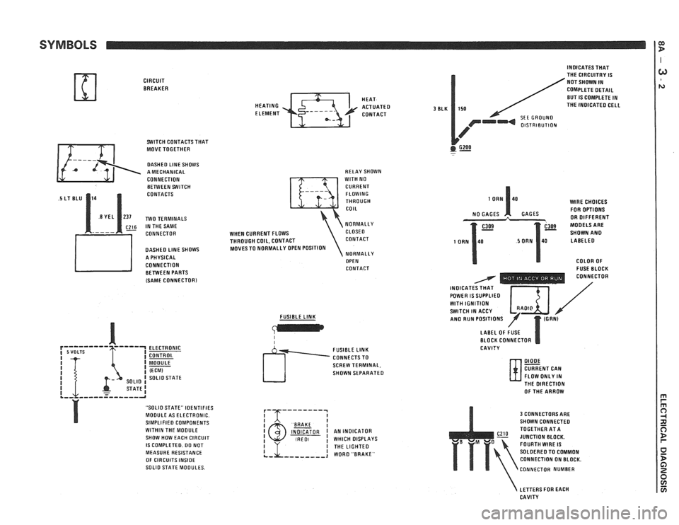
CIRCUIT BREAKER
SWITCH CONTACTS THAT
MOVE TOGETHER
DASHED LlNE SHOWS
A MECHANICAL
CONNECTION BETWEEN SWITCH
CONTACTS
~26 IN THE SAME
CONNECTOR
DASHED
LlNE SHOWS
A PHYSICAL
CONNECTION BETWEEN PARTS
(SAME
CONNECTORl
ELECTRONIC
CONTROL
MODULE
(ECM) SOLlO STATE
STATE1 .,, ,,,--=----,-a
"SOLIO STATE" IDENTIFIES
MODULE AS ELECTRONIC.
SIMPLIFIED COMPONENTS
WITHIN THE MOOULE
SHOW HOW EACH CIRCUIT
IS COMPLETED. DO NOT
MEASURE RESISTANCE
OF CIRCUITS
INSIDE SOLlO STATE MODULES. HEAT
HEATING
ACTUATED ELEMENT CONTACT
RELAY SHOWN
WlTH NO
CURRENT FLOWING
THROUGH
COIL
NORMALLY
WHEN CURRENT FLOWS CLOSE0
THROUGH COIL, CONTACT CONTACT
MOVES TO NORMALLY OPEN POSITION
NORMALLY
OPEN
CONTACT
FUSIBLE
LINK
I I
SCREW TERMINAL,
SHOWN SEPARATED
I BAAKE I INDICATOR I AN INDICATOR (RED, ! WHICH DISPLAYS
3 BLK
INDICATES THAT
THE CIRCUITRY IS
NOT SHOWN IN
COMPLETE DETAIL
BUT
IS COMPLETE IN
150 THE INOICATED CELL
SEE GROUND OlSTRlBUTlON
GZOO . -
WlRE CHOICES
FOR OPTIONS
GAGES OR DIFFERENT
SHOWN
AN0 LABELED
COLOR OF
- FUSE BLOCK - - - - - - - . . CONNECTOR
INOICAT / POWER IS SUPPLIED I $ I / WlTH IGNITION SWITCH IN ACCY /' AN0 RUN POSITIONS
LABEL OF FUSE
BLOCK CONNECTOR
CAVITY
DIODE CURRENT CAN
FLOW ONLY IN
N- THE DIRECTION
OF THE ARROW
3 CONNECTORS ARE
SHOWN CONNECTED
TOGETHER AT A
JUNCTION BLOCK.
FOURTH
WIRE IS
SOLDERED TO COMMON
CONNECTION ON BLOCK.
CONNECTOR NUMBER
LETTERS FOR EACH
CAVITY
Page 1221 of 1825
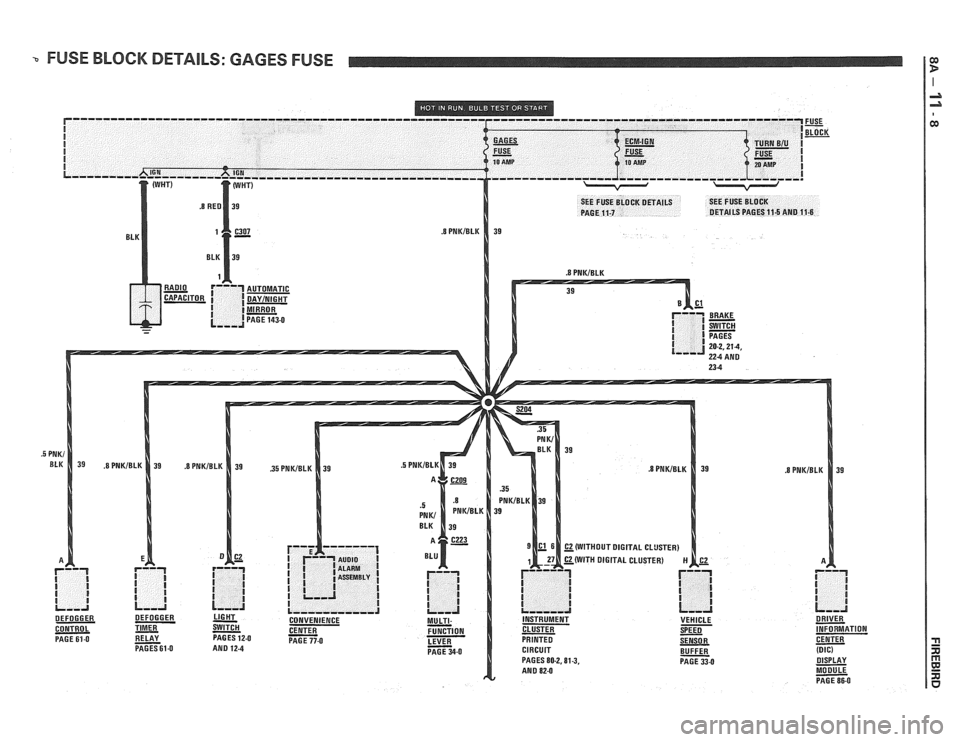
-. FUSE BLOCK DETAILS: GAGES FUSE
(WITH DIGITAL CLUSTER)
CONTROL
- PAGE 61.0 - RELAY PAGESGI-0 BUFFER - (DIG) PAGES 80-2.81.3, PAGE 33-0 - DISPLAY
MODULE
- PAGE 86-0
Page 1324 of 1825
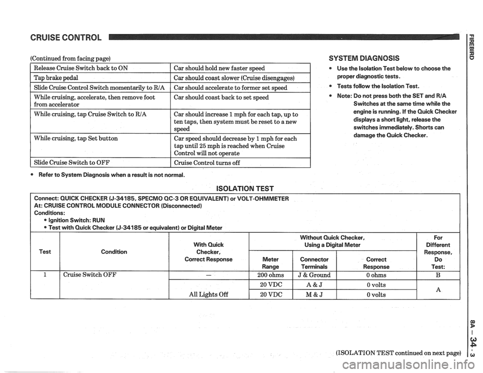
CRUISE CONTROL 2
I Slide Cruise Control Switch momentaril~ to RIA I Car should accelerate to former set s~eed I
(Continued from facing page)
--
While cruising, accelerate, then remove foot I car should coast back to set speed
from accelerator
Release Cruise Switch
back to ON
Tap brake pedal
I While cruising, tap Cruise Switch to RIA I Car should increase 1 mph for each tap, up to I
Car should hold new faster speed
Car should coast slower (Cruise disengages)
tap
until 25 mph is reached when cruise
Control will not o~erate I
While cruising, tap Set button
1 Slide Cruise Switch to OFF ten
taps, then system must be reset to a new
speed
Car speed should decrease by
1 mph for each
I Cruise Control turns off 1
0 Refer to System Diagnosis when a result is not normal.
SYSTEM DIAGNOSIS
@ Use the isolation Test below to choose the
proper diagnostic tests.
@ Tests follow the Isolation Test.
Note: Do not press both the SET and RIA
Switches at the same time while the
engine is running. If the Quick Checker
displays
a short light, release the
switches immediately. Shorts can
damage the Quick Checker.
lSOLATlON TEST
Connect: QUICK CHECKER (J-34185, SPECMO QC-3 OR EQUIVALENT) or VOLT-OHMMETER
At: CRUISE CONTROL MODULE CONNECTOR (Disconnected)
Conditions:
@ Ignition Switch: RUN
Test with Quick Checker
(J-34185 or equivalent) or Digital Meter
Test Condition
Cruise Switch OFF
(ISOLATION TEST continued on next page)
All Lights Off
With Quick
Checker,
Correct Response
-
20 VDC
20 VDC
For
Different
Response, Do
Test:
B
Without Quick Checker,
Using a Digital Meter
A&J
M&J
Meter
Range
200 ohms
0 volts
0 volts
Connector
Terminals
J & Ground
A
Correct
Response
0 ohms
Page 1411 of 1825
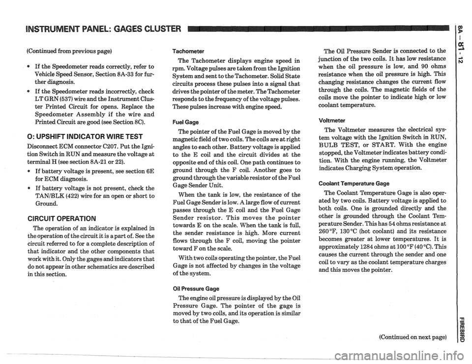
(Continued from previous page)
If the Speedometer reads correctly, refer to
Vehicle Speed Sensor, Section
8A-33 for fur-
ther diagnosis.
If the Speedometer reads incorrectly, check
LT GRN (537) wire and the Instrument Clus-
ter Printed Circuit for opens. Replace the
Speedometer Assembly if the wire and
Printed Circuit are good (see Section
8C).
O: UPSHIFT INDICATOR WIRE TEST
Disconnect ECM connector C207. Put the Igni-
tion Switch in RUN and measure the voltage at
terminal
H (see section 8A-21 or 22).
If battery voltage is present, see section
6E
for ECM diagnosis.
If battery voltage is not present, check the
TANIBLK (422) wire for an open or short to
Ground.
CIRCUIT OPERATION
The operation of an indicator is explained in
the operation of the circuit it is apart of. See the
circuit referred to for a complete description of
that indicator and the other components that
work with it. Only the gages and indicators that
do not appear in other schematics are described
in this section.
Tachometer
The Tachometer displays engine speed in
rpm. Voltage pulses are taken from the Ignition
System and sent to the Tachometer. Solid State
circuits process these pulses into a signal that
drives the pointer of the meter. The Tachometer
responds to the frequency of the voltage pulses.
These pulses increase with engine speed.
Fuel Gage
The pointer of the Fuel Gage is moved by the
magnetic field of two coils. The coils are at right
angles to each other. Battery voltage is applied
to the E coil and the circuit divides at the
opposite end of this coil. One path continues to
ground through the F coil. Another goes to
ground through the variable resistor of the Fuel
Gage Sender Unit.
When the tank is low, the resistance of the
Fuel Gage Sender is low. A large flow of current
passes through the E coil and the Fuel Gage
Sender resistor. This moves the pointer
towards E on the scale. When the tank is
full,
the sender resistance is high. More current
flows through the F coil, moving the pointer
toward F on the scale.
With two coils operating the pointer, the Fuel
Gage is not affected by changes in the voltage
of the system.
011 Pressure Gage
The engine oil pressure is displayed by the Oil
Pressure Gage. The pointer of the gage is
moved by two coils, and its operation is similar
to that of the Fuel Gage. The
Oil Pressure Sender is connected to the
junction of the two coils.
It has low resistance
when the oil pressure is low, and 90 ohms
resistance when the oil pressure is high. This
changing resistance changes the current flow
through the coils. The magnetic fields of the
coils move the pointer to indicate high or low
coolant temperature.
Voltmeter
The Voltmeter measures the electrical sys-
tem voltage with the Ignition Switch in RUN,
BULB TEST, or START. With the engine
stopped, the Voltmeter indicates battery condi-
tion. With the engine
running, the Voltmeter
indicates Charging System operation.
Coolant Temperature Gage
The Coolant Temperature Gage is also oper-
ated by two coils. Battery voltage is applied to
both coils. One is grounded directly
and the
other is grounded through the Coolant Tem-
perature Sender. This has 54 ohms resistance at
260
OF, 130 "C (hot coolant) and its resistance
becomes greater at lower temperatures. It is
appr~ximately 1284 ohms at 100 OF (40 '6). This
causes the current through the sender and one
coil to vary as the coolant temperature charges
and this moves the pointer.
Page 1421 of 1825
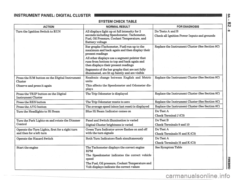
INSTRUMENT PANEL: DIGITAL CLUSTER 1 fE!
SYSTEM CHECK TABLE
FOR DIAGNOSIS
Do Tests A and B
Check
all Ignition Power Inputs and grounds
Replace the Instrument Cluster (See Section
8C)
ACTION
Turn the Ignition Switch to RUN
Observe and press it again
Replace the Instrument Cluster (See Section
8C)
The Speedometer indicates the correct vehicle
The Fuel, Oil pressure, Coolant Temperature and
Volt displays indicate the correct values I I I
NORMAL RESULT
All displays light up at full intensity for 2
seconds including Speedometer, Tachometer,
Fuel, Oil Pressure, Coolant Temperature, and
Battery voltage
Bar graphs (Tachometer, Fuel) run up to the
maximum and back again and then display their
present readings
All other displays use a segment pointer that
runs from bottom to top and back again and
then displays their present readings
Segments of the bar graphs that are not fully
illuminated, are
lit up faintly and are visible
Page 1422 of 1825
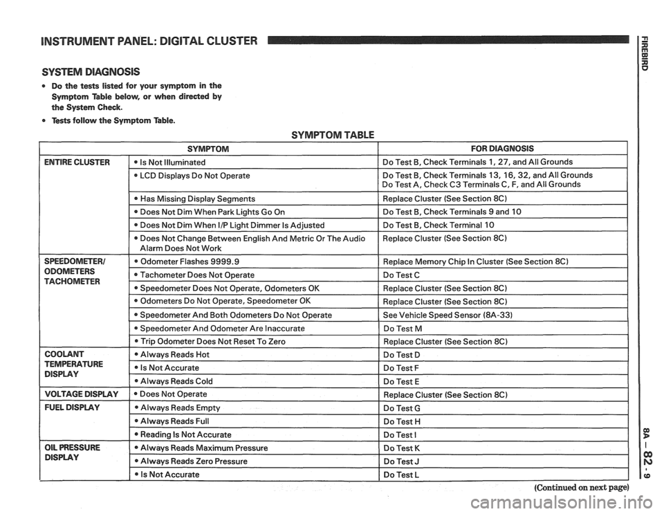
INSTRUMENT PANEL: DlGlTAL CLUSTER a
SYSTEM DIAGNOSIS
0 Do the tests listed for your symptom in the
Symptom Table below, or when
direded by
the System Check.
0 Tests follow the Symptom Table.
SYMPTOM TABLE
SYMPTOM FOR DIAGNOSIS
ENTIRE CLUSTER - -
0 Is Not Illuminated Do
Test B, Check Terminals 1, 27, and All Grounds
LCD Displays Do Not Operate Do
Test B, Check Terminals 13,
16,32, and All Grounds
Do Test A, Check C3 Terminals C, F, and All Grounds
I 0 Has Missing Display Senments I Replace Cluster (See Section 8C) I
Does Not Dim When Park Lights Go On Do
Test B, Check Terminals 9 and 10
Does Not Dim When
I/P Light Dimmer Is Adjusted Do
Test B, Check Terminal 10
0 Does Not Change Between English And Metric Or The Audio Replace
Cluster (See Section 8C)
Alarm Does Not Work
SPEEDOMETER1 Odometer Flashes 9999.9 Replace Memory Chip In Cluster (See Section 8Cl
ODOMETERS Tachometer Does Not Operate Do Test C TACHOMETER 0 Speedometer Does Not Operate, Odometers OK Replace Cluster (See Section 8C)
I 0 Trip Odometer Does ~otReset To Zero I Redace Cluster (See Section 8C) I
I COOLANT I 0 Always Reads Hot I Do Test D I
TEMPERATURE Is Not Accurate DISPLAY Do Test F
Always Reads Cold
Do Test E
I VOLTAGE DISPLAY I e Does Not Operate
FUEL DISPLAY Always Reads Empty
0 Always Reads Full
I 0 Reading Is Not Accurate - --
OIL PRESSURE Always Reads Maximum Pressure
DlSPLAV 0 Always Reads Zero Pressure
I 0 Is Not Accurate Replace
Cluster (See Section 8C)
Do Test
G
Do Test H I
Do Test I
Do Test K
Do Test J I
Do Test L I pp
(Continued on next page)
Page 1426 of 1825
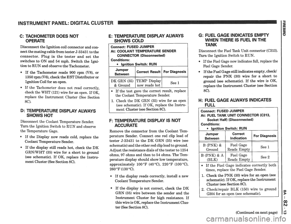
INSTRUMENT PANEL: DIGITAL CLUSTER
6: TAGHOMETER DOES NOT
OPEWTE
Disconnect the Ignition coil connector and con-
nect the matingcable from tester 5-33431 to the
connector. Plug in the tester and set the
switches to ON and 54 mph. Switch the Igni-
tion to RUN and observe the Tachometer.
If the Tachometer reads 900 rpm
(V8), or
1350
rpm (V6), check the EST Distributor or
Ignition Coil for an open.
If the Tachometer does not read correctly,
check the WHT (121) wire for an open. If OK,
replace the Instrument Cluster (See Section
8C).
D: TEMPEFIATURE DISPWY ALWAYS
SHOW nm
Disconnect the Coolant Temperature Sender.
Tum the Ignition Switch to RUN and observe
the Temperature Gage.
If the Display now reads cold, replace the
Coolant Temperature Sender.
* If the display still reads hot, check the DK
GRNIWHT (35) wire for a short to ground
(see schematic). If
OK, replace the Instru-
ment Cluster (See Section
86).
E: TEMPEFIATURE DISPLPIY ALMS
SHOWS GOLD
At: COOLANT TEMPERATURE SENDER
CONNECTOR (Disconnected)
Conditions:
Jumper
Between
F: TEMPEWTURE DISPWY IS NCIT
AGCUME
Remove the connector from the Coolant Tem-
perature Sender. Connect one red clip lead of
tester 5-33431 to the DK GRN (35) wire (see
schematic) and the other red clip lead to ground.
Adjust the resistance dials of the tester to 1254
ohms,
97 ohms and then to 54 ohms. The Tem-
perature display should show low temperature,
approximately 100
OF (40 "C), 220 OF (100 "C),
260 OF (130 "6).
r If the display reads correctly, install a new
Coolant Temperature Sender.
If the display is not correct, check the DK
GRN (35) wire between the sender and the
Instrument Cluster for high resistance. If
this wire is OK, replace the Instrument Clus-
ter (See Section
8C).
DK GRN (35)
& Ground
6: FUEL GAGE INDICATES EMPW
WHEN THERE IS FUEL IN THE
TANK
Correct Result
Disconnect the F'uel Tank Unit connector (C313).
Turn the Ignition Switch to RUN.
For Diagnosis
If the test gave the correct result, replace
the Coolant Temperature Sender.
1. Check the DK GRN (35) wire for an open
(see schematic). If OK, replace the Instru-
ment Cluster (see Section
8C).
TEMP Display
now reads hot
@ If the Fuel Gage now indicates full, replace the
F'uel Gage Sender.
See
a If the Fuel Gage still indicates empty, check/
repair the PNK (30) wire for a short to
ground (see schematic). If the wire is OK,
replace the Instrument Cluster (see Section
8C).
El: FUEL GAGE ALWAYS lNDl6ATES
FULL
Connect: FUSED JUMPER
At: FUEL TANK
UNIT CONNECTOR (C313,
Socket Half) (Disconnected)
Conditions: ignition Switch: RUN
I B (PNK) & I Fuel Gage I See (
Ground Reads Empty
Jumper
Between
If the Fuel Gage indicates correctly both
times, replace the Fuel Gage Sender.
1. Check the PNK (30) wire for an open (see
schematic).
If OK, replace the Instrument
Cluster (see Section
8C).
2. ChecMrepair BLK (150) wire to ground
6304 for an open (see schematic).
Correct
indication
B (PNK) & A
(BLK)
(Continued on next page)
For Diagnosis
Fuel Gage
Reads Empty See
2