1988 PONTIAC FIERO fuel filter
[x] Cancel search: fuel filterPage 712 of 1825
DRIVEABILITY AND EMISSIONS 2.8L (VIN S) 6E3-B-3
e A faulty in-tank fuel pump check valve will @ If engine starts but then immediately stalls,
allow the fuel in the lines to drain back to the open
distributor by-pass line. If engine then
tank after the engine is stopped. To check for starts
and runs OK, replace pickup coil.
this condition:
@ If engine starts and stalls, disconnect MAF
Perform Fuel System Diagnosis, CHART A-7. sensor. If engine then runs and sensor
@ Remove spark plugs. Check for wet plugs, connections are OK, replace the sensor.
cracks, wear, improper gap, burned
f lectrodes,
or heavy deposits. Repair or replace as
necessary.
HESITATION, SAG, STUMBLE
Definition: Momentary lack of response as the accelerator is pushed down. Can
occur at all car speeds.
Usually most severe when first trying to make the car move, as
from a stop sign. May cause the engine to stall if severe enough.
Perform careful visual check as described at
start of Section
"B".
a CHECK:
- Fuel pressure. See CHART A-7. Also check for
water contaminated fuel.
- Air leaks at air duct between MAF sensor and
throttle body.
- Spark plugs for being fouled or faulty wiring.
- PROM (2.8L) or MEM-CAL (5.OL & 5.7L)
number. Also check service bulletins for latest
MEM-CAL or PROM.
- TPS for binding or sticking. Voltage should
increase at a steady rate as throttle is moved
toward WOT.
- Ignition timing. See Emission Control
Information label.
- Generator output voltage. Repair if less than 9
or more than 16 volts.
- HE1 ground, CKT 453.
- Canister purge system for proper operation.
See CHART C-3.
- EGR - See CHART C-7.
@ Perform injector balance test CHART C-2A.
SURGES AND/OR CHUGGLE
Definition: Engine power variation under steady
throttle or cruise. Feels like the car speeds up and
slows down with no change in the accelerator pedal.
Be sure driver understands transmission
converter clutch and
A/C compressor operation
in Owner's Manual.
e Perform careful visual inspection as described
at start of Section
"B".
CHECK:
- TCC and 4th gear switch operation - See
CHART C-8A.
- Loose or leaking air duct between MAF sensor
and throttle body.
- Generator output voltage. Repair if less than 9
or more than 16 volts.
- EGR - There should be no EGR at idle. See
CHART C-7. Also check for plugged EGR
solenoid filter.
- Vacuum lines for kinks or leaks.
- Ignition timing. See Emission Control
Information label.
- In-line fuel filter. Replace ifdirty or plugged.
- Fuel pressure while condition exists. See
CHART A-7.
@ Inspect oxygen sensor for silicone contamination
from fuel, or use of improper RTV sealant. The
sensor may have a white, powdery coating and
result in a high but false signal voltage (rich
exhaust indication). The ECM will then reduce
the amount of fuel delivered to the engine,
causing a severe driveability problem.
@ Remove spark plugs. Check for cracks, wear,
improper gap, burned electrodes, or heavy
deposits. Also check condition of distributor cap,
rotor, and spark plug wires.
@ To help determine if the condition is caused by a
rich or lean system, the car should be driven at
the speed of the complaint. Monitoring block
learn at the complaint speed will help identify the
cause of the problem. If the system is runnig lean
(block learn greater than
138), refer to
"Diagnostic Aids" on
facing page of Code 44. If
the system is running rich (block learn less than
118), refer to "Diagnostic Aids" on facing page of
Code 45.
Page 713 of 1825
&E3-B-4 %.8L (VIN S) DRIVEABILITY AND EMISSIONS
LACK OF POWER, SLUGGISH, OR SPONGY
Definition: Engine delivers less than expected power. Little or
no increase in speed when accelerator pedal is pushed down part way.
Perform careful visual check as described at
- EGR operation for being open or partly open all
start of Section
"B". the time - CHART C-7.
e Compare customer's car to similar unit. - Exhaust system for possible restriction: See
Make sure the customer's car has an actual CHART
B-1,
problem.
@ Remove air cleaner and check air filter for
dirt, or for being plugged. Replace as
necessary.
@ CHECK:
- For loose or leaking air duct between MAF
Sensor and throttle body.
- Ignition timing. See Emission Control
Information label.
- Restricted fuel filter, contaminated fuel or
improper fuel pressure. See CHART A-7.
- ECM ground circuits - See ECM wiring
diagrams.
- Inspect exhaust system for damaged or
collapsed pipes.
- Inspect muffler for heat distress or possible
internal failure.
- Generator output voltage. Repair if less than 9
or more than 16 volts.
- Engine valve timing and compression.
- Engine for proper or worn camshaft. See
Section
"6A".
- Secondary voltage using a shop ocilliscope or a
spark tester
5-26792 (ST-125) or equivalent.
DETONATION ISPARK KNOCK
Definition: A mild to severe ping, usually worse under
acceleration. The engine makes sharp metallic knocks that
change with throttle opening. Sounds like popcorn popping.
@ Check for obvious overheating problems:
- Low coolant.
- Loose water pump belt.
- Restricted air flow to radiator, or restricted
water flow thru radiator.
- Inoperative electric cooling fan circuit. See
CHART C-12.
@ CHECK:
- Ignition timing. See Vehicle Emission
Control Information label.
- EGR system for not opening - CHART C-7.
- TCC operation - CHART C-8.
- Fuel system pressure. See CHART A-7.
- PROM or MEM-CAL - Be sure it's the correct
one. (See Service Bulletins)
- Valve oil seals for leaking.
@ Check for incorrect basic engine parts such as
cam, heads, pistons, etc.
@ Check for poor fuel quality.
@ Remove carbon with top engine cleaner. Follow
instructions on can.
@ Check ESC system (5.OL & 5.7L)
See CHART C-5
o To help determine if the condition is caused by a
rich or lean system, the car should be driven at
the speed of the complaint.
Monitoring block
learn at the complaint speed will help identify the
cause of the problem.
If the system is runnig lean
(block learn greater than
1381, refer to
"Diagnostic Aids" on facing page of Code 44.
If
the system is running rich (block learn less than
l18), refer to "Diagnostic Aids" on facing page of
Code 45.
Page 714 of 1825
DWI\/EABILITV AND EMISSIONS 2.8L (VIN 5) 6E3-B-5
CU"T SUP, MISSES
Definition: Steady pulsation or jerking that follows engine
speed, usually more pronounced as engine load increases. The
exhaust has a steady spitting sound at idle or low speed.
@ Perform careful visual check as described at
start of Section
"B".
@ Check for missing cylinder by:
1. Disconnect IAC valve. Start engine.
Remove one spark plug wire at a time
using insulated pliers.
2. If there is an rpm drop on all cylinders
(equal to within
50 rpm), go to "ROUGH,
UNSTABLE, OR INCORRECT IDLE,
STALLING" symptom. Reconnect IAC
valve.
3. If
there is no rprn drop on one or more
cylinders, or excessive variation in drop,
check for spark on the suspected
cylinder(s) with J 26792 (ST-125) Spark
Gap Tool or equivalent.
If no spark, see
Section
"6D" for intermittent operation or
miss. If there is spark, remove spark
plug(s) in these cylinders and check for:
- Cracks
- Wear
- Improper gap
- Burned electrodes
- Iieavy deposits
@ Perform compression check on questionable
cylinder(s) found above. If compression is low,
repair as necessary. See Section
"6".
@ Disconnect all injector harness connectors.
Connect
5-34730-2 injector test light or
equivalent 6 volt test light between the
harness terms, of each injector connector and
note light while cranking. If test light fails to blink
at any connector, it is a faulty injector drive
circuit harness, connector, or terminal.
@ Perform the injector balance test. See CHART C-
2A.
s CHECK:
- Spark plug wires by connecting ohmmeter to
ends of each wire in question. If meter reads over
30,000 ohms, replace wire(s1.
- Fuel System - Plugged fuel filter, water, low
pressure. See
CHART A-7.
- Valve timing.
- Secondary voltage using a shop ocilliscope or a
spark tester 5-26792 (ST-125) or equivalent.
@ Visually inspect distributor cap and rotor for
moisture, dust, cracks, burns, etc. Spray cap and
plug wires with, fine water mist to check for
shorts.
@ A miss condition can be caused by EM1
(Electromagnetic Interference) on the reference
circuit.
EM1 can usually be detected by
monitoring engine rpm with a "Scan" tool. A
sudden increase in rpm with little change in
actual engine rpm change, indicates
EM1 is
present. If the problem exists, check routing of secondary
wires, check all distributor ground circuits.
@ Remove rocker covers. Check for bent pushrods,
worn rocker arms, broken valve springs, worn
camshaft lobes. Repair as necessary. See Section
"6A".
BACKFIRE
Definition: Fuel ignites in intake manifold, or
in exhaust system, making a loud popping noise.
CHECK:
- Loose wiring connector or air duct at MAF
sensor.
- Compression - Look for sticking or leaking
valves.
- EGR operation for being open all the time. See
CHART C-7.
- EGR gasket for faulty or loose fit .
- Valve timing.
- Output voltage of ignition coil using a shop
ocilliscope or spark tester 5-26792 (ST-125) or
equivalent.
- Spark plugs for crossfire also inspect (distributor
cap, spark plug wires, and proper routing of plug
wires).
- Ignition system for intermittent condition. (See
Section
"6D").
- Engine timing - see Emission Control
Information label.
- Perform fuel system diagnosis check, CIIART A-
7A.
- Perform injector balance test, CHART C-2A.
- Deceleration valve (2.8L ~nanualltrans) - See
Section
"C6".
- A.I.R. system check valves - See Section "C-6".
Page 738 of 1825
DRIVEABILITY AND EMISSIONS 2.8L (VIN 5) 6E3-CZ-3
Fuel Cutofl Mode
No fuel is delivered by the injector when the
ignition is "OFF". This prevents dieseling. Also, fuel
is not delivered if no reference pulses are seen from
the distributor, which means the engine is not
running. This prevents flooding.
Fares Control System Components
The fuel control system is made up of the following
parts:
e Fuel Injectors
@ Throttle Body
e Fuel pump relay
@ Fuel Pressure Regulator
@ Fuel Rail
Basic System Operation
The fuel system (Figure C2-3) starts with the fuel
in the fuel tank. An electric fuel pump, located in the
fuel tank with the gage sending unit, pumps fuel to
the fuel rail through an in-line fuel filter. The pump is
designed to provide fuel at a pressure above the
pressure needed by the injectors. A pressure regulator
in the fuel rail keeps fuel available to the injectors at a
constant pressure. Unused fuel is returned to the fuel
tank by a separate line. For further information on
the fuel tank, in-line filter
, and fuel lines , see Section
"6C".
The injectors, are controlled by the ECM. They
deliver fuel in one of several modes, as described
above. In order to properly control the fuel supply, the
fuel pump is operated by the ECM thru the fuel pump
relay and oil pressure switch (see
"Fuel Pump
Electrical Circuit", Code 54).
THROTTLE BODY UNIT
The throttle body has a throttle valve to control
the amount of air delivered to the engine. The TPS
and
IAC valve are also mounted on the throttle body.
The throttle body contains vacuum ports located
at, above, or below the
throttIe valve. These ports
generate the vacuum signals needed by various
components.
FUEL RAIL
The fuel rail is mounted to the top of the engine.
It distributes fuel to the individual injectors. Fuel is
delivered to the input end of the rail by the fuel lines,
goes thru the rail, then to the pressure regulator.
Remaining fuel is then returned to the fuel tank.
Figure C2-3 Fuel System
FUEL INJECTOR
The fuel injector is a solenoid operated device
controlled by the ECM (See Figure C2-4). The ECM
turns
"ON" the solenoid, which opens a valve to allow
fuel delivery. The fuel, under pressure, is injected in a
conical spray pattern at the opening of the intake
valve. The fuel which is not used by the injectors
passes through the pressure regulator before being
returned to the fuel tank.
An injector which is stuck partly open will cause
loss of pressure after engine shut down, so long crank
times would be noticed on some engines. Also,
dieseling could occur because some fuel could be
delivered to the engine after the ignition is turned
"OFF".
PRESSURE REGULATOR
The pressure regulator is a diaphragm-operated
relief valve with injector pressure on one side and
manifold pressure on the other. The function of the
regulator is to maintain a constant pressure at the
injector at all times. The pressure regulator
compensates for engine load, by increasing fuel
pressure when it sees low engine vacuum.
Page 771 of 1825
6E3-C6-2 2.8L (WIN 5) DRIVEABILITY AND EMISSIONS
When the solenoid is de-energized, the pressurized
air from the air pump is allowed to enter the decel
timing chamber. This places sufficient pressure on
the metering valve diaphragm to overcome spring
tension, closing the
valve,causing air to divert to the
silencer.
At higher engine speeds, excess air is exhausted to
the silencer through the pressure relief valve. (Figure
C6-1)
Deceleration Valve
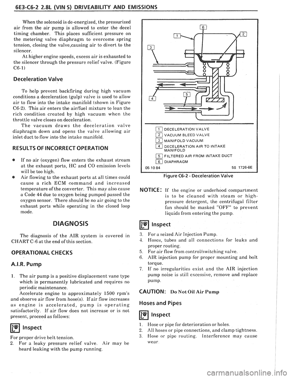
To help prevent backfiring during high vacuum
conditions a deceleration (gulp) valve is used to allow
air to flow into the intake manifold (shown in Figure
C6-2). This air enters the airlfuel mixture to lean the
rich condition created by high vacuum when the
throttle valve closes on deceleration.
The vacuum draws the deceleration valve
diaphragm down and opens the valve allowing air
inlet duct to flow into the intake manifold.
RESULTS OF INCORRECT OPERATION
@ If no air (oxygen) flow enters the exhaust stream
at the exhaust ports, HC and
CO emission levels
will be too high.
@ Air flowing to the exhaust ports at all times could
cause
a rich ECM command and increased
temperature of the converter. This may also cause
a Code
44 due to oxygen being pumped passed the
oxygen sensor. There should be no air going to the
exhaust ports while operating in the closed loop
mode.
DIAGNOSIS
The diagnosis of the AIR system is covered in
CHART C-6 at the end of this section.
OPERATIONAL CHECKS
A.I.R. Pump
1. The air pump is a positive displacement vane type
which is permanently lubricated and requires no
periodic maintenance.
Accelerate engine to approximately
1500 rpm's
and observe air flow from
hose(s). If air flow increases
as engine is accelerated, pump is operating
satisfactorily. If air flow does not increase or is not
present, proceed as follows:
Inspect
For proper drive belt tension.
2. For a leaky pressure relief valve. Air may he
heard leaking with the pump running.
DECELERATION VALVE
1 VACUUM BLEED VALVE
1 MANIFOLD VACUUM
1 DECELERATION AIR TO INTAKE
MANIFOLD
1 FILTERED AIR FROM INTAKE DUCT
/ DIAPHRAGM
05 10 84 5s 1726-6E
Figure C6-2 - Deceleration Valve
NOTICE: If the engine or underhood compartment
is to he cleaned with
steam or high-
pressure detergent, the centrifugal filter
fan should be masked "OFF7' to prevent
liquids from entering the pump.
Inspect
3. For a seized Air Injection Pump.
3. Hoses, tubes and all connections for leaks and
proper routing.
5, For air flow from controllswitching valve.
6. AIR injection pump for proper mounting and bolt
torque.
7. If no irregularities exist and the AIR injection
pump noise is still excessive, remove and replace
pump.
CAUTION: Do Not Oil Air Pump
Hoses and Pipes
Inspect
1. Hose or pipe for deterioration or holes.
2. All hoses or pipe connections, and clamp tightness.
3. Hose or pipe routing. Interference may cause
wear
Page 778 of 1825
DRIVEABILITY AND EMISSIONS 2.8L (VIN 5) 6E3-C7-1
SECTION C7
EXHAUST GAS RECIRCULATION (EGR) SYSTEM
CONTENTS
GENERAL DESCRIPTION ................ C7-1
PURPOSE
......................... C7-1
OPERATION
....................... C7-1
ELECTRONIC VACUUM REGULATOR
VALVE
........................... C7-1
PORT EGR VALVE
................... C7-2
EGR VALVE IDENTIFICATION..
......... C7-2
RESULTS OF INCORRECT OPERATION
... C7-2
DIAGNOSIS
......................... C7-3
GENERAL DESCRIPTION
PURPOSE
The EGR system is used to lower NO, (oxides of
nitrogen) emission levels caused by high combustion
temperature. It does this
by decreasing combustion
temperature.
The main element of the system is the
EGR valve
operated by vacuum and mounted
"ON" the intake
manifold.
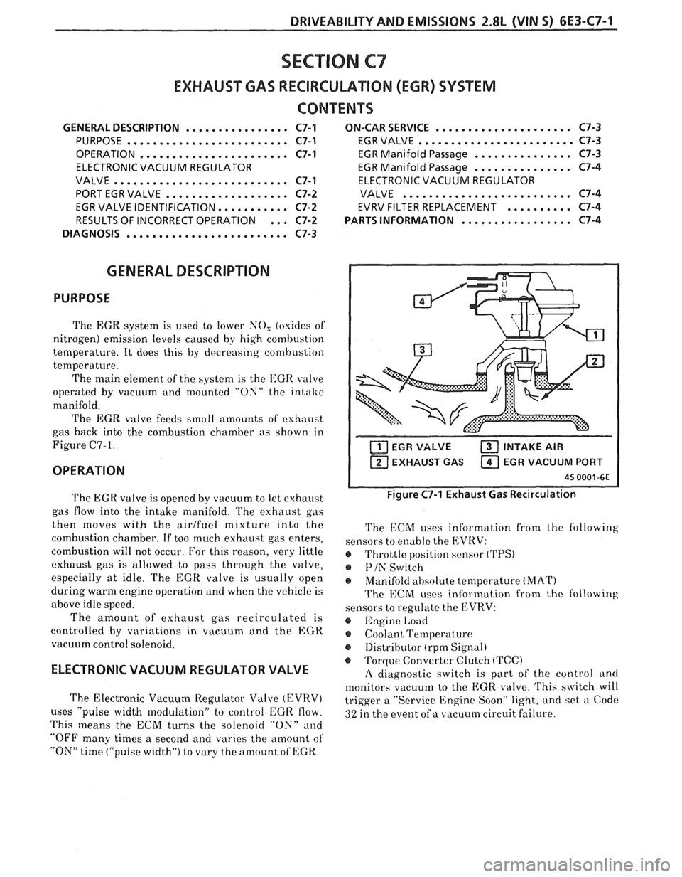
The EGR valve feeds small
amounts of exhaust
gas back into the combustion chamber as shown in
Figure C7-1.
OPERATION
..................... ON-CAR SERVICE C7-3
EGR VALVE
........................ C7-3
EGR Manifold Passage
............... C7-3
EGR Manifold Passage
............... C7-4
ELECTRONIC VACUUM REGULATOR
VALVE
.......................... C7-4
EVRV FILTER REPLACEMENT
.......... C7-4
................. PARTS INFORMATION C7-4
EGR VALVE INTAKE AIR
1 EXHAUST GAS EGR VACUUM PORT I
The EGR valve is opened by vacuum to let exhaust
gas flow into the intake manifold.
l'he exhaust gas
then moves
witb the airlfuel mixture into the
combustion chamber. If too much exhaust gas enters,
combustion will not occur. For this reason, very little
exhaust gas is allowed to pass through the valve,
especially at idle. The
EGR valve is usually open
during warm engine operation and when the vehicle is
above idle speed.
The amount of exhaust gas recirculated is
controlled by variations in vacuum and the EGR
vacuum control solenoid.
ELECTRONIC VACUUM REGULATOR VALVE
The Electronic Vacuum Regulator Valve (EVRV)
uses "pulse width modulation" to control EGK flow.
This
means the ECM turns the solenoid "ON" and
"OFF many times a second and varies the amount of
"ON" time ("pulse width") to vary the amount ot'HGK.
Figure C7-1 Exhaust Gas Recirculation
The i1:CM uses information from the following
sensors to enable the EVRV:
@ Throttle position sensor ('I'PS)
@ Plh' Switch
Manifold
ahsolute temperature (MArI')
The ECM uses information from the following
sensors to regulate the EVRV:
@ Engine 1,oad
Coolant Temperature
@ 1)istributor (rpm Signal)
@ Torque Converter Clutch (TCC)
A diagnostic switch is part of the control and
monitors vacuum to the
EGK. valve. 'I'his switch will
trigger a "Service Engine Soon" light, and set a Code
ai ure. 32 in the event of a vacuum circuit f 'I
Page 822 of 1825
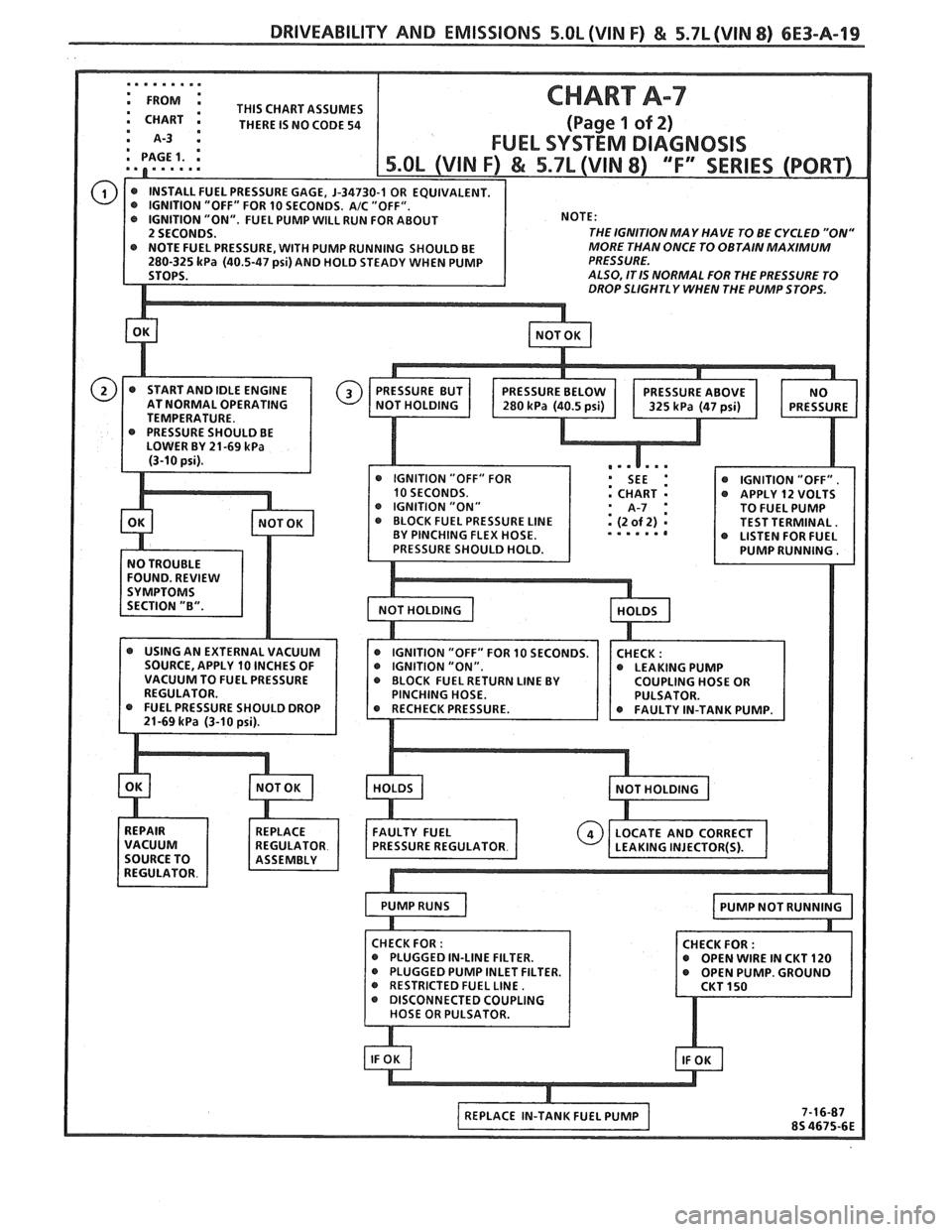
: THIS CHART ASSUMES a CHART m THERE IS NO CODE 54
m PAGE 1.
THE IGNITION MA Y HA
VE TO BE CYCLED "ON"
RESSURE, WITH PUMP RUNNING SHOULD BE MORE
THAN ONCE TO OBTAIN MAXIMUM
(40.5-47 psi) AND HOLD STEADY WHEN PUMP PRESSURE.
ALSO, ITlS NORMAL FOR THE PRESSURE TO DROP SLIGHT1 Y WHEN THE PUMP STOPS.
10 SECONDS.
...... I
@ LEAKING PUMP
@ PLUGGED PUMP INLET FILTER.
RESTRICTED FUEL LINE.
Page 823 of 1825
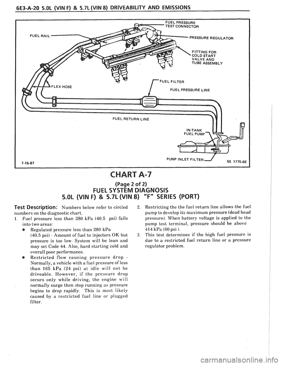
TEST CONNECTOR PRESSURE REGULATOR
COLD START
VALVE AND
TUBE ASSEMBLY
FUEL PRESSURE
LINE
PUMP INLET FlLTE
CHART A-7
(Page 2 of 2)
FUEL SYSTEM DIAGNOSIS
5.OL (VIN F) & 5.7L (VIN 8) "F" SERIES (PORT)
Test Description: Numbers below refer to circled
numbers on the diagnostic chart.
1. Fuel pressure less than 280 kPa (40.5 psi) falls
into two areas:
Regulated pressure less than
280 kPa
(40.5 psi) - Amount of fuel to injectors OK but
pressure is too low. System will be lean and
may set Code
44. Also, hard starting cold and
overall poor performance.
@ Restricted flow causing pressure drop -
Normally, a vehicle with a fuel pressure of less
than
165 kPa (24 psi) at idle will not be
driveable. However, if the pressure drop
occurs only while driving, the engine will
normally surge then stop running
as pressure
begins to drop rapidly. This is most likely
caused by
a restricted fuel line or plugged
filter.
2. Restricting the the fuel return line allows the fuel
pump to develop its maximum pressure (dead head
pressure). When battery voltage is applied to the
pump
tesl terminal, pressure should be above
414 kPa (60 psi ).
3. This test determines if the high fuel pressure is
due to
a restricted fuel return line or a pressure
regulator problem.