1988 PONTIAC FIERO fuel filter
[x] Cancel search: fuel filterPage 581 of 1825
6E2-C2-6 DRIVEABILITY AND EMISSIONS - S.OL (VIN E)
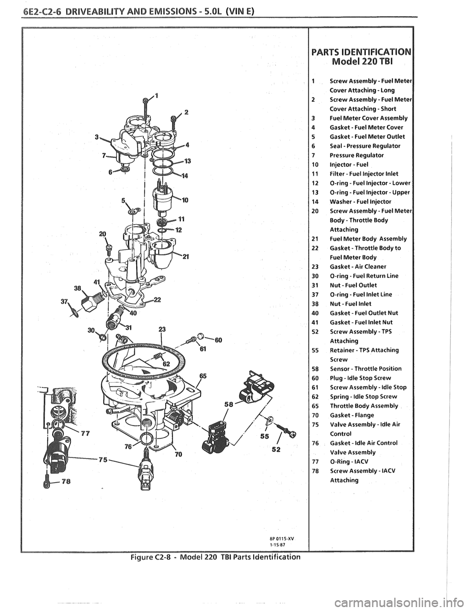
PARTS
M
IDENTIFICATION
ode1 220 TBI
Screw Assembly - Fuel Mete1
Cover Attaching - Long
Screw Assembly
- Fuel Mete1
Cover Attaching - Short
Fuel Meter Cover Assembly
Gasket
- Fuel Meter Cover
Gasket
- Fuel Meter Outlet
Seal
- Pressure Regulator
Pressure Regulator
Injector
- Fuel
Filter
- Fuel lnjector lnlet
O-ring
- Fuel lnjector - Lower
O-ring
-Fuel lnjector - Upper
Washer
- Fuel lnjector
Screw Assembly - Fuel Metel
Body - Throttle Body
Attaching
Fuel Meter Body Assembly
Gasket -Throttle Body to
Fuel Meter Body
Gasket
- Air Cleaner
O-ring
- Fuel Return Line
Nut
- Fuel Outlet
O-ring
- Fuel lnlet Line
Nut
- Fuel lnlet
Gasket
- Fuel Outlet Nut
Gasket
- Fuel lnlet Nut
Screw Assembly
- TPS
Attaching Retainer
- TPS Attaching
Screw
Sensor
- Throttle Position
Plug
-Idle Stop Screw
Screw Assembly
- ldle Stop
Spring
- ldle Stop Screw
Throttle Body Assembly
Gasket
- Flange
Valve Assembly
- ldle Air
Control
Gasket
- ldle Air Control
Valve Assembly
0-Ring
- IACV
Screw Assembly
- IACV
Attaching
8P 0115-XV
Figure C2-8 - Model 220 TBI Parts Identification
Page 583 of 1825
6E2-CZ-8 DRIVEABILITY AND EMISSIONS - 5.OL (VIN E)
a FUEL METER COVER A~ACHING SCREW ASSEMBLY - LONG
2 FUEL MmEW COVER AmAC#ING SCREW
ASSEMBLY - SHORT
1 FUEL MmEW COVER GASKET
FUEL METER BODY ASSEMBLY
a THROTTLE BODY /ASSEMBLY
FUEL MnER OUTL- GASKET
PRESSURE
REGUUTOR SUL
FUEL METER COVER ASSEMBLY
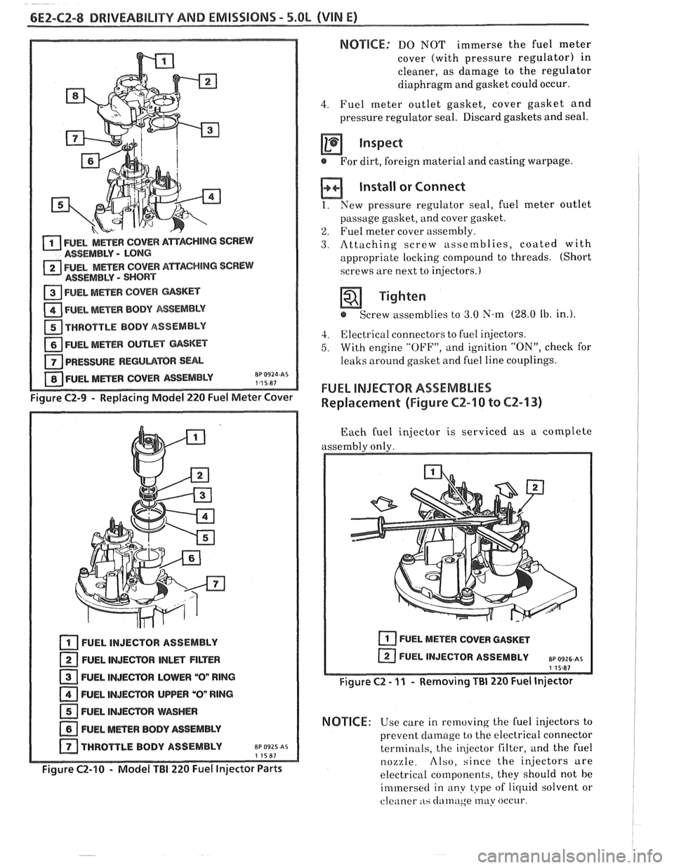
Figure C2-9 - Replacing Model 220 Fuel Meter Cover
FUEL INJECTOR ASSEMBLY
FUEL INJECTOR
lNLm FILTER
FUEL INJECTOR LOWER
"On RlNG
FUEL INJECTOR UPPER "On RlNG
FUEL INJEmR WASHER
NEL METER BODY ASSEMBLY
THROTTLE BODY ASSEMBLY
EP 0925 AS 11587
Figure C2-10 - Model TBI 220 Fuel Injector Parts
NOTSCE: DO NOT immerse the fuel meter
cover (with pressure regulator) in
cleaner, as damage to the regulator
diaphragm and gasket could occur.
4. Fuel meter outlet gasket, cover gasket and
pressure regulator seal. Discard gaskets and seal.
inspect
@ For dirt, foreign material and casting warpage.
Install or Connect
I. New pressure regulator seal, fuel meter outlet
passage gasket, and cover gasket.
'2. Fuel meter cover assembly.
3. Attaching screw assetnblies, coated with
appropriate locking compound to threads. (Short
screws are next to injectors.)
Tighten
e Screw assemblies to 3.0 N.m (28.0 Ib. in.).
4. Electrical connectors to fuel injectors.
5. With engine "OFF", and ignition "ON", check for
leaks around gasket and fuel line couplings.
FUEL INJECTOR ASSEMBLIES
Replacement (Figure CZ-10 to CZ-13)
Each fuel injector is serviced as a complete
assembly only.
FUEL METER COVER GASKET
I Figure C2 - 11 - Removing Ti31 220 Fuel Injector
NOTICE: Use care in removing the Cuel injectors to
prevent
clamage to the electrical connector
terminals, the
in,jector filter, and the fuel
nozzle. Also, since the injectors are
electrical components, they should not be
immersecl in any type of lirluid solvent or
cleaner
as clatnuge may occur.
Page 584 of 1825
DRIVEABILITY AND EMISSIONS - 5.OL (VIN El CEZ-C2-9
u PART IDENTIFICATION NUMBER
VENDOR IDENTlFlCATl
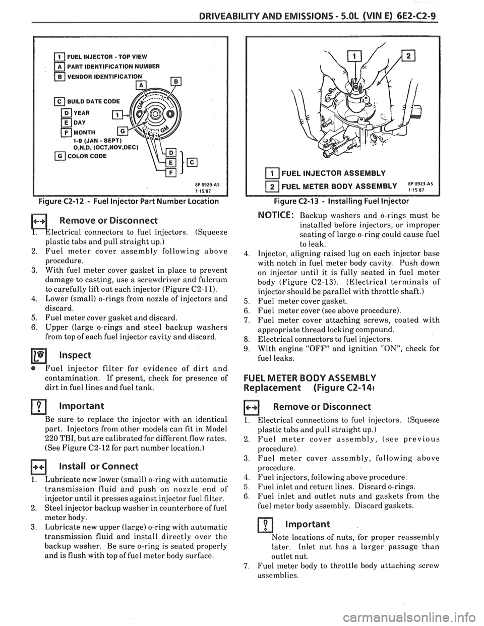
Figure C2-12 - Fuel Injector Part Number Location
Remove or Disconnect
lectrical connectors to fuel injectors. (Squeeze
plastic tabs and pull straight
up.)
2. Fuel meter
cover assembly following above
procedure.
3. With fuel meter cover gasket in place to prevent
damage to casting, use a screwdriver and fulcrum
to carefully lift out each injector (Figure
C2-11).
4. Lower (small) o-rings from nozzle of injectors and
discard.
5. Fuel meter cover gasket and discard.
6. Upper (large o-rings and steel backup washers
from top of each fuel injector cavity and discard.
Inspect
@ Fuel injector filter for evidence of dirt and
contamination.
If present, check for presence of
dirt in fuel lines and fuel tank.
Important
Be sure to replace the injector with an identical
part. Injectors from other models can fit in Model
220 TBI, but are calibrated for different flow rates.
(See Figure
C2-12 for part number location.)
Install or Connect
1. Lubricate new lower (small) o-ring with automatic
transmission fluid and push on nozzle end of
injector until it presses against
in,jector fuel filter.
2. Steel injector backup washer in counterbore of fuel
meter body.
3. Lubricate new upper (large) o-ring with automatic
transmission fluid and install directly over
the
backup washer. Be sure o-ring is seated properly
and is flush with top of fuel meter body surface.
I I 1 I FUEL INJECTOR ASSEMBLY
FUEL METER BODY ASSEMBLY
~p,~9~~~As
Figure C2-13 - Installing Fuel Injector
NOTICE: Backup washers and o-rings must be
installed before injectors, or improper
seating of large o-ring
could cause fuel
to leak.
4. Injector, aligning raised lug on each injector base
with notch in fuel meter body cavity. Push down
on injector until it is fully seated in fuel meter
body (Figure
C2-13). (Electrical terminals of
injector should be parallel with throttle shaft.)
5. Fuel meter cover gasket.
6. Fuel meter cover (see above procedure).
7. Fuel meter cover attaching screws, coated with
appropriate thread locking compound.
8. Electrical connectors to fuel injectors.
9. With engine "OFF" and ignition "ON", check for
fuel leaks.
FUEL METER BODY ASSEMBLY
Replacement (Figure
CZ-14)
a Remove or Disconnect
1. Electrical connections to fuel injectors. (Squeeze
plastic tabs and pull straight up.)
2. Fuel meter cover assembly, (see previous
procedure).
3. Fuel
meter cover assembly, following above
procedure.
4. Fuel injectors, following above procedure.
5. Fuel inlet and return lines. Discard o-rings.
6. Fuel inlet and outlet nuts and gaskets from the
fuel meter body assembly. Discard gaskets.
Important
Note locations of nuts, for proper reassembly
later. Inlet nut has a larger passage than
outlet nut.
7. Fuel meter body to throttle body attaching screw
assemblies.
Page 612 of 1825
DRIVEABILITY AND EMISSIONS 5.OL (VIN E) 6EZ-C6-1
SECTION C6
AIR INJECTION REACTION (A.I.R.) SYSTEM
CONTENTS
GENERAL DESCRIPTION ............... C6-1
PURPOSE ......................... C6-1
OPERATION ...................... C6-1
AIR CONTROL PEDES VALVE .......... C6-1
RESULTS OF INCORRECT OPERATION .... C6-2
DIAGNOSIS
........................ C6-2
OPERATIONAL CHECKS .............. C6-2
AirPump ...................... C6-2
Hoses and Pipes ................. C6-3
GENERAL DESCRIPTION
PURPOSE
The A.I.R. system helps reduce hydrocarbon (HC),
carbon monoxide (CO), and oxides of nitrogen (NO,)
exhaust emissions. It also heats up the catalytic
converter quickly on engine start-up so conversion of
exhaust gases can occur sooner.
A Dual bed converter is used. It consists of a three
way catalyst (which controls all three emissions) in
series with
a two way catalyst (which controls only HC
and
CO) both are in one housing. A pipe between the
two converters allows air to be injected into the second
(two way) converter to increase its efficiency to further
control
HC and CO (Figure C6-1).
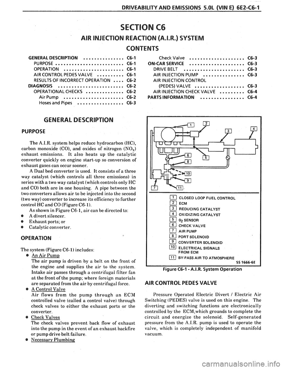
As shown in Figure C6-1, air can be directed to:
@ A divert silencer.
@ Exhaust ports; or
@ Catalytic converter.
OPERATION
The system (Figure C6-1) includes:
@ An Air Pump
The air pump is driven by a belt on the front of
the engine and supplies the air to the system.
Intake air passes through a centrifugal filter fan
at the front of the pump; where foreign materials
are separated from the air
by centrifugal force.
@ A Control Valve
Air flows from the pump through an ECM
controlled valve (called a control valve) through
check valves to either the exhaust ports or the
converter.
@ Check Valves
The check valves prevent back flow of exhaust
into the pump in the event of an exhaust backfire
or pump drive belt failure.
@ Necessary Plumbing
Check Valve .................... C6-3
ON-CAR SERVICE
.................... C6-3
DRIVEBELT ...................... C6-3
AIR INJECTION PUMP ............... C6-3
AIR INJECTION CONTROL
(PEDES) VALVE
.................. C6-3
AIR INJECTION CHECK VALVE ......... C6-4
PARTS INFORMATION
................ C6-4
CLOSED LOOP FUEL CONTROL
ECM
1 REDUCING CATALYST - 1 OXlDlZlNG CATALYST
1 5 SENSOR
CHECK VALVE
1 AIR PUMP
1 PORT SOLENOID
CONVERTER SOLENOID
/ ELECTRICAL SIGNALS
FROM ECM
BY-PASS AIR TO ATMOSPHERE
Figure C6-1 - A.I.R. System Operation
AIR CONTROL PEDES VALVE
Pressure Operated Electric Divert / Electric Air
Switching (PEDES) valve is used on this engine. The
diverting and switching functions are electronically
controlled by the
ECM,which grounds to complete the
circuit and energize the solenoid. Self-generated
pressure from the A.I.R. pump is used to operate the
valve, which is completely independent of manifold
vacuum.
Page 649 of 1825
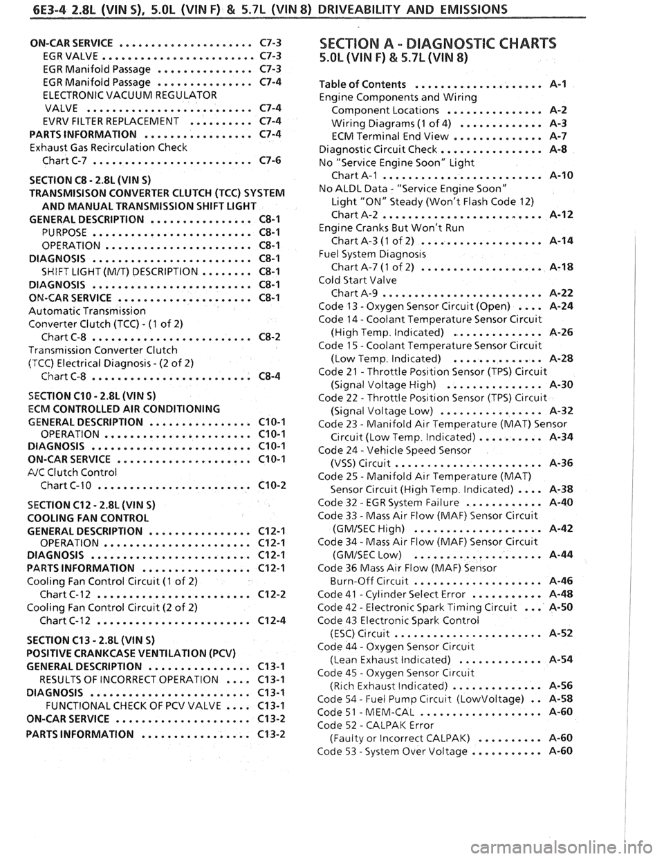
6E3-4 2.8L (VIN S) . 5.OL (VIN F) & 5.7L (VIN 8) DRIVEABILITY AND EMISSIONS
ON-CAR SERVICE ..................... C7-3
EGRVALVE
........................ C7-3
EGR Manifold Passage
............... C7-3
EGR Manifold Passage
............... C7-4
ELECTRONIC VACUUM REGULATOR
VALVE
.......................... C7-4
EVRV FILTER REPLACEMENT
.......... C7-4
PARTS INFORMATION
................. C7-4
Exhaust Gas Recirculation Check
Chart C-7
......................... C7-6
SECTION
C8 . 2.8L (VIN S)
TRANSMISISON CONVERTER CLUTCH (TCC) SYSTEM
AND MANUAL TRANSMISSION SHIFT LIGHT
GENERAL DESCRIPTION
................ C8-1
PURPOSE ......................... C8-1
OPERATION ....................... C8-1
DIAGNOSIS
......................... C8-1
SHIFT LIGHT (M/T) DESCRIPTION ........ C8-1
DIAGNOSIS
......................... C8-1
ON-CAR SERVICE ..................... C8-1
Automatic Transmission
Converter Clutch (TCC)
. (1 of 2)
Chart C-8
......................... C8-2
Transmission Converter Clutch
(TCC) Electrical Diagnosis
. (2 of 2)
Chart C-8
......................... C8-4
SECTION C10 . 2.8L (WIN S)
ECM CONTROLLED AIR CONDITIONING
GENERAL DESCRIPTION
................ C10-1
OPERATION ....................... C10-1
DIAGNOSIS ......................... C10-1
ON-CARSERVICE ..................... C10-1
FJC Clutch Control
Chart C-
1 0 ........................ C10-2
SECTION C12 . 2.8L (VlN S)
COOLING FAN CONTROL
GENERAL DESCRIPTION
................ C12-1
OPERATION ....................... C12-1
DIAGNOSIS
......................... C12-1
PARTS INFORMATION ................. C12-1
Cooling Fan Control Circuit (1 of 2)
Chart
C- 12 ........................ C12-2
Cooling Fan Control Circuit (2 of 2)
Chart C-12
........................ C12-4
SECTION C13
. 2.8L (WIN S)
POSITIVE CRANKCASE VENTILATION (PCV)
GENERAL DESCRIPTION
................ C13-1
RESULTS OF INCORRECT OPERATION
.... C13-1
DIAGNOSIS
......................... C13-1
FUNCTIONALCHECK OF PCV VALVE .... C13-1
ON-CAR SERVICE
..................... C13-2
PARTS INFORMATION
................. C13-2
SEC"T0N A . DIAGNOSTIC CHARTS
5.OL (VIN F) & 5.7L (VIN 8)
.................... Table of Contents A-1
Engine Components and Wiring
............... Component Locations A-2
Wiring Diagrams
(1 of 4) ............. A-3
ECM Terminal End View
.............. A-7
Diagnostic Circuit Check
................ A-8
No "Service Engine Soon" Light
......................... Chart A-1 A-10
No ALDL Data
. "Service Engine Soon"
Light "ON" Steady (Won't Flash Code 12)
Chart A-2
......................... A-12
Eng~ne Cranks But Won't Run
Chart A-3
(1 of 2) ................... A-14
Fuel System
Diagnos~s
Chart A-7 (1 of 2) ................... A-18
Cold Start Valve
Chart A-9
......................... A-22
Code 13
. Oxygen Sensor Circuit (Open) .... A-24
Code 14
. Coolant Temperature Sensor Circuit
(High Temp
. Indicated) .............. A-26
Code
1 5 . Coolant Temperature Sensor C~rcuit
. .............. (Low Temp Ind~cated) A-28
Code 21
. Throttle Pos~tlon Sensor (TPS) Circuit
(Signal Voltage High)
............... A-30
Code 22
. Throttle Pos~t~on Sensor (TPS) Circuit
................ (Signal Voltage Low) A-32
Code 23
. Manifold Air Temperature (MAT) Sensor
C~rcuit (Low Temp . Indicated) .......... A-34
Code 24
. Vehicle Speed Sensor
....................... (VSS) Circuit A-36
Code 25
. Manifold Air Temperature (MAT)
Sensor Circuit (High Temp
. Indicated) .... A-38
. ............ Code 32 EGR System Failure A-40
Code 33
. Mass Air Flow (MAF) Sensor Circuit
.................... (GMISECHlgh) A-42
Code 34
. Mass Air Flow (MAF) Sensor Circu~t
.................... (GMISEC Low) A-44
Code 36 Mass Air Flow
(MAF) Sensor
.. ..... ........... Burn-Off Circuit , , A-46
. ........... Code 41 Cyl~nder Select Error A-48
... . Code 42 Electronic Spark Timing Circuit A-50
Code 43 Electronic Spark Control
(ESC)
C~rcuit ....................... A-52
Code 44
. Oxygen Sensor Circu~t
(Lean Exhaust lnd~cated) ............. A-54
Code 45
. Oxygen Sensor Circuit
(Rich Exhaust Indicated)
.............. A-56
Code 54
. Fuel Pump C~rcuit (Lowvoltage) . . 14-58
. ................... Code 51 MEM-CAL A-60
Code 52
. CALPAK Error
.......... (Faulty or Incorrect CALPAK) A-60
. ........... Code 53 System Over Voltage A-60
Page 671 of 1825
6E3-A-I8 2.8b (VIN 5) DRIVEABILITY AND EMISSIONS
PUMP INLET FILTER
IN-TANK PUMP
FUEL
PRESSURE CONNECTOR
CHART A-7
(Page 4 of 2)
FUEL SYSTEM DsAGNOSBS
2.8L (VIN S) ""FYSERBES (PORT)
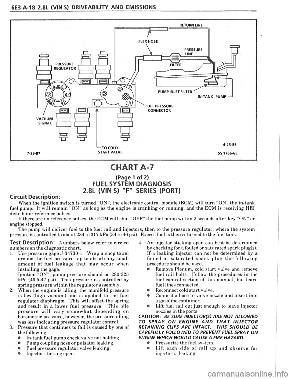
Circuit Description:
When the ignition switch is turned "ON", the electronic control module (ECM) will turn "ON" the in-tank
fuel pump. It will remain "ON" as long as the engine is cranking or running, and the ECM is receiving
HE1
distributor reference pulses.
If there are no reference pulses, the ECM will shut "OFF" the fuel pump within
2 seconds after key "ON" or
engine stopped.
The pump will deliver fuel to the fuel rail and injectors, then to the pressure regulator, where the system
pressure is controlled to about 234 to 317
kPa (34 to 46 psi). Excess fuel is then returned to the fuel tank.
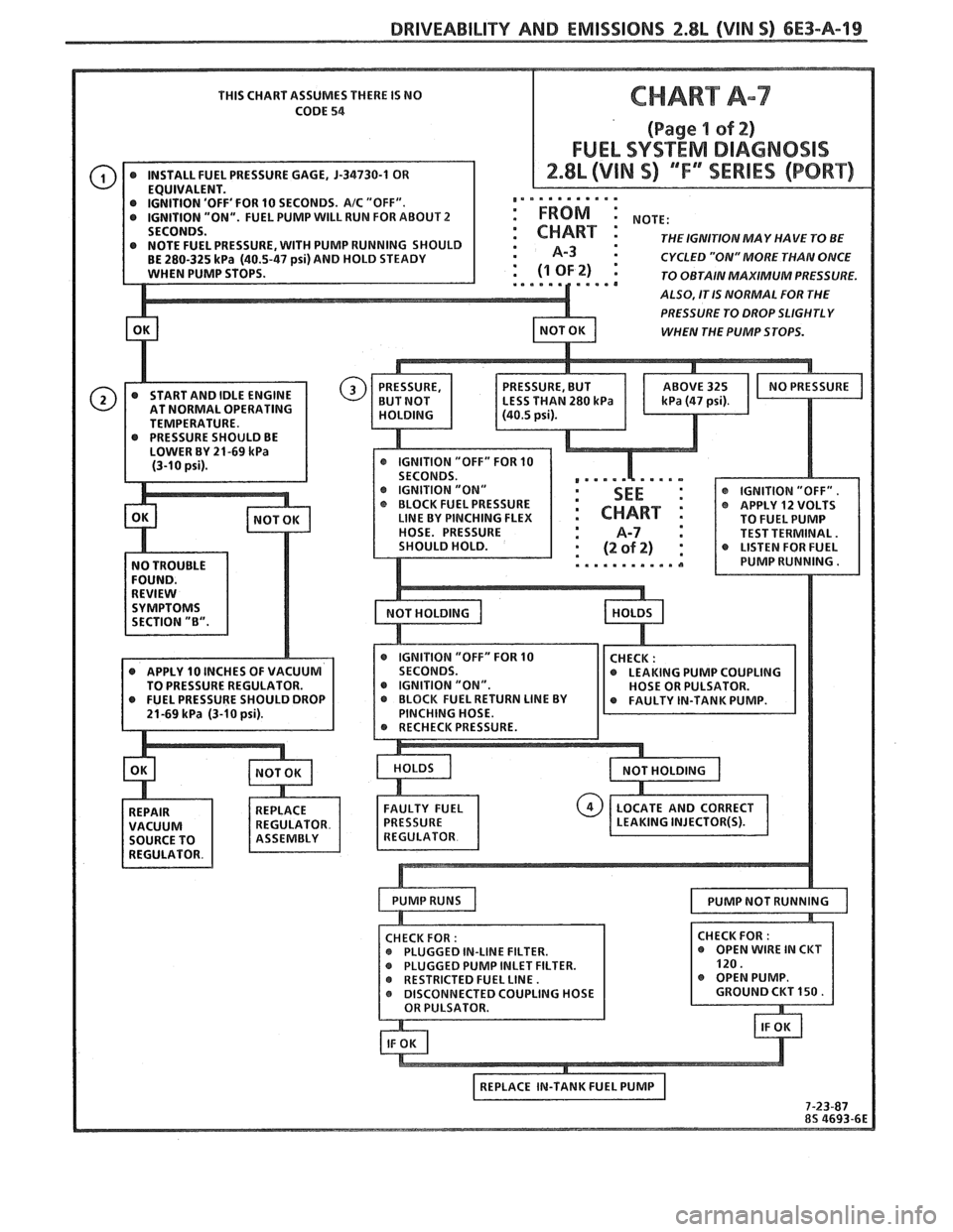
Test Description: Numbers below refer to circled
numbers on the diagnostic chart.
1. Use pressure gage 5-34730-1. Wrap a shop towel
around the fuel pressure tap to absorb any small
amount of fuel leakage that
may occur when
installing the gage.
Ignition "ON", pump pressure should be 280-325
kPa (40.5-47 psi). This pressure is controlled by
spring pressure within the regulator assembly.
2. When the engine is idling, the manifold pressure
is low (high vacuum) and is applied to the fuel
regulator diaphragm. This will offset the spring
and result in a lower fuel pressure.
'This idle
pressure will vary somewhat depending on
barometric pressure, however, the pressure idling
was less indicating pressure regulator control.
3. Pressure that continues to fall is caused by one of
the following:
In-tank fuel pump check valve not holding.
@ Pump coupling hose or pulsator leaking.
Fuel pressure regulator valve leaking.
@ Injector sticking open. 4.
An injector sticking open can best be determined
by checking for a fouled or saturated spark
plug(s).
If a leaking injector can not be determined by a
fouled or saturated spark plug the following
procedure should be used.
e Remove Plenum, cold start valve and remove
fuel rail bolts. Follow the procedures in the
fuel control section of this manual, but leave
fuel lines connected.
@ Reconnect cold start valve.
@ Connect a hose to valve nozzle and insert into
a gasoline container.
@ Lift fuel rail out just enough to leave injector
nozzles in the ports.
CAUTION: BE SURE INJEePOR(S) ARE NOT ALLOWED
PO SPRAY ON ENGINE AND THAT INJECTOR
RETAINING
CLIPS ARE INTACT. PHIS SHOULD BE
CAREFULLY
FOLLOWD PO PREVENT FUEL SPRAY ON'
ElZIGlNE WHICH WOULD CAUSE A FIRE HAZARD.
@ Pressurize the fuel system.
@ I.if't each side of rail up and observe for
injc~ctot-l.) It.ulting
Page 672 of 1825
DRIVEABILITY AND EMISSIONS 2.8L (VIN S) 6E3-A-19
THIS CHART ASSUMES THERE IS NO
CODE
54
'OFF' FOR 10 SECONDS. AIC "OFF". ,,. . . . . . . . .'.
"ON". FUEL PUMP WILL RUN FOR ABOUT 2 : FROM :
THE IGNITIONMAY HAVE TO BE : A-3 : CYCLED "ON" MORE THAN ONCE
TO OBTAIN MAXIMUM PRESSURE.
ALSO, IT IS NORMAL FOR THE
PRESSURE TO DROP SLIGHTLY
WHEN THE PUMP STOPS.
AT NORMAL OPERATING
TEMPERATURE.
IGNITION "ON"
@ IGNITION "OFF".
BLOCK FUEL PRESSURE @ APPLY 12 VOLTS LINE BY PINCHING FLEX
TO FUEL PUMP
HOSE. PRESSURE TEST TERMINAL.
@ IGNITION "OFF" FOR 10 @ APPLY 10 INCHES OF VACUUM
LEAKING PUMP COUPLING
TO PRESSURE REGULATOR. @ IGNITION "ON".
INLET FILTER.
Page 673 of 1825
6E3-A-28 2.8b (VIN 9) DRIVEABILITY AND EMISSIONS
PUMP INLET FILTER
IN-TANK PUMP
FUEL PRESSURE CONNECTOR
CHART A-7
(Page 2 sf 2)
FUEL SYSTEM DIAGNOSIS
2.8L (VIN S) ""FYSEWlES (PORT)
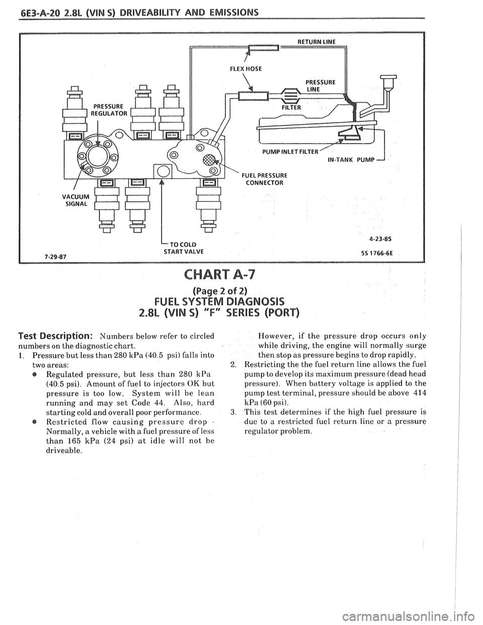
Pest Description: Numbers below refer to circled
numbers on the diagnostic chart.
1. Pressure but less than 280
kPa (40.5 psi) falls into
two areas:
@ Regulated pressure, but less than 280 kPa
(40.5 psi). Amount of fuel to injectors OK but
pressure is too low. System will be lean
running and may set Code 44. Also, hard
starting cold and overall poor performance.
Restricted flow causing pressure drop
-
Normally, a vehicle with a fuel pressure of less
than 165
kPa (24 psi) at idle will not he
driveable. However,
if the pressure drop occurs only
while driving, the engine will normally surge
then stop as pressure begins to drop rapidly.
2. Restricting the the fuel return line allows the fuel
pump to develop its
maximum pressure (dead head
pressure). When battery voltage
is applied to the
pump test terminal, pressure should be above 414
kPa (60 psi).
3. This test determines if the high fuel pressure is
due to a restricted fuel return line or a pressure
regulator problem.