1988 PONTIAC FIERO oil
[x] Cancel search: oilPage 631 of 1825
6E2-C8-6 DRIVEABILITY AND EMISSIONS - 5.OL (VIN E)
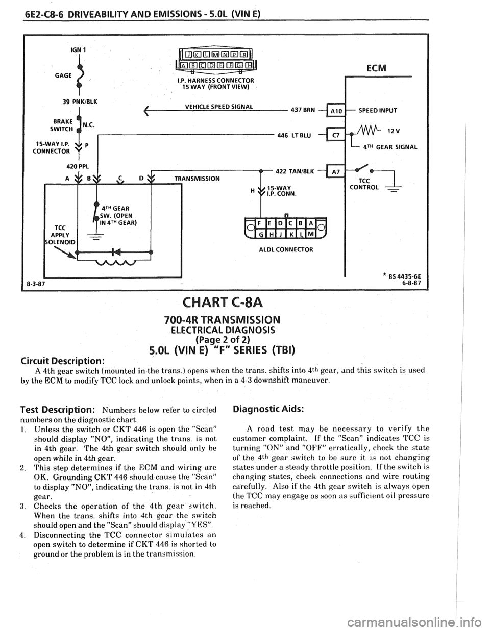
I.P. HARNESS CONNECTOR 15 WAY (FRONT VIEW)
ECM
VEHICLE SPEED SIGNAL
SPEED INPUT
4TH GEAR SIGNAL
422 TANIBLK
ALDL CONNECTOR
* 85 4435-66 6-8-87
CHART C-8A
700-4R TRANSMISSION
ELECTRICAL DIAGNOSIS
(Page 2 of 2)
5.0L (VIN E) "F" "SERIES (TBI)
Circuit Description:
A 4th gear switch (mounted in the trans.) opens when the trans. shifts into 4th gear, and this switch is used
by the ECM to modify TCC lock and unlock points, when in a 4-3 downshift maneuver.
Test Description: Numbers below refer to circled
numbers on the diagnostic chart.
1. Unless the switch or CKT 446 is open the "Scan"
should display "NO", indicating the trans. is not
in 4th gear.
The 4th gear switch should only he
open whiie in 4th gear.
2. This step determines if the ECM and wiring are
OK. Grounding CKT 446 should cause the "Scan"
to display "NO", indicating the trans. is not in 4th
gear.
3. Checks the operation of the 4th gear switch.
When the trans. shifts into 4th
geir the switch
should open and the "Scan" should display
"YES".
4. Disconnecting the TCC connector simulates an
open switch to determine if CKT
446 is shorted to
ground or the problem is in the transmission.
Diagnostic Aids:
A road test may be necessary to verify the
customer complaint. If the "Scan" indicates TCC is
turning
"ON" and "OFF" erratically, check the state
of the 4th gear switch to he sure it is not changing
states under a steady throttle position.
If the switch is
changing states, check connections and wire routing
carefully. Also if the 4th gear switch is always open
the
TCC may engage as soon as sufficient oil pressure
is reached.
Page 636 of 1825
DRIVEABILITY AND EMISSIONS - 5.OL (VIN E) 6E2-CI 3-1 --
SECTION C13
POSI"BVE CRANKCASE VENTILATION (PCV)
CONTENTS
GENERAL DESCRIPTION ............*.. C13-1 ON-CARSERVICE .................... C13-2
DIAGNOSIS
.*.....................* C13-1 PARTSINFORMATION...,............. C13-2
RESULTS OF INCORRECT OPERATION ... C13-1
GENERAL DESCRIPTION
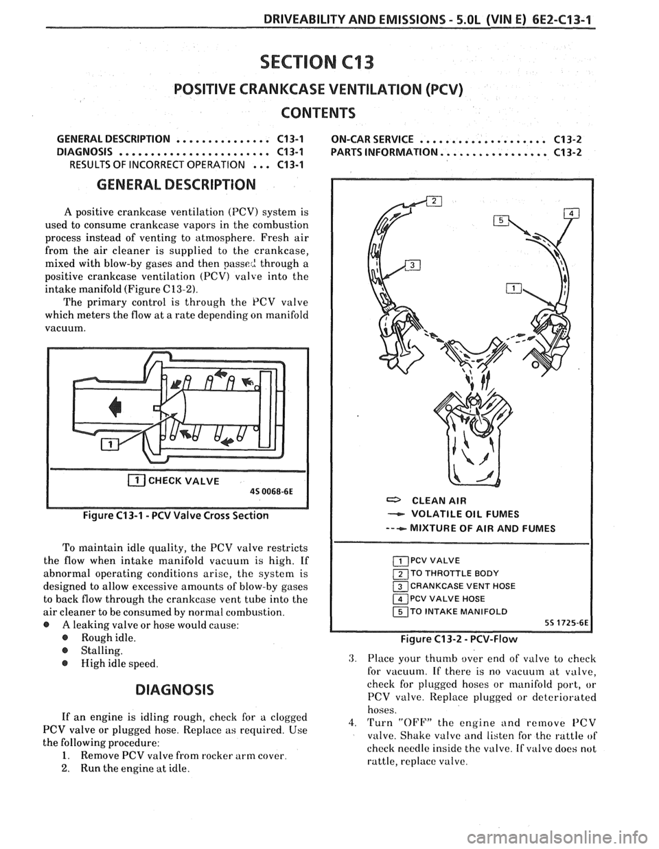
A positive crankcase ventilation (PCV) system is
used to consume crankcase vapors in the combustion
process instead of venting to atmosphere. Fresh air
from the air cleaner is supplied to the crankcase,
mixed with blow-by gases and then
passe2 through a
positive crankcase ventilation
(PCV) valve into the
intake manifold (Figure
C13-2).
The primary control is through the PCV valve
which meters the flow at a rate depending on manifold
vacuum.
CHECKVALVE
a CLEAN AIR
- VOLATILE OIL FUMES
--+ MIXTURE OF AIR AND FUMES
To maintain idle quality, the PCV valve restricts
the flow when intake manifold vacuum is high. If
abnormal operating conditions arise, the system is
TO THROTTLE BODY
designed to allow excessive amounts of blow-by gases CRANKCASE VENT HOSE
to back flow through the crankcase vent tube into the PCV VALVE HOSE
air cleaner to be consumed by normal combustion. TO INTAKE MANIFOLD
@ A leaking valve or hose would cause:
@ Roughidle. Figure C13-2 - PCV-Flow
@ Stalling.
@ High idle speed.
DIAGNOSIS
3. Place your thumb over end of valve to check
for vacuum. If there is no
vacuuin at valve,
check for plugged hoses or manifold port, or
PCV valve. Iteplace plugged or deteriorated
hoses.
If an engine is idling rough, check for a clogged
4. Turn "OFF" the engine and remove PCV PCV valve or plugged hose. Replace as required. Use
valve. Shake valve and listen for the rattle of
the following procedure:
check needle inside the valve. If
valve does not 1. Remove PCV valve from rocker arm cover.
rattle, replace valve.
2. Run the engine at idle.
Page 637 of 1825
6E2-C"1-2 DRIVEABILITY AND EMISSIONS - 5.OL (VIN E)
With this system, any blow-by in excess of the
system capacity (from a badly-worn engine, sustained
heavy load,
etc.) is exhausted into the air cleaner and
is drawn into the engine.
Proper operation of the PCV System is dependent
upon a sealed engine. If oil sludging or dilution is
noted, and the PCV System is functioning properly,
check engine for possible cause and correct to ensure
that system will function as intended.
Results of Incorrect PCV Operation
@ A plugged valve or hose may cause:
@ Rough idle.
@ Stalling or slow idle speed.
Oil leaks.
@ Oil in air clcaner.
@ Sludge in engine.
ON-CAR SERVICE
An engine which is operated without any
crankcase ventilation can be damaged. Therefore, it is
important to replace the
PCV valve and air cleaner
breather at intervals shown in Section
"OB".
Periodically, inspect the hoses and clamps and
replace any showing signs of deterioration.
PARTS INFORMATION
PART NAME GROUP
Air Cleaner ......................... 3.402
................ Valve Asm, UCase Vent 1.745
Page 644 of 1825
INDEX
SECT ION PAGE
Diagnosis ......................... C1.5. 16
Service
........................... C1-8
MAT Sensor
General Description
.................. C1-2
Diagnosis
......................... C1-5
Service
........................... C1-7
Minimum
Idle Speed Adjustment ......... C2-14
Misses
.............................. B-4
Negative Backpressure Valve
............ C7-1
Non-Adjustable TPS Output Check
........ C2-14
Oil Pressure Switch
.................... C2-16
Oxygen Sensor
(02)
General Description ................. C1-3
Diagnosis ......................... C1-5
Service
........................... C1-9
Open Loop
.......................... C2-2
Park Neutral Switch
General Description
................. C1-4
Diagnosis
.......................... C1-5
C1-12
Service. Parts Information
............. C1-9
Poor Fuel Economy
.................... B.5.
C5- 1
Poor Performance
.................... C5-1
Positive Crankcase Ventilation (PCV)
General Description. Diagnosis
......... C13-1
Service. Parts Information
............. C13-2
Pressure Regulator
.................... C2-3
PROM General Description
................. C1-1
Diagnosis ......................... C1-5
Service
........................... C1-6
....................... Quad Drivers. C1-4
Reference Signal
...................... C1-5
Rough
Idle .......................... B-5
RunMode ........................... C2-2
SECTION PAGE
S
Sag ................................ B-4
"Scan" Data
......................... A-8
Sensor Information
.................... C1-2-9
Setting Timing
....................... C4-2
Shift Light
........................... C8-8
Sluggish
............................ B-3
Spark Knock
......................... B-4
Spongy
............................. 8-3
Stalling ............................. B-5
Starting Mode
........................ C2-1
Stumble
............................ B-4
Surges
............................. B-3
Table Of Contents
.................... A-1
Tank Pressure Control Valve
General Description
................. C3-2
Diagnosis
......................... C3-3
Throttle Body Injection Unit
General Description
................. C2-3
Service
........................... C2-7
C2- 14
Throttle Position Sensor
................ C2-5
General Description
................. C1-3
Diagnosis
......................... C1-5
Service
........................... C1-9
C2- 12
Transmission Converter Clutch TCC System
General Description
................. C8-1
Diagnosis
......................... C8-2
C8-4 C8-6
Parts Information
................... C8-2
Unstable
Idle ........................ B-5
....................... Vapor Canister C3-1
Vehicle Speed Sensor (VSS)
.................. General Description C1-4
Diagnosis
......................... 4.5
..................... Wiring Diagrams 8-3
Page 648 of 1825
DRlVEABlLlTVAND EMISSIONS 2.8L (VIN S). 5.OL (VIN F) & 5.7L (VIN 8) 6E3-3
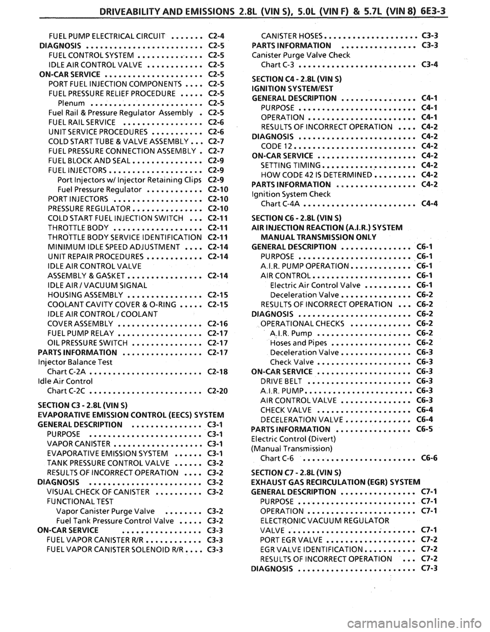
.................... FUEL PUMP ELECTRICAL CIRCUIT ....... C2-4 CANISTER HOSES C3-3
................ DIAGNOSIS ......................... C2-5 PARTS INFORMATION C3-3
FUEL CONTROL SYSTEM .............. C2-5 Canister Purge Valve Check
......................... IDLE AIR CONTROL VALVE ............ C2-5 Chart C-3 C3-4
ON-CAR SERVICE
..................... C2-5
.... PORT FUEL INJECTION COMPONENTS C2-5
FUEL PRESSURE RELIEF PROCEDURE ..... C2-5
Plenum ........................ C2-5
Fuel Rail & Pressure Regulator Assembly . C2-5
FUEL RAIL SERVICE ................. C2-6
UNIT SERVICE PROCEDURES ........... C2-6
COLD START TUBE & VALVE ASSEMBLY ... C2-7
FUEL PRESSURE CONNECTION ASSEMBLY . C2-7
FUEL BLOCK AND SEAL ............... C2-9
FUEL INJECTORS .................... C2-9
Port Injectors wl Injector Retaining Clips C2-9
Fuel Pressure Regulator ............ C2-10
PORT INJECTORS ................... C2-10
PRESSURE REGULATOR ............... C2-10
COLD START FUEL INJECTION SWITCH ...
THROTTLE BODY ...................
THROTTLE BODY SERVICE IDENTIFICATION
MINIMUM IDLE SPEED ADJUSTMENT
....
UNIT REPAIR PROCEDURES ............
IDLE AIR CONTROL VALVE
ASSEMBLY
& GASKET ................
IDLE AIR I VACUUM SIGNAL
HOUSING ASSEMBLY
................
COOLANT CAVITY COVER & O-RING .....
IDLE AIR CONTROL I COOLANT
COVER ASSEMBLY
..................
FUEL PUMP RELAY ..................
OIL PRESSURE SWITCH ...............
PARTS INFORMATION .................
Injector Balance Test
Chart C-2A
........................
Idle Air Control
Chart C-2C
........................
SECTION C3 . 2.8L (WIN S)
EVAPORATIVE EMISSION CONTROL (EECS) SYSTEM
GENERAL
DESCRIPTION ............... C3-1
PURPOSE ........................ C3-1
VAPOR CANISTER ................... C3-1
EVAPORATIVE EMISSION SYSTEM ...... C3-1
TANK PRESSURE CONTROL VALVE ...... C3-2
.... RESULTS OF INCORRECT OPERATION C3-2
DIAGNOSIS
........................ C3-2
VISUAL CHECK OF CANISTER .......... C3-2
FUNCTIONAL TEST
Vapor Canister Purge Valve
........ C3-2
..... Fuel Tank Pressure Control Valve C3-2
ON-CAR SERVICE
................. C3-3
FUEL VAPOR CANISTER WR ............ C3-3
FUEL VAPOR CANISTER SOLENOID WR .... C3-3
SECTION C4 . 2.8L (VIN S)
IGNITION
SQSTEMIEST
................ GENERAL DESCRIPTION C4-1
......................... PURPOSE C4-1
OPERATION ....................... C4-1
RESULTS OF INCORRECT OPERATION .... C4-2
DIAGNOSIS
......................... C4-2
CODE 12 .......................... C4-2
ON-CAR SERVICE ..................... C4-2
SETTING TIMING .................... C4-2
HOW CODE 42 IS DETERMINED ......... C4-2
PARTS INFORMATION ................. C4-2
Ignition System Check
Chart C-4A
........................ C4-4
SECTION C6 . 2.8L (VIN S)
AIR INJECTION REACTION (A.I.R.) SYSTEM
MANUAL TRANSMISSION ONLY
............... GENERAL DESCRIPTION C6-1
........................ PURPOSE C6-1
............. A.I.R. PUMP OPERATION C6-I
..................... AIR CONTROL C6-1
.......... Electric Air Control Valve C6-1
............... Deceleration Valve C6-2
... RESULTS OF INCORRECT OPERATION C6-2
........................ DIAGNOSIS C6-2
............. OPERATIONAL CHECKS C6-2
.................... A.I.R. Pump C6-2
................. Hoses and Pipes C6-2
............... Deceleration Valve C6-3
.................... Check Valve C6-3
.................... ON-CAR SERVICE C6-3
...................... DRIVEBELT C6-3
....................... A.I.R. PUMP C6-3
............... AIR CONTROL VALVE C6-3
.................... CHECKVALVE C6-4
DECELERATION VALVE .............. C6-4
................ PARTS INFORMATION C6-5
Electric Control (Divert)
(Manual Transmission)
........................ Chart C-6 C6-6
SECTION C7
. 2.8L (VIN S)
EXHAUST GAS RECIRCULATION (EGR) SYSTEM
GENERAL DESCRIPTION
................ C7-1
......................... PURPOSE C7-1
....................... OPERATION C7-I
ELECTRONIC VACUUM REGULATOR
........................... VALVE C7-1
................... PORT EGR VALVE C7-2
........... EGR VALVE IDENTIFICATION C7-2
... RESULTS OF INCORRECT OPERATION C7-2
......................... DIAGNOSIS C7-3
Page 651 of 1825
6E3-6 2.8L (VIN S). 5.OL (&BIN F) & 5.7L (WIN 8) BRllVEABlhlPY AND EMISSIONS
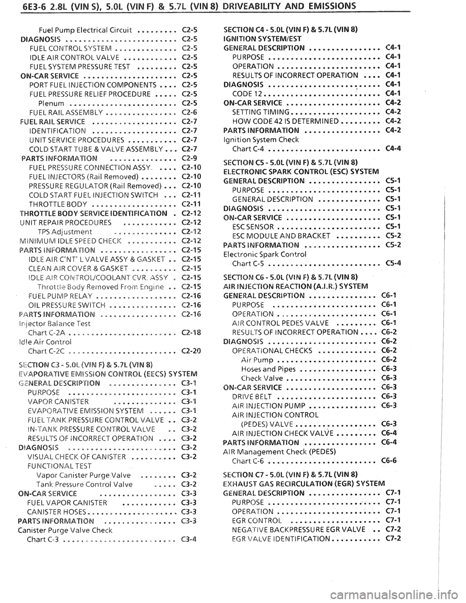
......... Fuel Pump Electrical Circuit C2-5
DIAGNOSiS ......................... CZ-5
.............. FUEL CONTROL SYSTERA C2.5
............ IDLE AIR CONTROLVALVE CZ-5
......... FUEL SYSTEM PRESSURE TEST C2-5
ON-CAR SERVICE ..................... C2-5
PORT FUEL INJECTION COMPONENTS .... Cf-5
FUEL PRESSURE RELIEF PROCEDURE ..... C2-5
Plenum ......................... C2-5
................ FUEL RAILASSEMBLY CP-6
FUEL RAIL SERVICE ................... C2-7
................... IDENTIFICATION C2-7
........... UNIT SERVICE PROCEDURES C2-7
COLD START .TUBE & VALVE ASSEMBLY ... ~2-7
PARTS INFORMATION ............... CZ-9
.... FUEL PRE5Si.J RE COPdNECl'ION ASSY C2-10
FUEL INJECTORS (Rail Removed) ........ C2-10
PRESSURE REGULATOR (Ball Removed) ... C2-10
COLD START FUEL INJEClION SWITCH ... C2-1%
THROTTLE BODY ................... CZ-11
VWROTTLE BODY SERVICE IDENTIFICATION . C2-12
............ UNIT REPAIR PROCEDURES Cf-112
TPS Adjcistment .............. C2-12
MiNIRilUM IDLE SPEED CHECK ........... CE-'I2
................. PARTS INFORMATION C2-15
IDLE AIR C'NT' L VALVE ASSY (3r: GASKET . . C2-15
CLEAN AIR COVER & GASKET .......... C2-15
SECTION C4 . 5.0h (VIN F) & 5.7L (VIN 8)
lGNITlON SYSTEMIEST
................ GENERAL DESCRIPTION C4-1
......................... PURPOSE C4-1
OPERATION ....................... C4-1
RESULTS OF INCORRECT OPERATION .... C4-1
......................... DIAGNOSIS C4-1
CODE 12 .......................... C4-1
ON-CAR SERVICE ..................... C4-2
SETTING TIMING .................... C4-2
HOW CODE 42 IS DETERMINED ......... C4-2
................. PARTS INFORMATION C4-2
lgn~tion System Check
Chart C-4
......................... C4-4
SECTION C5 . 5.0L (VIM F) & 5.7L JVIN 8)
ELECTRONIC SPARK CONTROL (ESC) SYSTEM
................ GENERAL DESCRIPTION C5-1
......................... PURPOSE C5-1
.............. GENERAL DESCRIPTION C5-1
......................... DlAGNOSiS C5-1
..................... ON-CAR SERVICE C5-1
....................... ESCSENSOR 65-1
.......... E4C MODULE AiYD BRACKET 165-2
................. PARTS INFORMATXBM C5-2
Electronic Spark Control
Chiirt C-5 ......................... C5-4
IDLE AIR CBi\~TROVCOOLANl'CVR . AS57 0
Throlrle Body Reinovecl Froti.1 Engine . .
FUEL PUlVlP RELAY ..................
................ OIL PRESSURE 5WETCI-I
P/%RVS INFORMATION .................
Irilector Halarlce Test
Chart
C-2A ........................
Idle Air Control
Chart
C-%C ........................
C2-I 5 SECYlOM Ct; . 5.0L (VlN F) & 5.7L (VIN 8)
62-1 5 A8W INJECTION REACTION (A.I.R.) SYSTEM
C2-16 GENERAL DESCRbPTION ............... CG-I
C2-16 PURPOSE ....................... C6-1
C2-76 OPE RATION ...................... C6-1
AIR COPJTROL PEDES VALVE ......... C6-I
C2-'18 RESULTS OF INCORRECT OPERATION .... C6-2
DIAGNOSIS ........................ C6-2
............. Cf -20 OPERATIONAL CHECKS C6-2
SbCTIBN C3 . 5.0L (VIN F) h 5.7L (V1N 8)
I:itAPORAIIVE EMISSlON CONTROL (EECS) SYSTEM
LZNERA. L DESCRIP'rION ............... C3-'!
PURPOSE ........................ C3-1
VAPOR CANISTER
.............. $3-1
EVAF'OFt/?ITIVE EMISSION SYSTEM .me.e. C3-4
FUEL TANK PRESSURE CONTROL VALVE . . C3-2
IN-'TANK PRESSURE CONTROL VALVE . . 63-2
RESULTS OF IRiCORRECT OPERATIGN .... C3-2
DIAGNOSIS ........................ C3-2
VISUAL CHECK OF CANIS'rkR .......... C3-2
FUNCPIONAL TEST
Vapor
Can~saer Purge Valve ........ C3-9
Tank Pressure Control Valve ..... C3-2
ON-CAR SERVICE ................. C3-3
FUEL VAPOR CANISTER ............ C3-3
CANISTER HOSES.
................... C3-3
PARTS INFORiblAT%BN ................ C3-3
Canister Purge Valve Check
Chart
C-3 ......................... C3-4
...................... Air Pump C6-2
................. Hoses and Pipes C6-3
.................... Check \/alve C6-3
.................... ON-CAR SERVICE C6-3
...................... DRIVE BELT C6-3
AIR INJECTION PUMP ............... C6-3
AIR INJECTION CONTROL
.................. (PEDES) VALVE C6-3
AIR ~NJECTION CIIECK VALVE ......... ~6-4
................ PARTS INFORMATION C6-4
AIR Management Check (PEDES)
........................ Chart C-6 C6-6
SECTlON C7 . 5.OL (VlN F) & 5.7L (VIN 8)
EXHAUST GAS RECIRCULATION {EGR) SYSTEM
GENERAL DESCRIPI'ION ..............*. C7-1
......................... PURPOSE C7-I
OPERATION
....................... C7-1
EGR
CONTROL .................... C7-1
NEGATIVE BACKPRESSURE EGR VALVE . . C7-2
EGR \/ALVE IDEhITIFICATION ........... C7-2
Page 655 of 1825
6E3-A-2 2.88, (VIM S) DRIVEABILITY AND EMISSIONS
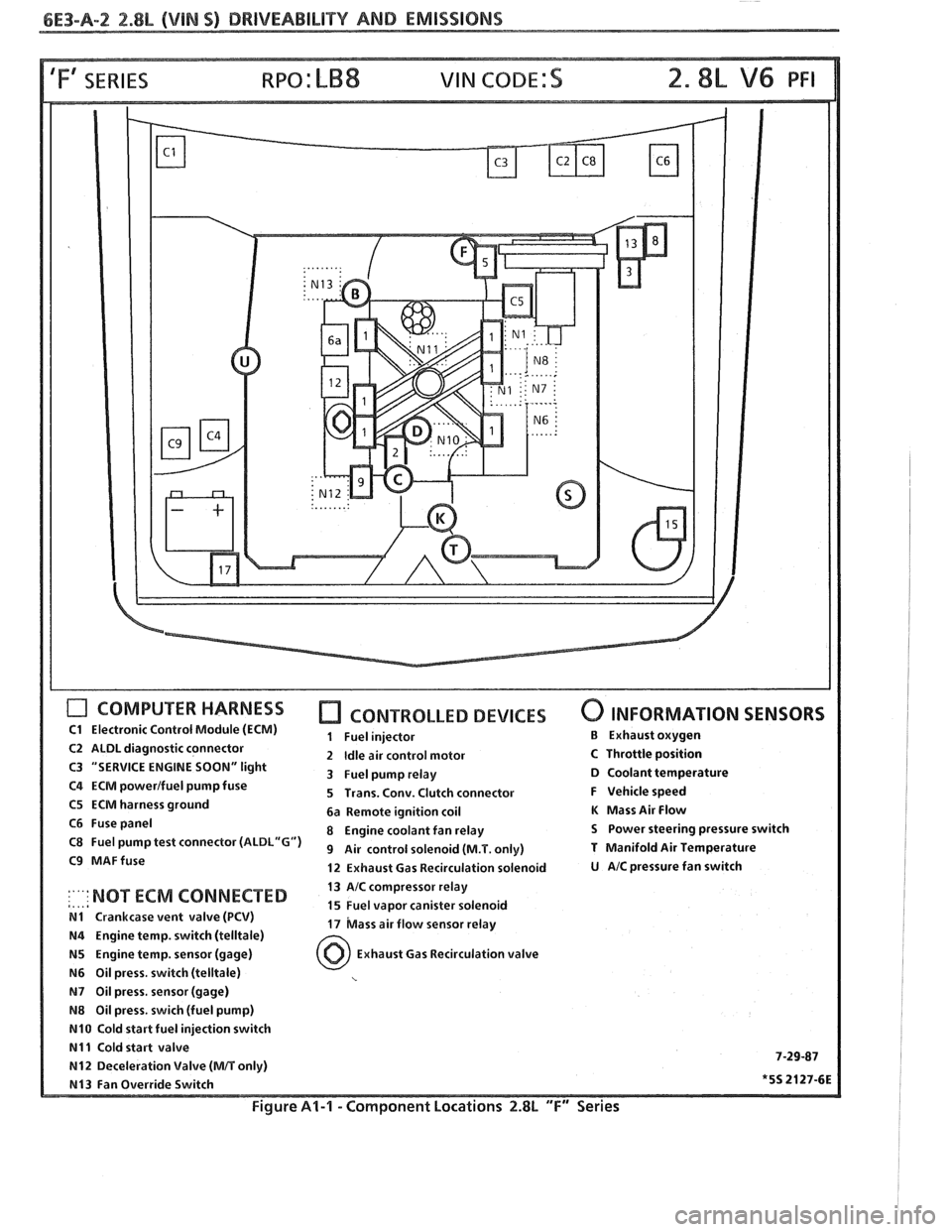
'Fa SERIES
COMPUTER HARNESS
C1 Electronic Control Module (ECM)
C2 ALDL diagnostic connector
C3 "SERVICE ENGINE
SOON" light
C4 ECM powerlfuel pump fuse
C5 ECM harness ground
C6 Fuse panel
C8 Fuel pump test connector
(ALDL"G")
C9 MAFfuse
CONTROLLED DEVICES
1 Fuel injector
2
Idle air control motor
3 Fuel pump relay
5 Trans. Conv. Clutch connector
6a Remote ignition coil
8 Engine coolant fan relay
9 Air control solenoid (M.T. only)
12 Exhaust Gas Recirculation solenoid
0 INFORMATION SENSORS
B Exhaust oxygen
C Throttle position D Coolant temperature
F Vehicle speed
K Mass Air Flow
S Power steering pressure switch
T Manifold Air Temperature
U AIC pressure fan switch
13 AIC compressor relay
,..,a :'"' NOT ECM 'ONNECTED 15 Fuel vapor canister solenoid N1 Crankcase vent valve (PCV) 17 bass air flow sensor relay N4 Engine temp. switch (telltale)
N5 Engine temp. sensor (gage) Exhaust Gas Recirculation valve
N6 Oil press. switch (telltale)
N7 Oil press, sensor (gage)
N8 Oil press. swich (fuel pump)
N10 Cold start fuel injection switch
N11 Cold start valve 7-29-87 N12 Deceleration Valve (MIT only)
N13 Fan Override Switch *5S 2127-6E
Figure Al-l - Component Locations 2.8L "F" Series
Page 657 of 1825
6E3-A-4 2.8L (VIN S) DRIVEABILITY AND EMISSIONS
ECMIIGN
I I
I
1
I
I
I I
I
PRIMARY COIL I
I
I
I
I
FUEL PUMP
CONNECTOR FUEL
FUEL PUMP SIGNAL