1988 PONTIAC FIERO oil
[x] Cancel search: oilPage 580 of 1825

DRIVEABILITY AND EMISSIONS - 5.OL (\/IN El 6EZ-CZ-5
sent to the ECM. The ECM then increases the injector
base pulse width, permitting increased fuel flow.
As the throttle valve rotates in response to
movement of the accelerator pedal, the throttle shaft
transfers this rotational movement to the
'I'PS. A
potentiometer (variable resistor) within the TPS
assembly changes its resistance (and voltage drop) in
proportion to throttle movement.
By applying a reference voltage (5.0 volts) to the
TPS input, a varying voltage (reflecting throttle
position) is available at the TPS output. For example,
approximately 2.5 volts results from a 50% throttle
valve opening (depending on TPS calibration). The
voltage output from the TPS assembly is routed to the
ECM for use in determining throttle position.
FUEL PUMP
The fuel pump is a turbine type, low pressure
electric pump, mounted in the fuel tank. Fuel
is
pumped at a positive pressure (above 62
kPa or 9 psi)
from the fuel pump through the in-line filter to the
pressure regulator in the TBI assembly Excess
fuel is
returned to the fuel tank through the fuel return line.
The fuel pump is attached to the fuel gage sender
assembly. A fuel strainer is attached to the fuel pump
inlet line and prevents dirt particles from entering the
fuel line and tends to separate
water from the fuel
Vapor lock problems are reduced when using an
electric
pump because the fuel is pushed from the tank
under pressure rather than being pulled
under
vacuum, a condition that produces vapor.
An inoperative fuel pump would cause
a. no start
condition. A fuel pump which does not provide enough
pressure can result in poor performance. (See "Fuel
System Pressure Test" procedure).
FUEL PUMP ELECTRICAL CIRCUIT
When the key is first turned "ON" without the
engine running, the ECM turns the
Fuel pump relay
"ON" for two seconds. This builds
up the fuel pressure
quickly. If the engine is not started within two
seconds, the
ECM shuts the fuel pump "OFF" and
waits until the engine starts. As soon as the engine is
cranked, the ECM turns the relay
"ON" and runs the
fuel pump.
As a backup system to the fuel pump relay, the
fuel pump can also be turned on
by the oil pressure
switch. The oil pressure sender has two circuits
internally. One operates the oil pressure indicator or
gage in the instrument cluster,
itnd the other is
anormally open switch which closes when oil pressure
reaches about 28
kPa (4 psi). If the fuel pump relay
fails, the oil pressure switch will run the fuel pump. An
inoperative fuel pump relay can result in long
cranking times, particularly if the engine is cold. The
oil pressure switch will turn on the fuel pump as soon
as oil pressure
reaches about 28 kPa (4 psi).
FUEL CONTROL
Always start with the "Diagnostic Circuit Check"
in Section
"6E2-A". This will reduce diagnosis time
and prevents unnecessary replacement of parts. The
information in this check will direct diagnosis
concerning "Engine
Crunlis But Won't Run" and the
"Fuel Control System," Section
"6E2-C2", including
diagnosis of an injector, pressure regulator,
fuel pump,
fuel
pump relay, and oil pressure switch.
Idle Air Control (IAC) Valve
A "Scan" tool reads IAC position in steps, calletl
"Counts." "0" steps indicates the ECM is commanding
the
IAC to be driven in, to a fully seiltetl position
(minimum idle air).
The higher the number steps, the
more idle air being allowed to pass
by the IAC valve.
cnose Refer to CHART C-2C for information to cliil,
the function of the IAC valve.
Driva bility
Refer to Section "B" for driveability symptoms
related to the fuel control.
ON-VEHICLE SERVICE
GENERAL SEWVICE INFORMATION
CAUTION:
e To prevent personal injury or damage to the
vehicle
as the result sf an accidental start,
disconnect and reconnect the negative
battery cable before and after service is
performed.
@ Also, catch any fuel that leaks out when
disconnecting the fuel lines, by covering the
fittings with
a shop cloth. Place the cloth in
an approved container when work is
complete.
The 'FBI unit repair procedures cover component
replacement with the unit on the vehicle,
tIowever,
throttle body replacement requires that the complete
unit
be removed from the enginc.
Page 588 of 1825
DRIVEABILITY AND EMISSIONS - S.0L (VIN E) 6EZ-C2-13
"THROTTLE BODY INJECTION (TBI) UNIT
Replacement (Figure C2-18)
a Remove or Disconnect
1. THERMAC hose from engine fitting.
2. Electrical connectors to IAC valve, TPS and fuel
injectors.
3. Grommet with wires from throttle body.
4. Throttle linkage, return
spring(s) transmission
control cable and cruise control (wherever
applicable).
5. Vacuum hoses (noting position of hoses) and
bracket.
6. Fuel inlet and return lines (use back-up wrench
J-29698-A or BT-8251-A). Discard o-
rings from
nuts.
7. TBI mounting hardware.
8. TBI flange (manifold mounting) gasket and
discard.
NOTICE: Stuff manifold opening with a rag to
prevent material from entering
engine, and remove old gasket
material from surface of intake
manifold.
Inspect
@ Intake manifold bore for loose parts and foreign
material, etc.
@ Intake manifold sealing surface for cleanliness.
Install or Connect
1. New TBI flange (manifold mounting) gasket.
2.
TI31 with mounting hardware.
Tighten
@ Hardwareto, 16.5N-m( 12Ib. ft.).
3. New o-rings on fuel line nuts
4. Fuel inlet and outlet lines.
Tighten - @ To 23 N.m (17 lb. ft.). (Use back-up wrench
J-29698-A or BT-8251-A to keep TBI nuts
from turning.)
5. Vacuum hoses and bracket.
6. Throttle linkage, return
spring(s) transmission
control cable and cruise control (wherever
applicable).
7. Grommet with wire harness to throttle body.
8. Electrical connectors, making sure connectors are
fully seated and latched.
9. Check to see if accelerator pedal is free by
depressing pedal to the floor
and releasing while
engine is "OFF".
10. With engine "OFF," and ignition "ON," check for
leaks around fuel line nuts.
11. Start engine and check for fuel leaks.
FUEL HOSEIPIPE ASSEMBLIES
Materials
Fuel Lines. These are welded steel tubes, meeting GM
Specification 124-M, or its equivalent. The fuel feed
line is
318" diameter, and the fuel return line is 5/16"
diameter. Do not use copper or aluminum tubing to
replace steel tubing. Those materials do not have
satisfactory durability to withstand normal vehicle
vibr, ii t' lon.
Clamps. These are stainless steel, screw band type
clamps,
#249472, or equivalent.
Coupled Hose. These are not to be repaired and are
replaced
&as an assembly.
Uncoupled Hose. Use only reinforced fuel resistant
hose, made of "fluroelastomer" material.
[lo not use w
hose within 4 inches (100 mm) of any part of the
exhaust system, or within 10 inches
(254 mm) of the
catalytic converter. The hose's inside diameter nus st
match the outside diameter of the steel tubing.
Fuel Line Repair
1. Cut
a piece of fuel hose 4 inches (100 mm) longer
than the section of line to be removed. If
more
than 6 inches (152 tnm) is to be removed, use a .
combination of steel pipe and hose. The
hose
length should not be more than 10 inches total.
2. Cut a section of pipe to be replacccl, with a tube
cutter. C'se the first step of a double flaring tool to
form a bead on the ends
of the pipe and also, on the
new section of pipe, if used.
3. Slide
the hose
clanlps onto the pip2 and push the
hose
2 inches (51 mm) onto each portion of the fuel
pipe. Tighten a
clamp on each side of the repair.
4. Secure
fuel line to the frame.
FUEL PUMP RELAY
(Figure
CZ-19)
The fuel pump relay is mounted in the engine
compartment. Other than checking for loose
connectors, the only service possible is replacement.
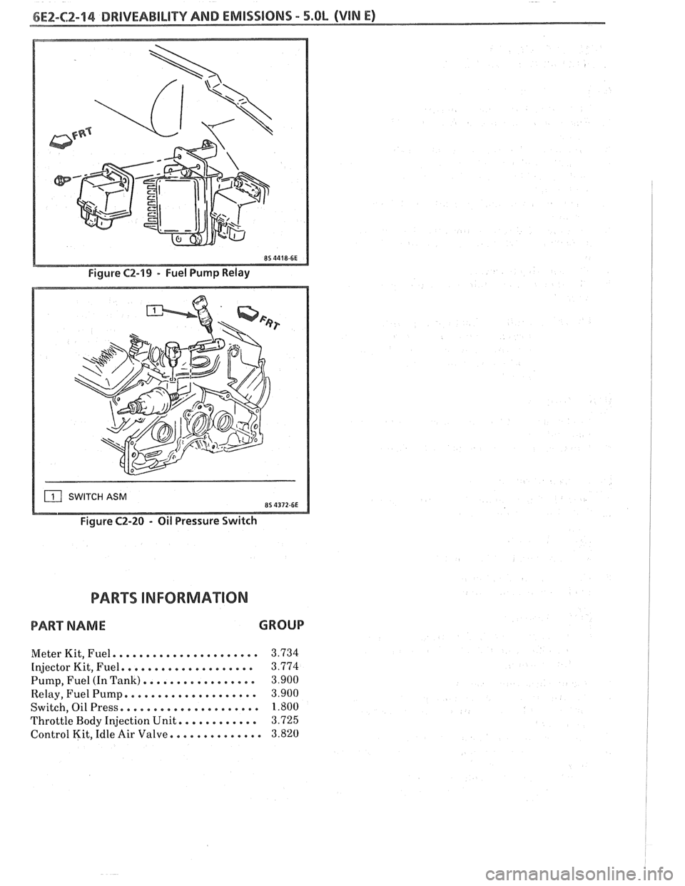
OIL PRESSURE SWITCH
(Figure C2-20)
The oil pressure switch is li~ounted on the engine.
This switch is a parallel power supply, with the fuel
pump relay, and will provide battery voltage to the
fuel
pump, after approximately 28 kPa (4 psi) oil
pressure is reached.
Page 589 of 1825
SWITCH ASM
Figure C2-20 - Oil Pressure Switch
PART D INFORMA"F0N
PART NAME GROUP
Meter Kit, Fuel. . . . . . . . . . . . . . . . . . . . . . 3.734
Injector Kit, Fuel. . . . . . , . . . . . . . . . . . . . 3.774
Pump, Fuel (In Tank). . . . . . . . . . . . . . . . . 3.900
Relay, Fuel Pump. . . . . . . . , . . . . . . . . . . . 3.900
Switch, Oil Press. . . . . . . . . . . . . . . . . . . . . 1.800
Throttle Body Injection Unit. . . . . . . . . . . . 3.725
Control Kit, Idle Air Valve. . . . . . . . . . . . . . 3.820
Page 600 of 1825
DRIVEABILITY AND EMISSIONS 5.QL (VIN E) 6Ef-C4-1
SECTION C4
IGNITION SYSTEM 1 (EST)
CQN"FEB\BTO
GENERAL DESCRIPTION ............... C4-1
PURPOSE ........................ C4-1
OPERATION
............*......... C4-1
DIAGNOSIS
........................ C4-1
..... RESULTS OF INCORRECT EST OPER. C4-1
HOW CODE 42 IS DETERMINED ....... C4-2
GENERAL DESCRIPTION
PURPOSE
The High Energy Ignition (HE11 system controls
fuel combustion by providing a spark to ignite the
compressed
aidfuel mixture at the correct time. To
provide improved engine performance, fuel economy,
and control of exhaust emissions, the ECM controls
distributor spark advance (timing) with the Electronic
Spark Timing (EST) system.
Only the Electronic Spark 'Timing (EST) system
will be described here. Additional information on the
HE1 system is found in Section 6D.
OPERATION
The standard high energy ignition (HEI) system
(described in Section 6D) has a modified distributor
module, which is used in connection with EST.
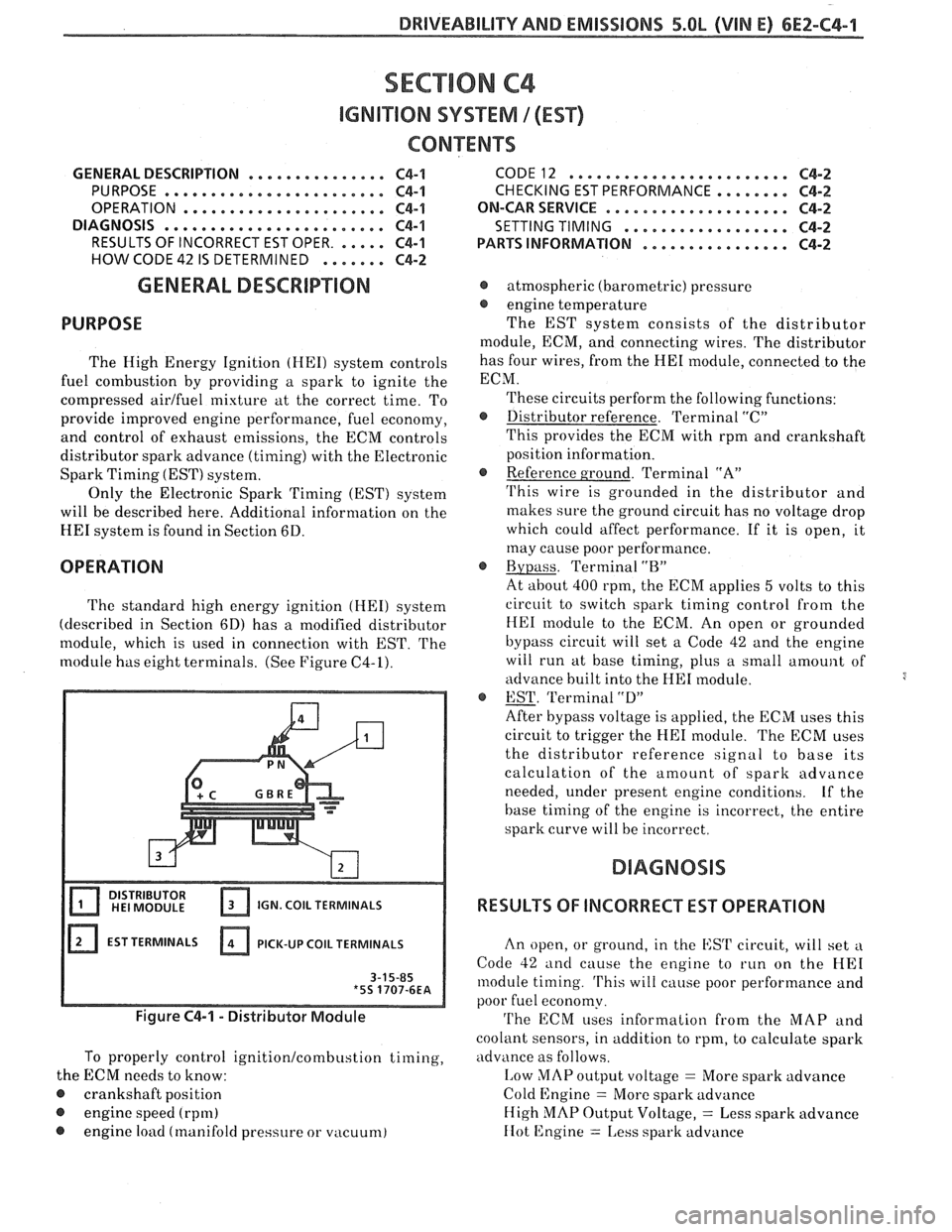
The
module has eight terminals. (See Figure C4-1).
IGN. COIL TERMINALS
EST TERMINALS PICK-UP
COIL TERMINALS
Figure C4-1 - Distributor Module
To properly control ignition/combustion timing,
the ECM needs to know:
@ crankshaft position
@ engine speed (rpm)
@ engine load (manifold pressure or vacuum)
CODE12 ........................ C4-2
CHECKING EST PERFORMANCE ........ C4-2
ON-CAR SERVICE ...a.e.............. C4-2
SETTING TIMING
.................. C4-2
PARTSINFORMATION ................ C4-2
@ atmospheric (barometric) pressure
@ engine temperature
The EST system consists of the distributor
module, ECM, and connecting wires. The distributor
has four wires, from the
HE1 module, connected to the
ECM.
These circuits perform the following functions:
@ Distributor reference. Terminal "C"
This provides the ECM with rpm and crankshaft
position information.
@ Reference ground. Terminal "A"
'I'his wire is grounded in the distributor and
makes sure the ground circuit has no voltage drop
which could affect performance. If it is open, it
may cause poor performance.
@ Bypass. Terminal "BJ'
At about 400 rpm, the ECM applies 5 volts to this
circuit to switch spark timing control
from the
HE1 module to the ECM. An open or grounded
bypass circuit will set a Code 42 and the engine
will run at base timing, plus a small
amount of
advance built into the
HE1 module.
@ EST. 'Terminal "D"
After bypass voltage is applied, the ECM uses this
circuit to trigger the
HE1 module. The ECM uses
the distributor reference signal to base its
calculation of the amount of spark advance
needed, under present engine conditions.
Lf the
base timing of the engine is incorrect, the entire
spark curve will be incorrect.
RESULTS OF INCORRECT EST OPERATION
An open, or ground, in the EST circuit, will set a
Code 42 and cause the engine to run on the HE1
module timing. 'I'his will cause poor performance and
poor fuel economy.
'I'he ECM uses information from the MAP and
coolant sensors, in addition to rpm, to calculate spark
advance as follows.
I,ow MAP output voltage = More spark advance
Cold Engine
= More spark advance
High
MAP Output Voltage, = Less spark advance
IIot 12ngine = 1,ess spark advance
Page 601 of 1825
6E2-C4-2 5.8L (VIN E) DRIVEABILIW AND EMISSIONS
Therefore, detonation could be caused by low MAP
output or high resistance in the coolant sensor circuit.
Poor performance could be caused by high MAP
o~~tput or low resistance in the coolant sensor circuit.
HOW CODE 42 IS DETERMINED
When the system is running on the HE1 module,
that is, no voltage on the bypass line, the
HE1 module
grounds the EST signal. The ECM expects to see no
voltage on the EST line during this condition. If it
sees a voltage, it sets Code
42 and will not go into the
EST mode. When the rpm for EST is reached (about
400 rpm),
the ECM applies 5 volts to the bypass line and the EST
should no longer be grounded in the
HE1 module, so,
the EST voltage should be varying.
If the bypass line is open, the
HE1 module will not
switch to EST mode, so, the EST voltage will be low
and Code
42 will be set.
If the EST line is grounded, the HE1 module will
switch to EST but, because the line is grounded, there
will be no EST signal and the engine will not run. A
Code
42 may, or may not, be set.
The description, operation, and diagnosis of the
HE1 system are found in Section 6D of this manual.
This section will address diagnosis of that portion of
the Ignition System pertaining to the EST operation.
CODE 12
Code 12 is used during the Diagnostic Circuit
Check procedure to test the code display ability of the
ECM. This code indicates that the ECM is not
receiving the engine rpm (REFERENCE) signal. This
occurs with the ignition key
"ON" and the engine not
running.
The "Reference" signal, also, triggers the fuel
injection system. Without the "Reference" signal, the
engine cannot run.
ON-CAR SERVICE
SETTING TIMING
Set timing according to instructions on Vehicle
Emission Control Information label.
PARTS INFORMATION
PART NAME GROUP
....................... Module, Distr 2.383
......................... Coil, Distr 2.170
Page 603 of 1825
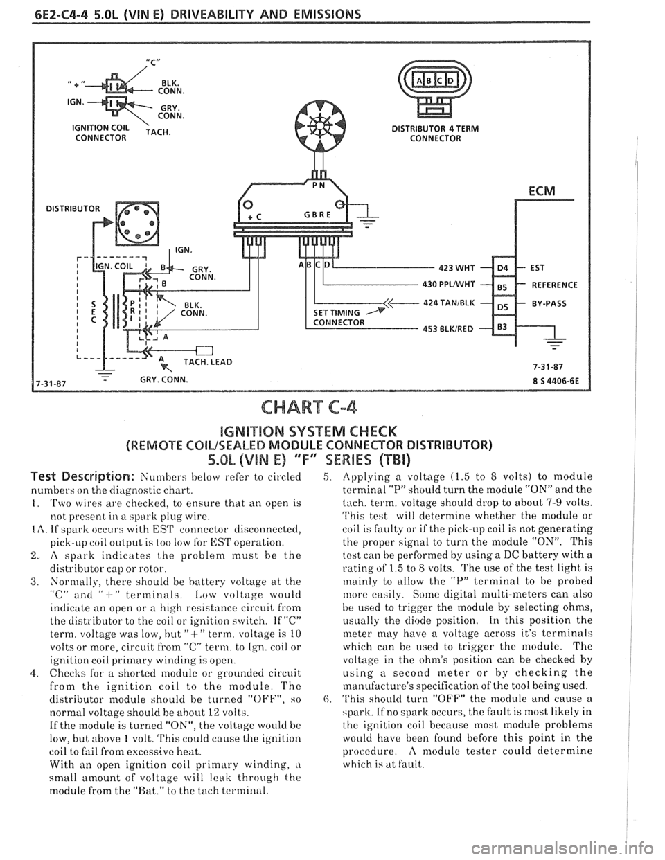
6E2-C4-4 5.OL (VIN E) DRIVEABILITY AND EMISSIONS
CONNECTOR
430 PPUWHf
424 TANIBLK
CHART C-4
IGMB"$IIQN SYSTEM CHECK
(REMOTE COILSEALED MODULE CONNECTOR DISTRIBUTOR)
5.OL (VIN E) 'TF"7SEWBES (TBi)
Test De~driptian: Siin~bers below refer to circled
numbers
on the diagilostic chart.
1. 'Two wires are checkecl, to ensure that ti11 open is
not present
in a spark plug wire.
IA. If spark occurs with EST connector disconnected,
pick-LIP coil
oiltp~it is too !OW for l,:SrI' operation.
2. A spark indicates t,he problem must be the
distributor cap or rotor.
3. Normally, there should be battery voltage at the "c" ailti " -I-" terminals. Low voltage would
indicate an open or
a high resistance circuit from
the distributor to the coil or ignition switch. If "C"
term. voltage was low, but
"+" term. voltage is 10
volts or more, circuit
from "C" term. to Ign. coil or
ignition coil
primary winding is open.
4. Checks for a shorted module or grounded circuit
from the ignition coil to the module.
'I'hc
distributor module should be turned "OFF", so
normal voltage should be
about 12 volts.
If the module is turned "ON", the voltage would be
low, but above
1 volt. This could cause the ignition
coil to fail from excessive heat.
With an open ignition coil primary winding,
a
small amount of voltage will leak throtrgh the
module from the "Bat." to the tach terminal.
5. Applying a voltage (1.5 to 8 volts) to module
terminal
"P" should turn the module "ON" and the
tach. term. voltage should drop to about 7-9 volts.
'I'his test will determine whether the module or
coil is faulty or if the pick-up coil is not generating
the proper signal to turn the module "ON". This
test can be performed by using a DC battery with a
rating of 1.5 to
8 volts. The use of the test light is
~nainly to tillow the "P" terminal to be probed
tilore easily. Some digital multi-meters can also
be used to trigger the
module by selecting ohms,
i~sually the diode position. 111 this position the
meter may have a voltage across it's terminals
which can be
used to trigger the module. The
voltage in the ohm's position can be checked
by
using a second meter or by checking the
manufacture's specification of the tool being used.
6. 'I'his should turn "OFF" the module and cause a
spark. If no spark occurs, the fault is most likely in
the ignition coil because
most module problems
would have been found before this point in the
procedure.
A modulc tester could determine
which is at fault.
Page 614 of 1825

DRIVEABILITY AND EMISSIONS 5.OL (VIN E) 6EZ-C6-3
CAUTION: Do Not Oil A.I.R. Pump
Hoses and Pipes
inspect
1. Hose or pipe for deterioration or holes.
2. All hoses or pipe connections, and clamp tightness.
3. Hose or pipe routing. Interference may cause
wear.
4. If a leak is suspected on the pressure side of the
system or if a hose or pipe has been disconnected
on the pressure side, the connections should be
checked for leaks with a soapy water solution.
With the pump running, bubbles will form if a
leak exists.
Check Valve
a inspect
1. A check valve should be inspected whenever the
hose is disconnected form a check valve or
whenever check valve failure is suspected.
(A
pump that had become inoperative and had shown
indications of having exhaust gases in the pump
would indicate check valve failure).
2. Blow through the check valve (toward the cylinder
head) then attempt to suck back through the check
valve Flow should only be in one
direction(toward the exhaust manifold). Replace
valve which does not operate properly.
ON-CAR SERVICE
DRIVE BELT
Remove or Disconnect
1. Inspect drive belt for wear, cracks or deterioration
and replace if required. When installing new belt,
it must be seated and fully secured in grooves of
all belt driven components.
AIR INJECTION PUMP
Remove or Disconnect
1. Hold pump pulley from turning by compressing
drive belt, then loosen pump pulley bolts.
2. Drive belt and pulley.
3. Hoses, vacuum, and electrical connections from
Air Injection Control valve.
4. Air pump mounting bolts, and pump assembly
(See Figure
C6-3).
Install or Connect
1. Air pump assembly, and tighten mounting bolts.
2. Spacer and pump pulley against centrifugal filter
fan.
3. Pump pulley bolts and tighten equally to 13 N m
(10 lb, ft).
4. Check
air injection system for proper operation
(see Chart C-6).
Figure C6-3 - Air Pump Service
AIR INJECTION CONTROL (PEDES) VALVE
Remove or Disconnect
1. Battery ground cable.
2. Adapter bolts (See Figure C6-4).
3. Air outlet hoses from valve.
4. Splash guard / cover
5. Electrical connectors and vacuum hoses from
valve.
6. Control valve.
Install or Connect
1. Control valve.
2. Electrical connectors.
3. Splash guard /cover
4. Air hoses to valve.
5. Battery ground cable.
6. Check
system operation (see
CHART C-6).
Page 629 of 1825

6EZ-C8-4 DRIVEABILITY AND EMISSIONS - 5.OL (VIN E)
I5 WAY (FRONT VIEW)
SPEED INPUT
4rH GEAR SIGNAL
422 TANIBLK
ALDL CONNECTOR
CHART C-8A
TRANSMISSION CONVERTER CLUTCH (TCC)
ELECTRICAL DIAGNOSIS
(Page 1 of 2)
5.OL (VIN E) "F" "SERIES (TBI)
Circuit Description:
The purpose of the automatic transmission torque converter clutch is to eliminate the power loss of the
torque converter, when the vehicle is in a cruise condition. This allows the convenience of the automatic
transmission and the fuel economy of a manual transmission.
Fused battery ignition is supplied to the TCC solenoid through the brake switch. the ECM will engage
TCC
by grounding CKT 422 to energize the solenoid.
TCC will engage when:
- Vehicle speed above 24 mph - Engine at normal operating temperature (above 70°C, 156°F)
- Throttle position sensor output not changing, indicating a steady road speed
- Brake switch closed
Test Description: Numbers below refer to circled solenoids
and relays before installing a
numbers on the diagnostic chart. replacement ECM. Replace
any solenoid or relay
1. Confirms 12 volt supply as well as continuity of that
measures less than 20 ohms.
TCC circuit.
2. Grounding the diagnostic terminal with engine Diagnostic Aids:
"OFF", should energize the capability of the ECM An
engine coolant thermostat that is stuck open or
to control the solenoid. opens
at too low a temperature, may result in an
3. Solenoid coil resistance must measure more than inoperative TCC.
20 ohms. Less resistance will cause early failure
of the ECM
drive^.". Using an ohmmeter, check
the solenoid coil resistance of
all ECM controlled