1988 PONTIAC FIERO brake
[x] Cancel search: brakePage 1485 of 1825
EXTERIOR LIGHTS WITH LAMP MONITOR
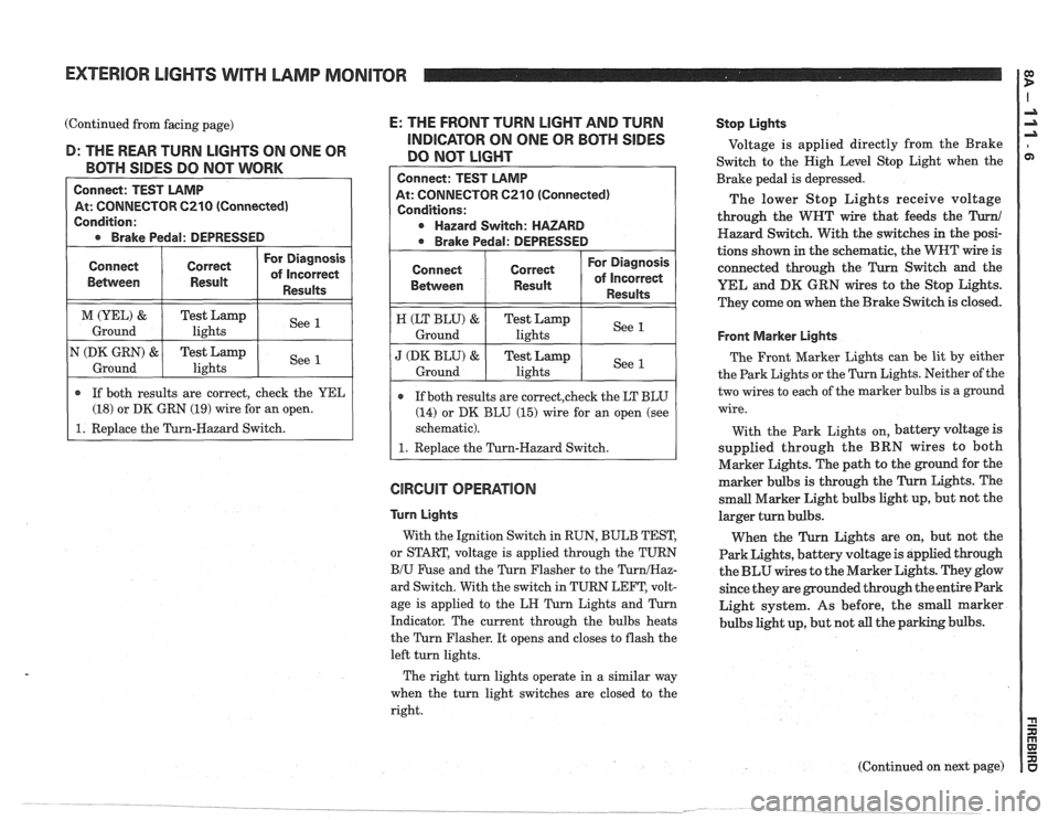
(Continued from facing page) E: THE FRONT TURN LIGHT AND TURN -- - INDICATOR ON ONE OR BOTH SIDES D: THE REAR TURN LIGHTS ON ONE OR
DO NOT LIGHT BOTH SIDES DO NOT WORK
Connect: TEST LAMP
At: CONNECTOR C210 (Connected)
Condition:
* Brake Pedal: DEPRESSED
GlRGUlT OPERATION
Connect
Bemeen
M (YEL) &
Ground
N
(DK GRN) &
Ground
Connect: TEST LAMP
At: CONNECTOR
6210 (Connected)
Conditions:
Hazard Switch: HAZARD
* Brake Pedal: DEPRESSED
Turn Lights
With the Ignition Switch in RUN, BULB TEST,
or START, voltage is applied through the TURN
B/U Fuse and the Turn Flasher to the TurnIHaz-
ard Switch. With the switch in TURN LEFT, volt-
age is applied to the
LH Turn Lights and Turn
Indicator. The current through the bulbs heats
the Turn Flasher. It opens and closes to flash the
left turn lights.
Connect
Between
H (LT BLU) &
Ground
J (DK BLU) &
Ground
Stop Lights
Voltage is applied directly from the Brake
Switch to the High Level Stop Light when the
Brake pedal is depressed.
The lower Stop Lights receive voltage
through the WHT wire that feeds the
Turn1
Hazard Switch. With the switches in the posi-
tions shown in the schematic, the WNT wire is
connected through the
Turn Switch and the
YEL and
DK GRN wires to the Stop Lights.
They come on when the Brake Switch is closed.
r If both results are correct, check the YEL
(18) or DK GRN (19) wire for an open.
1. Replace the Turn-Hazard Switch.
Correct
Result
Test Lamp lights
Test Lamp
lights
Front Marker Lights
The Front Marker Lights can be lit by either
the Park Lights or the Turn Lights. Neither of the
two wires to each of the marker bulbs is a ground
wire.
For Diagnosis
of Incorrect
Results
See 1
See 1
If both results are correct,check the LT BLU
(14) or DK BLU (15) wire for an open (see
schematic).
1. Replace the Turn-Hazard Switch.
Correct
Result
Test Lamp lights
Test
Lamp
lights
With the Park Lights on, battery voltage is
supplied through the BRN wires to both
Marker Lights. The path to the ground for the
marker bulbs is through the Turn Lights. The
small Marker Light bulbs light up, but not the
larger turn bulbs.
When the Turn Lights are on, but not the
Park Lights, battery voltage is applied through
the BLU wires to the Marker Lights. They glow
since they are grounded through the entire Park
Light system. As before, the small marker
bulbs light up, but not all the parking bulbs.
For Diagnosis
of Incorrect
Results
See 1
See 1
The right turn lights operate in a similar way
when the turn light switches are closed to the
right.
(Continued on next page)
Page 1489 of 1825
BACK UP LIGHTS
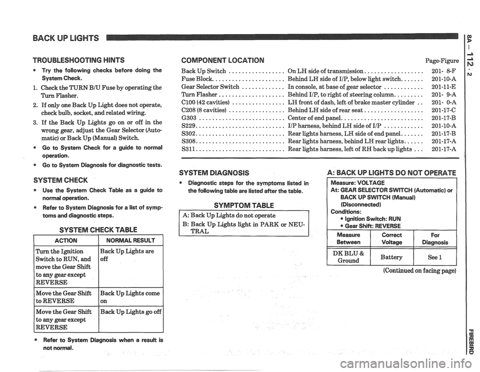
TROlJBLESHQOTlNG HINTS COMPONENT LOCATION Page-Figure
Try the following checks before doing the Back Up Switch ................. On LN side of transmission. ................. 201- 8-F
System Check. Fuse Block. ..................... Behind LH side of IIP, below light switch. ...... 201-10-A
............. ............ 1. Check the TURN BIU Fuse by operating the Gear
Selector Switch In
console, at base of gear selector
201-11-E
.................... Flasher. Flasher Behind IIP, to right of steering column. ........ 201- 9-A
2. If only one Back Up Light does not operate,
check bulb, socket,
and related
3. If the Back Up Lights go on or off in the
mong gear, adjust the Gear Selector (Auto-
matic) or Back Up (Manual) Switch.
el00 (42 cavities) ................ LR front of dash, left of brake master cylinder ..
C208 (8 cavities) ................. Behind LH side of rear seat. .................
6303 .......................... Center of end panel. ........................
S229. .......................... IIP harness, behind LH side of IIP ............
S302. .......................... Rear lights harness, LH side of end panel. ......
S308. .......................... Rear lights harness, behind LH rear lights. ..... - - Go to System Check for a guide to normal S3 11. .......................... Rear lights harness, left of RN back up lights
201-17-A ...
operation.
Go to System Diagnosis for diagnostic tests.
SYSTEM DlAGRlOSlS A: BACK UP LlGHTS DO NOT OPERATE
SYSTEM CHECK
Diagnostic steps for the symptoms listed in
Use the System Check Table as a guide to
the following table are listed
aMer the table. WlTCH (Automatic) or
normal operation. BACK
UP SWITCH
(Manual)
Refer to System Diagnosis for
a list of symp-
toms and diagnostic steps.
SYSTEM CHECK TABLE
the Ignition
Switch to RUN, and
move the Gear Shift
to
any gear except
REVERSE
Move the Gear Shift Back Up Lights come
to REVERSE 1 on - -
Move the Gear Shift Back
Up Lights go off
to any gear except
REVERSE
Refer to System Diagnosis when a result is
SYMPTOM TABLE
A: Back Up Lights do not operate
B: Back Up Lights light in PARK or NEU-
TRAL
(Continued on facing page)
not normal. Between
I Voltage I Diagnosis
I DKBLU& I Battery I See l I Ground
Page 1512 of 1825
THEFT DETERRENT SYSTEM: PASSKEY I a
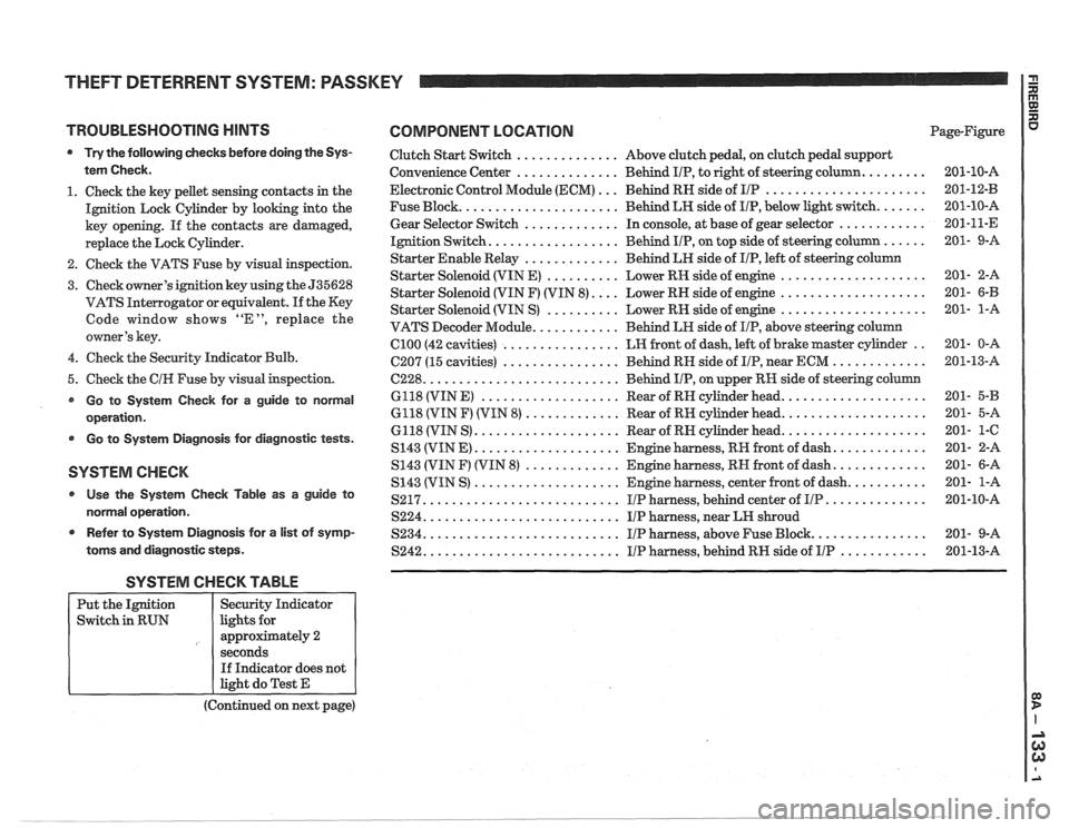
TROUBLESHOOTING HINTS COMPONENT LOCATION
Try the following checks before doing the Sys-
tem Check.
1. Check the key pellet sensing contacts in the
Ignition Lock Cylinder by looking into the
key opening. If the contacts are damaged,
replace the Lock Cylinder.
2. Check the VATS Fuse by visual inspection.
3. Check owner's ignition key using the 535628
VATS Interrogator or equivalent.
If the Key
Code window shows "E", replace the
owner's key.
4. Check the Security Indicator Bulb.
5. Check the
CIH Fuse by visual inspection.
Go to System Check for a guide to normal
operation.
Go to System Diagnosis for diagnostic tests.
SYSTEM CHECK
Use the System Check Table as a guide to
normal operation.
r Refer to System Diagnosis for a list of symp-
toms and diagnostic steps.
Clutch Start Switch .............. Above clutch pedal, on clutch pedal support
Convenience Center
.............. Behind IIP, to right of steering column. ........
Electronic Control Module (ECM) ... Behind RN side of IIP ......................
Fuse Block. ..................... Behind LH side of IIP, below light switch. ......
Gear Selector Switch ............. In console, at base of gear selector ............
Ignition Switch. ................. Behind IIP, on top side of steering column ......
Starter Enable Relay ............. Behind LH side of IIP, left of steering column
Starter Solenoid (VIN E)
.......... Lower RH side of engine ....................
Starter Solenoid (VIN F) (VIN 8). ... Lower RH side of engine ....................
Starter Solenoid (VIN S) .......... Lower RN side of engine ....................
VATS Decoder Module. ........... Behind LH side of IIP, above steering column
Cl00 (42 cavities) ................ LH front of dash, left of brake master cylinder ..
C207 (15 cavities) ................ Behind RN side of IIP, near ECM .............
6228. .......................... Behind IIP, on upper RH side of steering column
6118 (VIN
E) ................... Rear of RN cylinder head. ...................
6118 (VIN F) (VIN 8) ............. Rear of RH cylinder head. ...................
6118 (VIN S) .................... Rear of RN cylinder head. ...................
S143 (VIN E) .................... Engine harness, RR front of dash. ............
S143 (VIN F) (VIN 8) ............. Engine harness, RN front of dash. ............
S143 (VIN S) .................... Engine harness, center front of dash. ..........
S217. .......................... IIP harness, behind center of IIP. .............
S224. .......................... IIP harness, near LH shroud
S234. .......................... I/P harness, above Fuse Block. ...............
S242. .......................... IIP harness, behind RH side of IIP ............
SYSTEM CHECK TABLE
(Continued on next page)
Put
the Ignition
Switch in RUN
R aJ XI
Page-Figure u
Security Indicator
lights for
approximately 2
seconds If Indicator does not
light do Test E
Page 1519 of 1825
a HATCH RELEASE
RELEASE
RELAY
BRAKE
WARNING SYSTEM
I
CLOSED WITH PARKING - BRAKE APPLIED -
Page 1520 of 1825
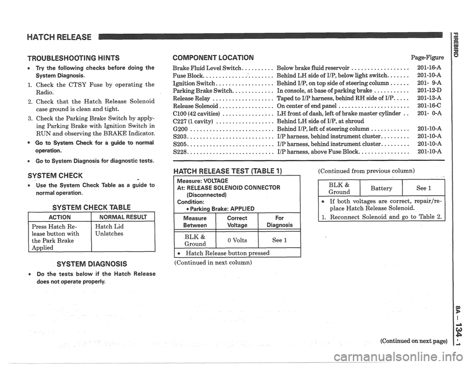
HATCH RELEASE P
E
TROUBLESHOOTING H lNTS
0 Try the following checks before doing the
System Diagnosis.
1. Check the CTSY Fuse by operating the
Radio.
2. Check that the Hatch Release Solenoid
case ground is clean and tight.
3. Check the Parking Brake Switch by apply-
ing Parking Brake with Ignition Switch in
RUN and observing the BRAKE Indicator.
@ Go to System Check for a guide to normal
operation.
Go to System Diagnosis for diagnostic tests.
SYSTEM CHECK -
o Use the System Check fable as a guide to
normal operation.
SYSTEM CHECK TABLE
lease button with
SYSTEM DIAGNOSIS
e Do the tests below if the Hatch Release
does not operate properly.
COMPONENT LOCATION Page-Figure
Brake Fluid Level Switch. ......... Below brake fluid reservoir ..................
Fuse Block. ..................... Behind LN side of IIP, below light switch. ......
Ignition Switch. ................. Behind IIP, on top side of steering column ......
Parking Brake Switch. ............ In console, at base of parking brake ...........
Release Relay ................... Taped to IIP harness, behind RN side of IIP. ....
Release Solenoid ................. On center of end panel ......................
el00 (42 cavities) ................ LN front of dash, left of brake master cylinder ..
C227 (1 cavity) .................. Behind LN side of IIP, at shroud
6200
.......................... Behind IIP, left of steering c
S203. .......................... IIP harness, behind instrunnent cluster. ........
.......................... ........ S205. IIP harness, behind instrument cluster.
S228. .......................... IIP harness, above Fuse Block. ...............
WATGH RELEASE TEST (TABLE 1)
At: RELEASE SOLENOID CONNECTOR
(Disconnected)
I 0 Parkina Brake: APPLIED I
I Measure I Correct I For
(Continued from previous column)
BLK & 1 o volts I See I 1 Ground
I r Hatch Release button pressed I --
(Continued in next column)
(Continued on next page)
Page 1521 of 1825
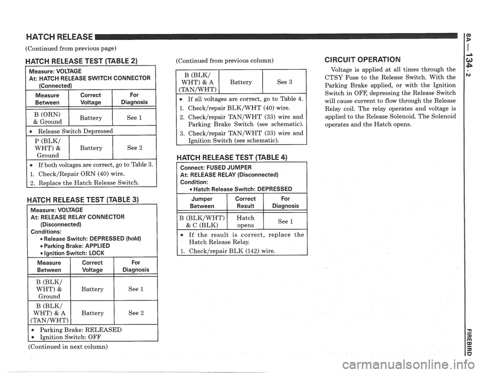
HATCH RELEASE 1:
(Continued from previous page) I
MATGH RELEASE TEST (TABLE 2)
Measure: VOLTAGE
At: HATCH RELEASE
SVVITCH CONNECTOR
[Connected)
-re I Correct I or I
Between I Voltage I Diagnosis I I
1 -a Release Switch De~ressed I
(ORN)
& Ground
HAKH RELEASE TEST (TABLE 3)
Measure: VOLTAGE
At: RELEASE RELAY CONNECTOR
(Disconnected)
Conditions:
0 Release Switch: DEPRESSED (hold)
r Parking Brake: APPLIED
a lanition Switch: LOCK
Battery (Continued from
previous column)
See 1
1. Checklrepair BLK/WHT (40) wire.
2. Checklrepair TAN/WHT (33) wire and
Parking Brake Switch (see schematic).
HATGH RELEASE TEST (TABLE 4)
Connect: FUSED JUMPER
At: RELEASE RELAY (Disconnected)
Condition:
a Hatch Release Switch: DEPRESSED
Jumper Correct For
Between Result Diagnosis
B (BLKIWHT) Hatch
& C (BLK) See 1 opens
e If
the result is correct, replace the
Hatch Release Relay.
1. Checklrepair BLK (142) wire.
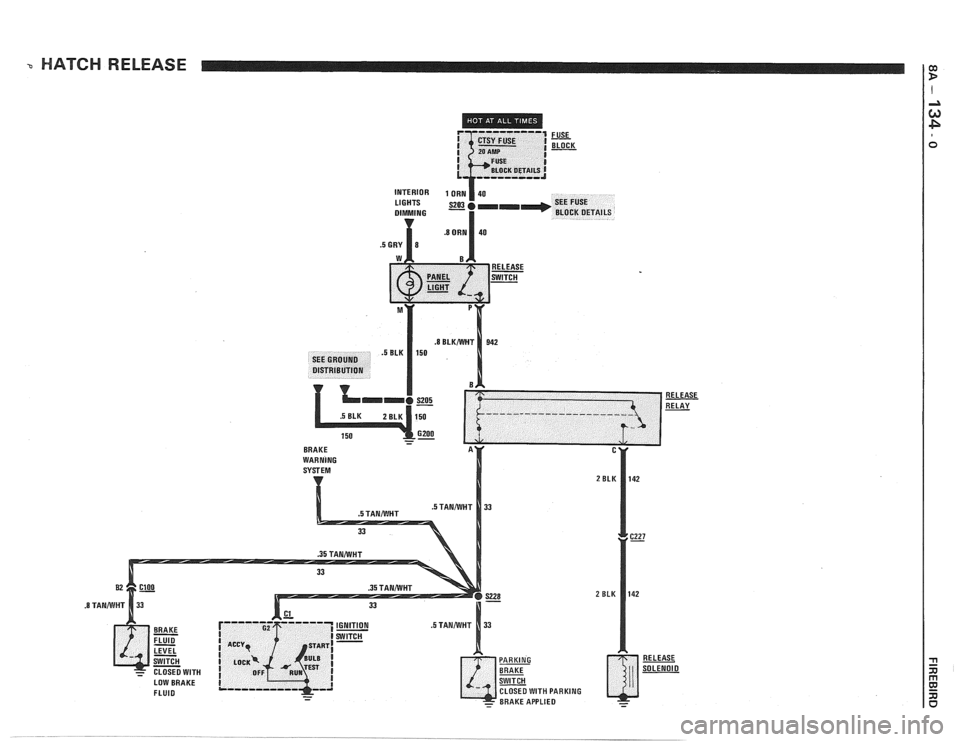
CIRCUIT OPERATION
Voltage is applied at all times through the
CTSY Fuse to the Release Switch. With the
Parking Brake applied, or with, the Ignition
Switch in
OFF, depressing the Release Switch
will cause current to flow through the Release
Relay coil. The relay operates and voltage is
applied to the Release Solenoid. The Solenoid
operates and the Hatch opens.
(Continued in next column)
Page 1530 of 1825
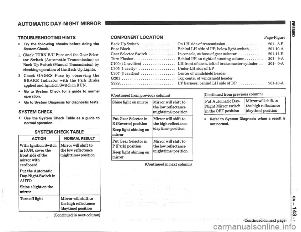
AUTOMATIC DAY-NIGHT MIRROR
TROUBLESHOOTING MINTS
Try the following checks before doing the
System
Gheck.
1. Check TURN BIU Fuse and the Gear Selec-
tor Switch (Automatic Transmission) or
Back
Up Switch (Manual 'L'ransfission) by
checking operation of the Back Up Lights.
2. Check GAGES Fuse by observing the
BRAKE Indicator with the Park Brake
applied and
IMtion Switch in RUN.
@ Go to System Gheck for a guide to normal
operation.
Go to System Diagnosis for diagnostic tests.
Use the System Check Table as a guide to
normal operation.
SYSTEM CHECK TABLE
nighttime) position
t the Automatic
ay-Night Switch
in
Shine a light on the
COMPONENT LOCATION Page-Figure
.................. Back Up Switch ................. On LN side of transIlnission 201- 8-F
...... Fuse Block. ..................... Behind LN side of IIP, below light switch. 201-10-A
............ Gear
Selector Switch ............. In console, at base of gear selector 201-11-E
........ 'Turn Flasher .................... Behind
PIP, to right of steering column. 201-
9-A
.. C100 (42 cavities) ................ LR front of dash, left of brake master cylinder 201-
0-A
6305 (1 cavity) .................. Under LH side of IIP
C307 (3 cavities) ................. Center of windshield header
6201
.......................... Top center of windshield header
............ S229. .......................... IIP harness, behind LW side of IIP 201-10-A
(Continued from previous column)
(Continued in next co (Continued
from previous column)
Refer to System Diagnosis when a result is
not normal.
(Continued in next colum)
(Continued on next page)
Page 1573 of 1825
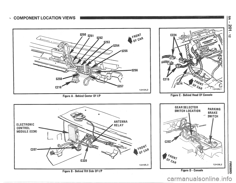
COMPONENT LOCATION VIEWS 1
Figure A - Behind Center Of IIP
EkEGTRONlC
CONTRhl h
MODULE (ECWIS)
Figure B - Behind RN Side Of IIP
SWITCH LBGATION BRAKE
Figure D - Console