1988 PONTIAC FIERO brake
[x] Cancel search: brakePage 1577 of 1825
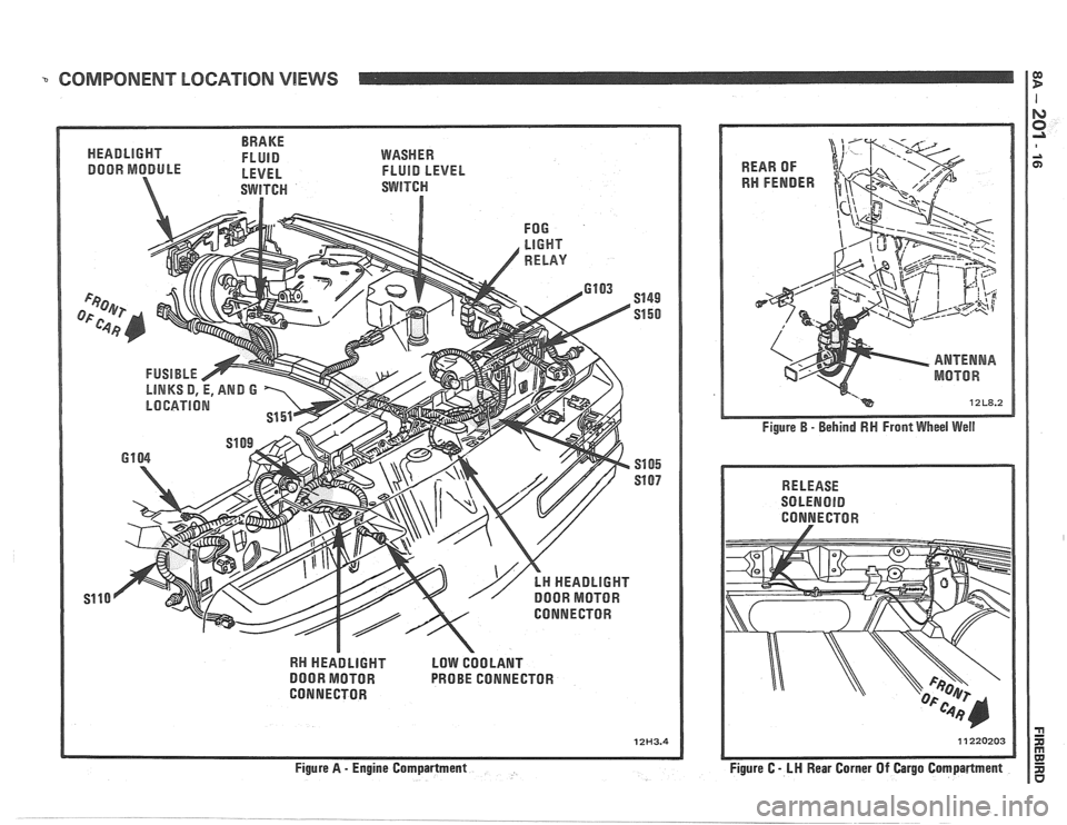
COMPONENT LOCATION VlEWS I E!
BRAKE
HEADLIGHT FLUID
DOOR MODULE - LEVEL
WASHER
FLUID LEVEL
RN HEADLIGHT LOW COOLANT
DOOR MOTOR PROBE CONNECTOR
CONNECTOR
12H3.4
Figure B - Behind RN Front Wheel Well
RELEASE
SOLENOlD
CONNECTOR
Figure C
- LH Rear Corner Of Cargo Compartment
Page 1587 of 1825
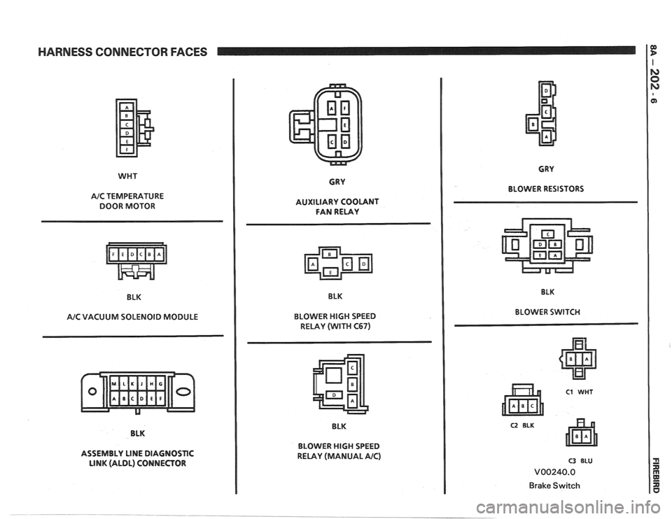
HARNESS CONNECTOR FACES
WHT
A/C TEMPERATURE
DOOR MOTOR
BLK
AIC VACUUM SOLENOID MODULE
BLK
ASSEMBLY
LINE DIAGNOSTIC
LINK (ALDL) CONNECTOR GRY
AUXILIARY COOLANT
FAN RELAY
BLK
BLOWER
HlGH SPEED
RELAY (WITH
C67)
BLK
BLOWER
HlGH SPEED
RELAY (MANUAL AIC)
CRY
BLOWER RESISTORS
BLK
BLOWER SWITCH
C2 BLK
C3 BLU
V00240.0
Brake Switch
Page 1600 of 1825
LIGHTING SYSTEMS AND HORNS 8B-I
SECTION 8B
NG SYSTEMS AND HORNS
CONTENTS
........................... GENERAL DESCRIPTION 8B-1
Exterior Lights
....................... ................... Back-up Lights .. 8B- 1
Center High-Mounted Stoplight .................... 8B-1
Exterior Light Monitor .................................. 8B-1
............................ .................... Fog Lights .. 8B-1
Front Parking/Turn Signal Lights ................ 8B-2
............................... Hazard Flashers .. ........ 8B-2 .................................................... Headlights 8B-2
License Plate Lights ..................................... 8B-2
Light Switch ............................................... 8B-2
............... Rear Tail/Stop/Turn Signal Lights 8B-2
Sidemarker Lights ........................................ 8B-2
Turn Signals .......................................... 8B-2
......................... Underhood Light ... ........ 8B-2
Horns .......................................................... 8B-3
....................................... ON-CAR SERVICE 8B-3
Exterior Lights
............................................. Back-up Lights 8B-3
Center High-Mounted Stoplight .................... 8B-3
Fog Lights .................................................... 8B-4
Front Parking/Turn Signal Lights ................ 8B-4
Hazard Flasher .............................................. 8B-5
....................................................... Headlights 8B-5
License Plate Lights ..................................... 8B-7
............... Rear Tail/Stop/Turn Signal Lights 8B-8
.......................................... Sidemarker Lights 8B-8
................... ............... Turn Signal Flasher .. 8B-9
......................................... Underhood Light 8B-9
Horns ................................................................. 8B-9
REPLACEMENT BULB
.................................... SPECIFICATIONS 8B- 10
The following information, previously shown in this section,
has been moved to the sections shown.
Back-up Lights Switch
............................. ... ............................................................................ 7
................................................................................................................................. Fuse Block 8A
Ignition Switch ........................................................................................................................... 3B
Interior Lights
................................................................................................................... 8A, 8C
Neutral Start Switch ..................................................................................................................... 7
Parking Brake Warning Switch
......................... ... .................................................................... 5
........................................................................ Seat Belt, Key and Headlight Warning Alarm 8A
Stoplight Switch .......................... .. ............................................................................................... 5
Windshield
Wipers/Washers .................................................................................................... 8E
GENERAL DESCRIPTION
The exterior lighting system includes the
headlights (and headlight motors to raise or lower the
headlights), front
parkinghurn signal lights, front
cornering lights, fog lights, rear
tail/stop/turn signal
lights, back-up lights, license plate lights, center
high-mounted stoplight, and the underhood light; it
also includes all associated wiring, controls and related
hardware for these lights.
BACK-UP LIGHTS - The back-up lights are
next to the rear license plate. They will come on when
the transmission is shifted to Reverse. On cars with an
automatic transmission, the back-up lights are
activated by the neutral start switch. On cars with a
manual transmission, they are activated by a separate
back-up light switch on the transmission. For more
information, see Section 7.
CENTER HIGH-MOUNTED STOPLIGHT-
The center high-mounted stoplight, in the center of the
rear spoiler, will come on whenever the brake pedal is
pushed down. The light is powered separately from the rear
tail/stop/turn signal
lights through a separate
circuit in the stoplight switch (see Section
8A).
EXTERIOR LIGHT MONITOR - The Driver
Information Center, on cars so equipped, also monitors
certain front and rear lights. When a bulb burns out,
the message
"FRONT LAMP" or "REAR LAMP"
will appear in the DIC display, and a light will come
on to indicate which bulb has burned out. For more
information, see Section
8A.
FOG LIGHTS -The fog light switches are to the
left of the steering column on the edge of the
instrument panel. To use the fog lights, first turn on the
headlights or parking lights. Then, push the middle
switch (with the fog light symbol) to turn on the fog
lights. Push the left
("OFF") switch to turn off the fog
lights.
The fog lights should not be used as a substitute
for the headlights.
Switching to high-beam headlights will turn off
the fog lights; switching back to low-beams will turn
the fog lights on again.
Page 1601 of 1825
88-2 LIGHTING SYSTEMS AND HORNS
The fog lights must be aimed for proper
illumination of the road. Fog light
aim should be
checked: at least once a year; when a new light housing
is installed; or if service or repairs in the front end area
have (or may have) disturbed the fog light mountings.
FRONT PARKING/TURM SIGNAL
LIGHTS - Pushing either side of the instrument panel
switch will turn on the front parking lights. (Pushing
the left side of the switch will also turn on the
headlights.) When the ignition is on and the turn signal
lever is moved, the appropriate front parking light
flashes to signal a turn. Both lights will flash when the
hazard flashers are on.
If the driver's door is opened when the parking
lights are on, a warning tone will sound. For more
information, see Section
8A-77.
HAZARD FLASHERS - The hazard warning
flasher is part of the turn signal circuit. Pushing in the
button (on the right side of the steering column) will
cause the front and rear turn signal lights, and the front
sidemarker lights, to flash. Pull out the collar around
the button to turn off the hazard flashers.
The hazard flashers will work with the ignition
either off or on. When the hazard flashers are on, the
turn signals do not
work.
The hazard flashers will stop flashing and stay on
brightly if the brake pedal is pushed down.
HEADLIGHTS - The headlights are controlled
by the switch on the instrument panel (to the left of the
speedometer). They will come on whether or not the
ignition is turned on. Pushing the upper left side of the
switch turns on the headlights and causes the headlight
motors to raise the headlights. Pushing the bottom part
of the switch turns off the headlights, and they should
lower.
If the driver's door is opened when the ignition
is off and the headlights are on, a warning tone will
sound. For more information, see Section
8A-77.
Headlight low-beam and high-beam are
controlled by the turn
signal/multifunction lever on
the left side of the steering column. When the
headlights are on, pull the lever toward the steering
wheel until the switch clicks; the lights will change
from low-beam to high-beam, or from high-beam to
low-beam. An indicator light on the center instrument
cluster will come on when the high-beam headlights
are on.
The headlights must be aimed for proper
illumination of the road. Headlight aim should be
checked: at least once a year; when a new headlight
bulb is installed; or if service or repairs in the front end
area have (or may have) disturbed the headlights or
their mountings. The headlight bezels do not need to
be removed to aim the headlights.
Headlight focus is set when the sealed-beam unit
is made; no adjustment for focus is necessary or
possible.
Some state and local laws specify
requirements for headlight aim; these laws
must be followed.
LICENSE PLATE LBGHTS -A light above the
rear license plate will come on when the headlights or
parking lights are on.
LIGHT SWITCH - Most exterior lights are
controlled by the switch on the instrument panel, to the
left of the speedometer. Pushing the upper right part
of the switch turns on the front parking lights, the
taillights and the sidemarker lights. (It also turns on
the instrument panel lights.) Pushing the upper left
part of the switch turns on all these lights plus the
headlights. Pushing the bottom part of the switch turns
off all lights.
In some cases (such as going through a car wash),
it may be desirable to raise the headlights without
leaving the headlights on. To do so, push the upper
right part of the switch to turn on the parking lights.
Then, lightly push the upper right part of the switch;
the headlights will raise but will not turn on.
(Remember that the parking lights and taillights will
stay on.)
For more information on this switch (including
on-car service), see Section
8C. Also see Section 8C for
information on interior lights.
REAR TAlL/STOP/TURN SIGNAL
LIGHTS - The rear tail/stop/turn signal lights are
part of the same light assembly. Pushing either side of
the instrument panel switch turns on the taillights.
When the brake pedal is pushed down, the lights glow
brighter to serve as stoplights.
Moving the turn signal lever when the ignition is
on causes the appropriate rear lights to flash. (If the
brake pedal is held down and a turn is signalled, one
side will flash and the other will stay on brightly.)
All lights will flash when the hazard flashers are
on. However, if the brake pedal is pushed while the
hazard flashers are on, the lights will stop flashing and
stay on brightly.
SIDEMARKER LIGHTS -The front and rear
sidemarker lights will come on when the headlights or
parking lights are on. Both front and rear sidemarker
lights also have reflectors; they will shine when struck
by light, whether or not the car's lights are on.
If the headlights or parking lights are off when a
turn is signalled, the front sidemarker light will flash
in unison with the front turn signal light on the same
side. If the lights are on when a turn is signalled, the
front
sidemarker light and front turn signal light flash
alternately.
TURN SlG N ALS - The front turn signals are
combined with the front parking lights. The rear turn
signals are part of the rear
tail/stop/turn signal lights.
The turn signals work only when the ignition is on, and
the hazard flashers are turned off.
The turn signals are controlled by the turn
signal/multifunction lever on the left side of the
steering column. Moving the lever all the way up or
down (past the detent) will turn on the turn signals.
When the turn is completed, the lever will return to
neutral and the turn signals will stop flashing.
For changing lanes or shallow turns where the
steering wheel does not move far enough to cancel the
signal, move the turn signal lever only to the first
detent. When the lever is released, it will return to
neutral and the turn signals will cancel.
UNDERHOOD LIGHT - The underhood light
will come on when the hood is raised.
Page 1609 of 1825
Adjust 2 . Filler panel 3 . Electrical connector
1 . Increase Current - Turn adjusting screw 4 . ~~l~/~~~~~
clockwise 5 . Horn
2 . Decrease Current . Turn adjusting screw
counterclockwise
Install or Connect
3 . Current adjustments should be made 1/4 turn
(90") at a time
Horn Assembly
Remove or Disconnect
1 . Six screws from filler panel behind front fascia on
driver's side 1
. Horn
2 . Bolt/screw
3 . Electrical connector
4
. Filler panel
5 . Six screws
Horn Relay
The horn relay is in the convenience center.
behind the instrument panel to the right of the steering
column
. To remove the relay. pull it straight out .
REPLACEMENT LIGHT BULBS
For exterior light replacement procedures. see the rest of this
section
. For interior light replacement procedures. see Section $A
and Section 8C .
EXTERIOR LIGHTS Trade No . ...................................................................................................................... Back-up Lights 1 156
Center
High-Mounted Stoplight ............................................................................................. 577
Front Barking/Turn Signal Eights ..................................................................................... 2057
Fog Lights
............................................................................................................................... H-3
Headlights ....................................................................................................................... H6054 ................................................................................................................ License Plate Lights 194
.................................................................................... Rear Tail/Stop/Turn Signal Lights 2057
Sidemarker Lights (Front and Rear) ...................................................................................... 194 ..................................................................................................................... Underhood Light 211
BNTERBOR LIGHTS Trade No .
......................................................................................... Air Conditioner/Heater Controls 194 .................................................................................................................. Ashtray & Lighter 194 .............................................................................................................. Cargo Compartment 561
................................................................................................ Cluster & Speedometer (Tach) 194 ..................................................................................................................... Console Ashtray 194 ............................................................................................................. Console Compartment 194
Courtesy Lights
..................................................................................................................... 194 ......................................................................................................................... Dome Light 561
Gear Selector Indicator
............................................................................................................ 74 .......................................................................................... Headlight High-Beam Indicator 194
Indicator Lights
..................................................................................................... Brake System Warning 194
With Gages
........................................................................................................................ 74
............................................................... Charging System Warning (except Rally Gages) 194 .................................................................................................................... Choke Warning
194
With Gages
........................................................................................................................ 74
...................................................................... Oil Pressure Warning (except Rally Gages) 194 ............................................................................................................ Seat Belt
Reminder 194
With Gages
.................................... ... ................................................................................. 74 ............................................................................................. Service Engine Soon Warning 194
With Gages
..................................................................................................................... 74 ............................................................ Temperature Gage Warning (except Rally Gages) 194
........................................................................................................................ Reading
Light 906 ............................................................................................................ Turn Signal Indicators 194
Page 1610 of 1825
LIGHTING SYSTEMS AND HORNS 8B-11
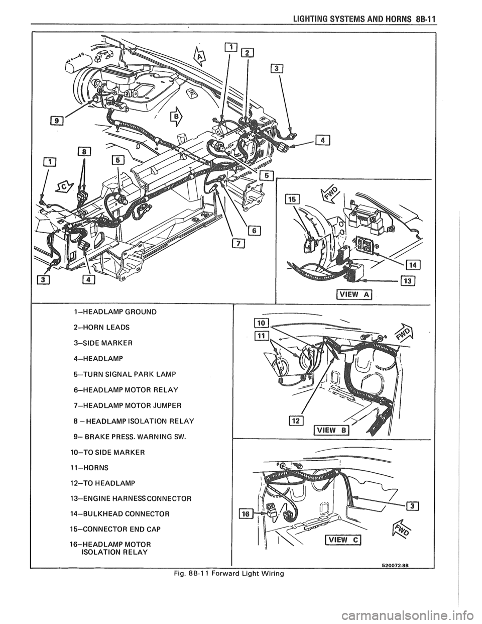
2-HORN LEADS 3-SIDE MARKER
4-HEADLAMP
%-TURN SIGNAL PARK LAMP
6-HEADLAMP MOTOR RELAY
7-HEADLAMP MOTOR JUMPER
8 -HEADLAMP ISOLATION RELAY
9- BRAKE PRESS. WARNING SW.
10-TO
SIDE MARKER
11-HORNS
12-TO
HEADLAMP
13-ENGINE HARNESSCONNECTOR
14-BULKHEAD CONNECTOR
15-CONNECTOR END CAP
16-HEADLAMP MOTOR ISOLATION RELAY
Fig. 8B-1 1 Forward Light Wiring
Page 1664 of 1825
CRUISE CONTROL 9B-1
SECTION 9B
SE CONTROL
CONTENTS
General Description ................................... 9B-1
Off/On/Resume/Accel Switch
Operation
................................................ 9B- 1
Set/Coast Button Switch .............................. 9B- 1
Electronic Controller (Module) .................... 9B-2
Servo Unit ..................................................... 9B-2
Speed Sensors ............................................. 9B-3
VSS Buffer Amplifier ................................ 9B-3
PM Generator Speed Signal ..................... 9B-3
Vacuum Supply ............................................. 9B -4
Electrical and Vacuum Release
Switches
..................................................... 9B-4
Electrical Harness ...................................... 9B-4
Diagnosis .................................................. 9B-4
Cruise System Surges .................................... 9B-4
Cruise Set Speed High or Low ..................... 9B-4
Excessive Cruise Speed Loss on Hills .......... 9B-4
Cruise Tap-Up and Tap-Down .................... 9B-4
On-Gar Service (Illustrated) ..................... 9B-6
Cruise Release Switches ............................... 9B-6
............................. Cruise Processor Module 9B-6
Vacuum Harness and Cable Routing -
VIN E ..................................................... 9B-7
Vacuum Harness and Cable Routing -
VIN S ......................................................... 9B-8
Vacuum Harness and Cable Routing -
VIN F,8 ..................................................... 9B-9
Servo Mounting - VIN S,F .......................... 9B-10
....................... Servo and Bracket - VIN E 9B-10
Vacuum Tank - VIN S,F,E ....................... 9B-10
GENERAL DESCRIPTION
Cruise control is a speed control system which
maintains a desired car speed under normal driving
conditions. However, steep grades up or down may
cause variations in the selected speeds. The electronic
cruise control system has the capability to cruise, coast,
resume speed, accelerate, and "tap-up" and
" tap-down" .
The main parts of the cruise control system are
the mode control switches, controller (module), servo
unit, speed sensor, vacuum supply, electrical and
vacuum release switches, and electrical harness.
The cruise control system uses vacuum to operate
a throttle servo unit. The servo unit maintains a desired
car speed by trapping vacuum in the servo unit at the
proper servo position. The controller monitors vehicle
speed and servo position and operates the vacuum and
vent valves in the servo to maintain desired speed. The
controller contains a low speed limit which will prevent
system engagement below a minimum speed of about
25 mph. The operation of the controller is controlled
by mode control switches located in the end of the
directional signal lever. To disengage the system, two
release switches are provided. An electrical release
switch mounted on the brake pedal bracket (brake and
clutch pedal bracket on cars equipped with manual
transmission) disengages the system electrically when
the brake pedal (or clutch pedal) is depressed. A
vacuum release valve, mounted on the brake pedal
bracket, vents the trapped vacuum in the servo to
atmosphere when the brake pedal is depressed,
allowing the servo unit to quickly return the throttle
to idle position.
.
OFF/ON/RESUME/ACCEL SWITCH
(OPERATION)
Figure 1
The Off/On/Resume/Accel Switch has three
positions. This switch turns the cruise control system
ON and OFF and also returns cruise control operation
to the last speed setting when MOMENTARILY
moved towards the R/A position after braking. (Do
not hold the slider in the R/A position
... release it
immediately.) If the slider is held in the R/A position
for more than one second, the system goes into the
Accel mode. To accelerate the car, move the slider
switch to the R/A position and hold it there until the
car reaches the desired speed. When the slider switch
is released, the system will maintain the new cruise
speed. In order to use the Accel mode, the cruise
OFF/ON/Resume/Accel switch must be in the "ON"
position and the car must be above the low speed limit
of
25 mph.
The slide switch can also be used to "tap-up" car
speed. In order to do this the cruise must be engaged
and operating. "Tapping-up" is done by quickly
pressing the slide switch toward the R/A position and
quickly releasing it, or "tapping" the lever. Do not hold
the lever in the R/A position or the system will go into
the Accel mode. "Tap-up" is a function in which cruise
speed can be increased by
1 mph increments (one tap
= 1 mph increase).
SET/COAST BUTTON SWITCH
Figure 1
The cruise control Set/Coast Switch (located in
the end of the turn signal lever) has two positions
-
"Normal" and "Depressed".
Page 1665 of 1825
98-2 CRUISE CONTROL
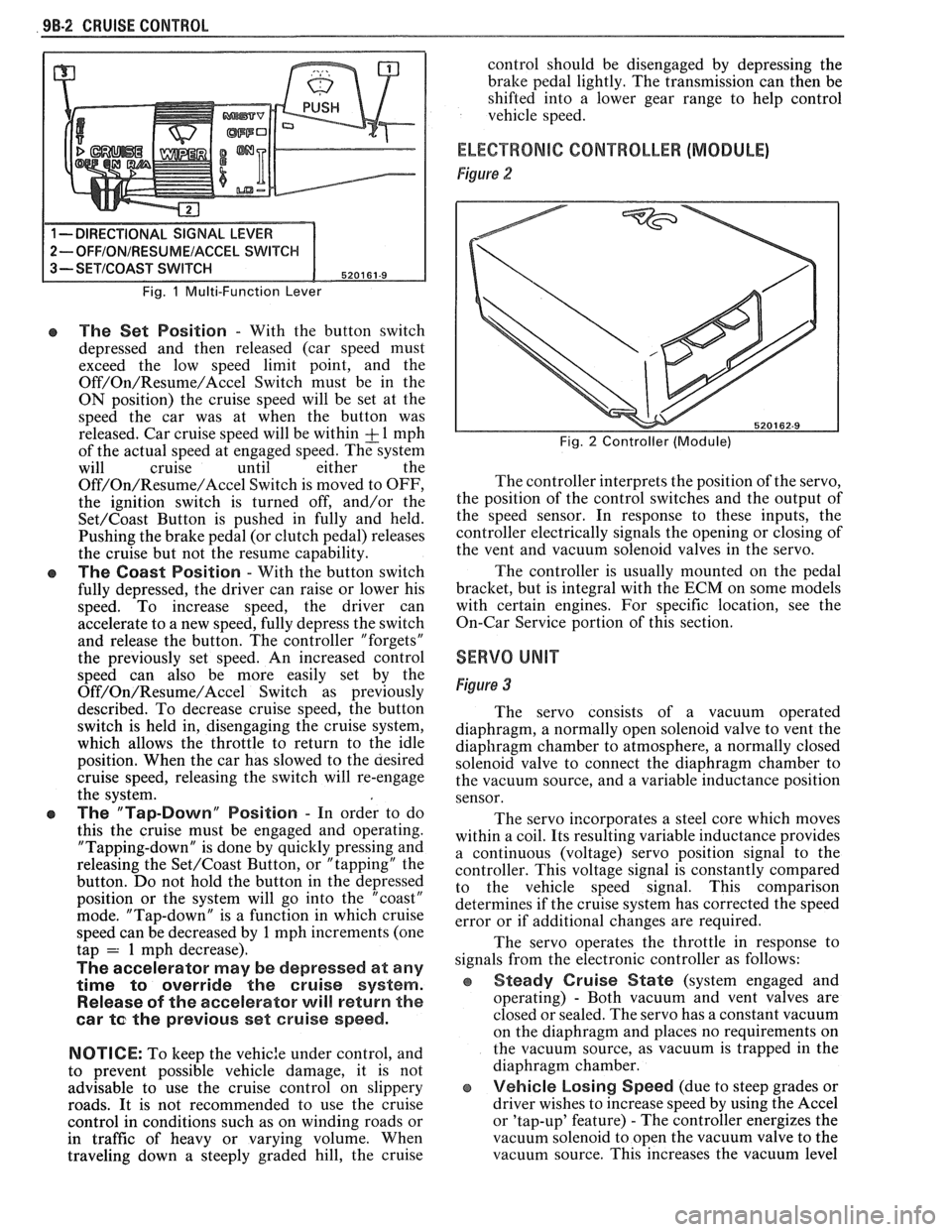
Fig. 1 Multi-Function Lever
e The Set Position - With the button switch
depressed and then released (car speed must
exceed the low speed limit point, and the
Off/On/Resume/Accel Switch must be in the
ON position) the cruise speed will be set at the
speed the car was at when the button was
released. Car cruise speed will be within
& 1 mph
of the actual speed at engaged speed. The system
will cruise until either the
Off/On/Resume/Accel Switch is moved to OFF,
the ignition switch is turned off, and/or the
Set/Coast Button is pushed in fully and held.
Pushing the brake pedal (or clutch pedal) releases
the cruise but not the resume capability.
The Coast Position - With the button switch
fully depressed, the driver can raise or lower his
speed. To increase speed, the driver can
accelerate to a new speed, fully depress the switch
and release the button. The controller "forgets"
the previously set speed. An increased control
speed can also be more easily set by the
Off/On/Resume/Accel Switch as previously
described. To decrease cruise speed, the button
switch is held in, disengaging the cruise system,
which allows the throttle to return to the idle
position. When the car has slowed to the aesired
cruise speed, releasing the switch will re-engage
the system.
e The "Tap-Down" Position - In order to do
this the cruise must be engaged and operating.
"Tapping-down" is done by quickly pressing and
releasing the
Set/Coast Button, or "tapping" the
button. Do not hold the button in the depressed
position or the system will go into the "coast"
mode. "Tap-down" is a function in which cruise
speed can be decreased by
1 mph increments (one
tap = 1 mph decrease).
The accelerator may be depressed at any
time
to override the cruise system.
Release of the accelerator will return the
car
te the previous set cruise speed.
NOTICE:
To keep the vehic:e under control, and
to prevent possible vehicle damage, it is not
advisable to use the cruise control on slippery
roads. It is not recommended to use the cruise
control in conditions such as on winding roads or
in traffic of heavy or varying volume. When
traveling down
a steeply graded hill, the cruise control
should be disengaged by depressing the
bralte pedal lightly. The transmission can then be
shifted into a lower gear range to help control
vehicle speed.
ELECTRONIC CONTROLLER (MODULE)
Figure 2
Fig. 2 Controller (Module)
The controller interprets the position of the servo,
the position of the control switches and the output of
the speed sensor. In response to these inputs, the
controller electrically signals the opening or closing of
the vent and vacuum solenoid valves in the servo.
The controller is usually mounted on the pedal
bracket, but is integral with the ECM on some models
with certain engines. For specific location, see the
On-Car Service portion of this section.
SERVO UNIT
Figure 3
The servo consists of a vacuum operated
diaphragm, a normally open solenoid valve to vent the
diaphragm chamber to atmosphere, a normally closed
solenoid valve to connect the diaphragm chamber to
the vacuum source, and a variable inductance position
sensor.
The servo incorporates a steel core which moves
within a coil. Its resulting variable inductance provides
a continuous (voltage) servo position signal to the
controller. This voltage signal is constantly compared
to the vehicle speed signal. This comparison
determines if the cruise system has corrected the speed
error or if additional changes are required.
The servo operates the throttle in response to
signals from the electronic controller as follows:
Steady Cruise State (system engaged and
operating)
- Both vacuum and vent valves are
closed or sealed. The servo has a constant vacuum
on the diaphragm and places no requirements on
the vacuum source, as vacuum is trapped in the
diaphragm chamber.
e Vehicle Losing Speed (due to steep grades or
driver wishes to increase speed by using the Accel
or 'tap-up' feature)
- The controller energizes the
vacuum solenoid to open the vacuum valve to the
vacuum source. This increases the vacuum level