1988 PONTIAC FIERO relay
[x] Cancel search: relayPage 1382 of 1825
(Continued on next page)
AIR CONDITIONING: COMPRESSOR CONTROLS
C67, ELECTRONlG
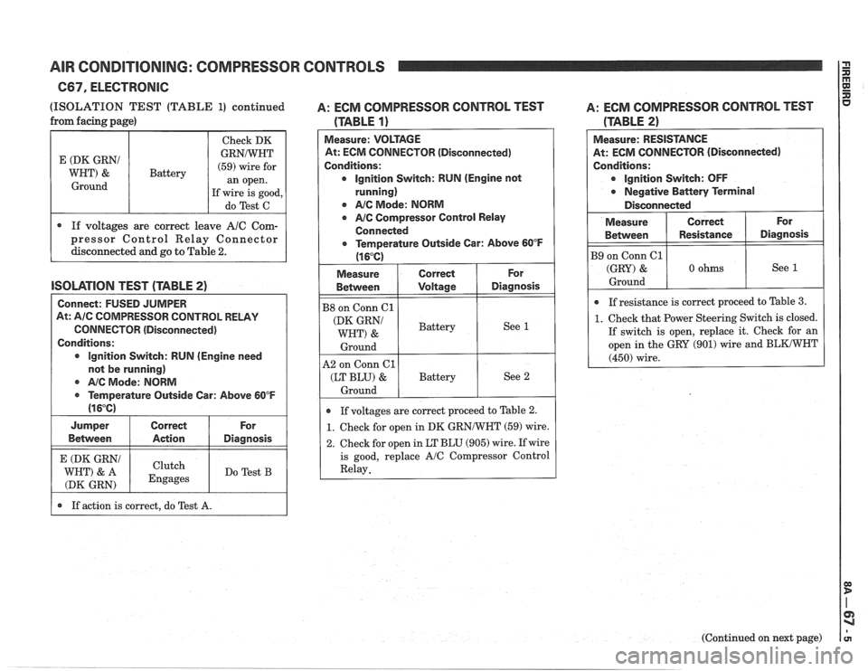
(ISOLATION TEST (TABLE 1) continued A: ECM COMPRESSOR CONTROL TEST A:
ECM COMPRESSOR CONTROL TEST
If action is correct, do Test A.
from
facing page)
(TABLE 2)
Measure: RESISTANCE
At: ECM CONNECTOR (Disconnected)
Conditions:
r Ignition Switch: OFF
.a Negative Banery Terminal
Disconnected
E (DK GRNI
WHT) &
Ground
(TABLE 1)
Measure: VOLTAGE
At: ECM CONNECTOR (Disconnected)
Conditions:
r Ignition Switch: RUN (Engine not
running)
AIC Mode: NORM
AIC Compressor Control Relay
Connected
Temperature Outside Car: Above 60°F
(I 6°C)
For
Diagnosis
See 1
Measure
Between
B9 on Conn 61
(GRY) &
Ground
Battery
.a If
resistance is correct proceed to Table 3.
1. Check that Power Steering Switch is closed.
If switch is open, replace it. Check for an
open in the GRY (901) wire and
BLKIWHT
(450) wire.
Correct
Resistance
0 ohms For
Diagnosis
See 1
See 2
Measure
Behnreen
B8 on Conn Cl
(DK GRNi
WHT) &
Ground
A2 on Conn
61
(LT BLU) &
Ground
Check
DK
GRNNHT
(59) wire for
an open.
If wire is good,
do Test C
If voltages are correct proceed to Table 2.
1. Check for open in DK
GRNNHT (59) wire.
2. Check for open in LT BLU (905) wire. If wire
is good, replace
AIC Compressor Control
- Relay.
Correct
Voltage
Battery
Battery
If
voltages are correct leave
AlC Com-
pressor Control Relay Connector
disconnected and go to Table
2.
lSOLATlON TEST (TABLE 2)
Connect: FUSED JUMPER
At:
AIC COMPRESSOR CONTROL RELAY
CONNECTOR (Disconnected)
Conditions:
Ignition Switch: RUN (Engine need
not be running)
r A/C Mode: NORM
.a Temperature Outside Car: Above 60°F
(1 6°C)
Jumper
Between
E (DK GRNI
WHT) & A
(DK GRN)
Correct
Action
Clutch
Engages
For
Diagnosis
Do Test B
Page 1383 of 1825
AIR CONDITIONING: COMPRESSOR CONTROLS
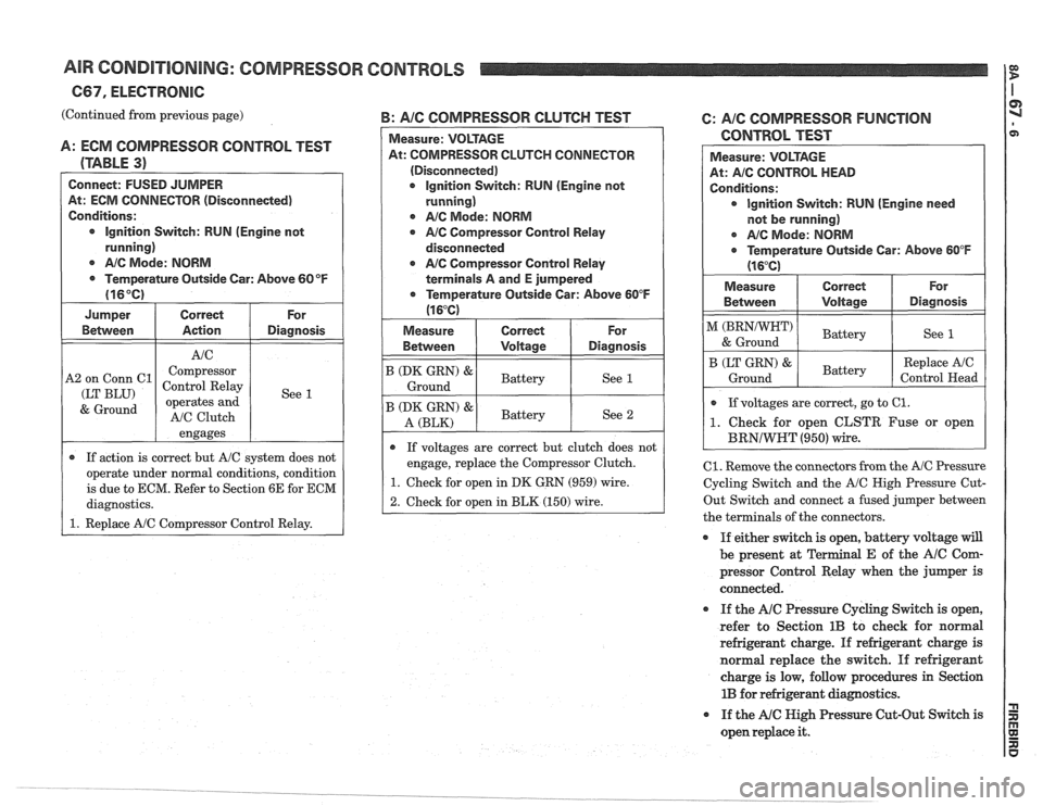
(Continued from previous page) B: AIC COMPRESSOR CLUTCH TEST
A: ECM COMPRESSOR CONTROL TEST
(TABLE
3)
Connect: FUSED JUMPER
At: ECM CONNECTOR (Disconnected)
Conditions: lgnition Switch: RUN (Engine not
running)
@ AIC Mode: NORM
Temperature Outside Car: Above
60 OF
(16°C)
Jumper Correct
Between Action Diagnosis
engages
A2
on Conn
61
(LT BLU)
& Ground
If action is correct but A/C system does not
operate under normal conditions, condition
is due to ECM. Refer to Section 6E for ECM
diagnostics. Compressor
Control Relay
operates and
AfC Clutch
Between 1 Voltage I Diagnosis
Measure:
VOLTAGE
At: COMPRESSOR CLUTCH CONNECTOR
(Disconnected) Ignition Switch: RUN (Engine
not
running)
r AIC Mode: NORM
@ AIC Compressor Control Relay
disconnected
AIC Compressor Control Relay
terminals A and E jumpered
r Temperature Outside Car: Above 60°F
(1 6°C)
See 1
B (DK GRN) & /
Ground I See 1
Measure I Correct
(DK GRN) '1 Battery I See 2 A (BLK)
For
- -
e If voltages are correct but clutch does not
engage, replace the Compressor Clutch.
1. Check for open in DK GRN (959) wire.
2. Check for open in BLK (150) wire.
6: AIC COMPRESSOR FUNCTlON
CONTROL TEST
Measure: VOLTAGE
At: AIC CONTROL HEAD
Conditions: Ignition Switch: RUN (Engine need
not be running)
@ AIC Mode: NORM
Temperature Outside Car: Above
60°F
(16°C)
Measure I Correct
Between Voltage
& Ground
If voltages are correct, go to
61.
1. Check for open CLSTR Fuse or open
For
Diagnosis
See 1
B (LT GRN) &.
Ground -
C1. Remove the connectors from the A/C Pressure
Cycling Switch and the
A/C High Pressure Cut-
Out Switch and connect a fused jumper between
the terminals of the connectors.
If either switch is open, battery voltage will
be present at al E of the AIC Corn-
pressor Control Relay when the jumper is
connected.
Battery
If the Ale Pressure Cycling Switch is open,
refer to Section
1B to check for normal
refrigerant charge. If refrigerant charge is
normal replace the switch. If refrigerant
charge is low, follow procedures in Section
1B for refrigerant diagnostics. Replace
AfC
Control Head
0 If
the NC Nigh Pressure Cut-Out Switch is
open replace
it.
Page 1384 of 1825
AIR CONDITIONING: COMPRESSOR CONTROLS
667, ELECTRONIC
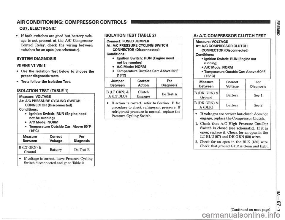
r If both switches are good but battery volt-
age is not present at the
A/C Compressor
Control Relay, check the wiring between
switches for an open (see schematic).
SYSTEM DlPaGNOSlS
V8 VINF, V8 VIN 8
s Use the Isolation Test below to choose the
proper diagnostic tests.
r Tests follow the Isolation Test.
lSOLATlON TEST (TABLE 2)
Connect: FUSED JUMPER
At:
A/C PRESSURE CYCLING SWITCH
CONNECTOR (Disconnected)
Conditions: Ignition Switch: RUN (Engine need
not be running)
Q NC Mode: NORM
Q Temperature Outside Car: Above 60°F
(1 6°C)
I Jumper I Correct I For
lSOLATlOlU TEST (TABLE 1)
I Measure: VOLTAGE
AIC Mode:
NORM
@ Temperature Outside Car: Above 60°F
(1 6°C)
At:
AIC PRESSURE
CYCLING SWITCH
CONNECTOR (Disconnected)
Conditions:
lgnition Switch: RUN (Engine need
not be running) Between
B (LT GRN) &
A (LT
BLU)
If action is correct, refer to Section 1B for
procedure to check refrigerant pressure. If
refrigerant pressure is
normal, replace the
I (zz) & I Battery I Do Test B I
Measure
Between
A: AIC COMPRESSOR CLUTCH TEST
Action
Clutch
Engages
Diagnosis
Do Test A
Correct
Voltage
.
If voltage is correct, leave Pressure Cycling
Switch disconnected and go to Table
2.
Measure: VOLTAGE
At:
A/C COMPRESSOR CLUTCH
CONNECTOR (Disconnected)
Conditions:
lgnition Switch: RUN (Engine not
running)
0 A/C Mode: NORM
Temperature Outside Car: Above
60°F
(16°C)
For
Diagnosis
(Continued on next page)
Measure
Betvveen
B (DK GRN) &
Ground
B (DK GRN) &
A (BLK)
Q If voltages are correct but clutch does not
engage, replace the Compressor Clutch.
1. Check that A/C Nigh Pressure Cut-Out
Switch is closed (see schematic).
If it is
open, replace it. Check for
an open in the
LT BLU (67) and DK GRN (59) wires.
2. Check for an open in the BLK (150) wire.
Check that ground 6112 is clean and tight.
Correct
\joltage
Battery
Battelr
For
Diagnosis
See 1
See 2
Page 1386 of 1825
AIR CONDITIONING: COMPRESSOR CONTROLS
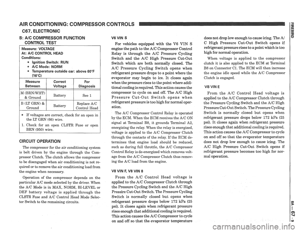
B: AIG COMPRESSOR FUNGTlON
CONTROL TEST
Measure: VOLTAGE
At: AIG CONTROL HEAD
Conditions:
e Ignition Switch: RUN
@ A/C Mode: NORM
@ Temperature outside car: above 60°F
(16°C)
1 Measure I Correct 1 For 1
Between I Voltage I Diagnosis I
1 ) 1 Battery 1 See 1 I
r If voltages are correct, check for an open in
the LT
GRN (66) wire.
B (LT GRN) &.
Ground
1. Check for an open CLSTR Fuse or open
BRN
(950) wire.
The compressor for the air conditioning system
is belt driven by the engine through the Com-
pressor Clutch. The clutch allows the compressor
to be disengaged when air conditioning is not re-
Battery
quired or to remove the air conditioning load from
the engine when necessary. Replace
A/C
Control Head
Operation of the compressor depends on the
particular A/C mode selected by the driver. When
the
A/C Mode is in MAX, NORM, BI-LEVEL or
DEF battery voltage is applied through the
CLSTR Fuse and
A/C Control Head Mode Selec-
tor Switch to the remaining circuits.
V6 VIN S
For vehicles equipped with the V6 VIN S
engine the path to the
A/C Compressor Control
Relay is through the
AlC Pressure Cycling
Switch and the
A16 Nigh Pressure Cut-Out
Switch which are both normally closed. The
Ale Pressure Cycling Switch opens when
refrigerant pressure drops to a point where the
evaporator may begin to ice.
It closes again
when the pressure rises to the point where
addi-
tional cooling is required. This action causes the
compressor to cycle on and off. The
Ale High
Pressure Cut-Out Switch opens when
refrigerant pressure is too high for
nomd oopr-
ation.
The AIC Compressor Control Relay is operated
by the EGM. When the ECM receives the
A/C ON
signal at Terminal
B8, it grounds Terminal A2,
energizing the relay. When the relay is energized,
voltage is applied to the
A/C Compressor Clutch
through the contacts of the relay. If the ECM de-
termines that engine load should be reduced,
such as during full throttle, the
A/C Compressor
Control Relay is de-energized which removes volt-
age from the
A/C Compressor Clutch thus remov-
ing the
A/C load from the engine.
V8 VlN F, V8 VllU 8
From the AlC Control Head voltage is
applied to the
A/@ Cornpressor Clutch through
the Pressure Cycling Switch and the
A/@ High
Pressire Cut-Out Switch. The Pressure Cycling
Switch is normally closed but opens when
refrigerant pressure drops below
172 kPa (25
psi). It closes again when refrigerant pressure
rises enough that additional cooling is required.
This action causes the
A/C Compressor to cycle
on and off so that the evaporator temperature does
not drop low enough to cause icing. The
A/
C High Pressure Cut-Out Switch opens if
refrigerant pressure rises to a point which is too
high for normal operation.
When voltage is applied to the compressor
clutch it is also applied to the ECM at
Terminal
B8 on Connector 61. The ECM will then increase
the engine idle speed while the
A/G Compressor
Clutch is engaged.
From the
AlC Control Head voltage is
applied to the
A/C Compressor Clutch though
the Pressure Cycling Switch and the AIC High
Pressure Cut-Out Switch. The Pressure
Cychg
Switch is normally closed but opens when
refrigerant pressure
drops below 172 kPa (25
psi). It closes again when refrigerant pressure
rises enough that
additional cooling is required.
This action causes the
A/C Compressor to cyde
on and off so that the evaporator teqerature
does not drop low enough to cause icing. The
A/C High Pressure Cut-Out Switch opens if
refrigerant pressure becomes too high for nor-
mal operation.
Page 1442 of 1825
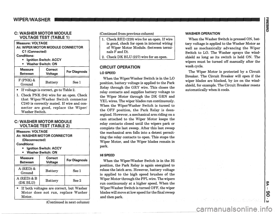
C: WASHER MOTOR MODULE
VOLTAGE TEST (TABLE
1 ) -
Measure: VOLTAGE
At: WIPER MOTOR MODULE CONNECTOR
Cl (Connected)
Conditions:
Ignition Switch: ACCY
Washer Switch: ON
Measure Correct For Diagnosis
Between Voltage
I (PNK'& I Battery I See 1 I Ground
If voltage is correct, go to Table 2.
1. Check PNK (94) wire for an open. Check
that WiperlWasher Switch connector
6240 is correctly mated. If wire and con-
nector are good, replace the Wiper1
Washer Switch.
CfWASHER MOTOR MODULE
VOLTAGE TEST (TABLE
2)
Measure: VOLTAGE
At:
VVASHER MOTOR CONNECTOR
(Disconnected)
Conditions:
Ignition Switch: ACCY
0 Washer Switch: ON
Measure
Between
I ::::ii 1 For Diagnosis I
I A(RED'& I Battery I See 1 I Ground
A (RED' & Battery
(DK BLU) See 2
If both voltages are correct, but Washer
Motor does not run, replace Washer
Motor.
(Continued in next column) (Continued
from previous column)
of Wiper Motor Module. (between
terrni-
nals F and D).
CIRCUIT OPERATION
LO SPEED
When the WiperlWasher Switch is in the LO
position, battery voltage is applied to the Park
Relay through the GRY wire. This closes the
relay contacts and supplies battery voltage to
the Wiper Motor through the DK GRN and
YEL wires. The wiper blades run continuously.
When the WiperIWasher Switch is turned to
the OFF position, the Park Relay is
deen-
ergized. However, a mechanical arm riding on a
cam attached to the Wiper Motor keeps the
relay contacts closed until the wipers park or
complete the last sweep. After this last sweep
the mechanical arm falls into a detent
perrnit-
ting the relay contacts to open. This stops the
Wiper Motor, and the Wiper blades remain in
park.
HI SPEED
When the WiperIWasher Switch is in the Hi
position, the Park Relay is again energized to
relase the latch arm. However, battery voltage
is applied to the high speed brushes of the
Wiper Motor through the PPL wire. The wipers
run continuously at a higher speed. When the
WiperlWasher Switch is turned OFF, the wiper
blades
will move at low speed for the final sweep
and then park.
VVASHER OPERATION
When the Washer Switch is pressed ON, bat-
tery voltage is applied to the Washer Motor
as
well as mechanically advancing the Wiper
Switch to LO. The Washer sprays the wind-
shield as long as its switch is held ON. The
wipers must be turned off manually after the
wash cycle.
The Wiper Motor is protected by a Circuit
Breaker. The Circuit Breaker
will open if the
wiper blades are blocked, by ice on the wind-
shield, for example. The Circuit Breaker resets
automatically when it cools.
Page 1447 of 1825
WIPERIWASHER: PULSE, CB4
(Continued from previous page)
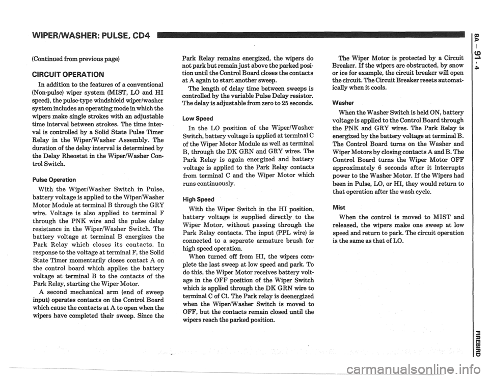
CIRCUIT OPERATION
In addition to the features of a conventional
(Non-pulse) wiper system (MIST, LO and HI
speed), the pulse-type windshield
wiperlwasher
system includes an operating mode in which the
wipers make single strokes with an adjustable
time interval between strokes. The time inter-
val is controlled by a Solid State Pulse Timer
Relay in the WiperIWasher Assembly. The
duration of the delay interval is determined by
the Delay Rheostat
in the WiperIWasher Con-
trol Switch.
Pulse Operation
With the WiperlWasher Switch in Pulse,
battery voltage is applied to the WiperlWasher
Motor Module at terminal
B through the GRY
wire. Voltage is also applied to
terminal F
through the PNK wire and the pulse delay
resistance in the WiperlWasher Switch. The
battery voltage at terminal
B energizes the
Park Relay which closes its contacts. In
response to the voltage at terminal F, the Solid
State Timer momentarily closes contact
A on
the control board which applies the battery
voltage at terminal
B to the contacts of the
Park Relay, starting the Wiper Motor.
A second mechanical arm (end of sweep
input) operates contacts on the Control Board
which cause the contacts at A to open when the
wipers have completed their sweep. Since the Park
Relay remains energized, the wipers do
not park but remain just above the parked posi-
tion until the Control Board closes the contacts
at A again to start
another sweep.
The length of delay time between sweeps is
controlled by the variable Pulse Delay resistor.
The delay is adjustable from zero to
25 seconds.
Low Speed
In the LO position of the WiperIWasher
Switch, battery voltage is applied at terminal C
of the Wiper Motor Module as well as terminal
B, through the DK GRN and GRY wires. The
Park Relay is again energized and battery
voltage is applied to the Park Relay contacts
from terminal
G and the Wiper Motor which
runs continuously.
High Speed
With the Wiper Switch in the HI position,
battery voltage is supplied directly to the
Wiper Motor, without passing through the
Park Relay contacts. The input (PPL wire) is
connected to a separate armature brush for
high speed operation.
When turned off from HI, the wipers com-
plete the last sweep at low speed and park. To
do this, the Wiper Motor receives battery volt-
age
in the OFF position of the Wiper Switch
which is applied through the
DM GRN wire to
terminal C of
61. The Park relay is deenergized
when the WiperlWasher Switch
is moved to
OFF, but the contacts remain closed until the
wipers reach the parked position. The
Wiper Motor is protected by a Circuit
Breaker. If the wipers are obstructed, by snow
or ice for example, the circuit breaker
will open
the circuit. The Circuit Breaker resets automat-
ically when
it cools.
Washer
When the Washer Switch is held ON, battery
voltage is applied to the Control Board through
the PNK and GRY wires. The Park Relay is
energized by the battery voltage at ter
The Control Board turns on the Washer and
Wiper Motors by closing contacts A and
B. The
Control Board turns the Wiper Motor OFF
approximately
6 seconds after it interrupts
power to the Washer Motor. If the Wipers had
been in Pulse, LO, or HI, they would return to
that operation after the wash cycle.
Mist
When the control is moved to MIST and
released, the wipers make one sweep at low
speed and return to park. The circuit operation
is the same as that of LO.
Page 1454 of 1825
HEADLIGHTS: FOG LIGHTS
TROUBLESHOOTING HINTS
r Try the following checks before doing the
System Diagnosis
.
1 . Check that the Headlights and Park Lights
work properly before troubleshooting the
Fog Lights
.
2 . If one Fog Light doesn't work, check the
Fog Light. connections. and wires to the
Fog Light
.
Go to System Diagnosis for diagnostic tests .
SYSTEM DIAGNOSIS
Do the following test if the
operate
.
-., U .
Fog Lights do not
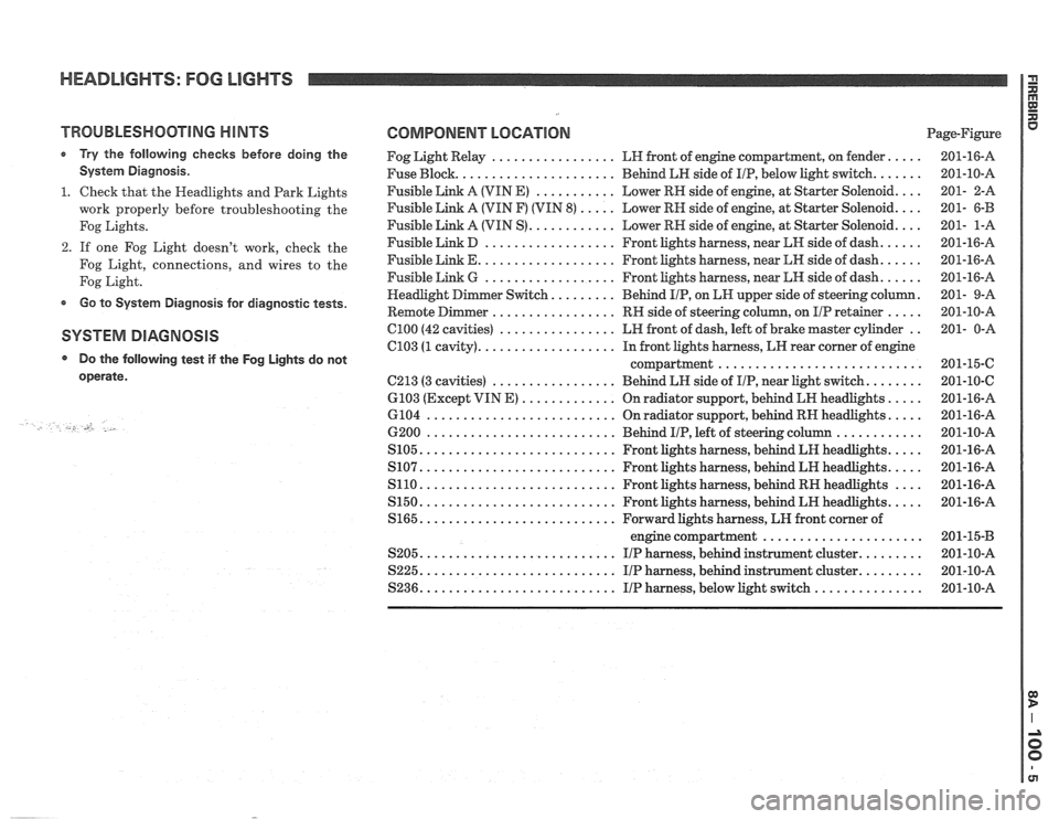
COMPONENT LOCATION Page-Figure
Fog Light Relay
................. LH front of engine compartment. on fender .....
Fuse Block ...................... Behind LH side of IIP. below light switch .......
Fusible Link A (VIN E) ........... Lower RN side of engine. at Starter Solenoid ....
Fusible Link A (VIN F) (VIN 8) ..... Lower RH side of engine. at Starter Solenoid ....
Fusible Link A (VIN S) ............ Lower RH side of engine. at Starter Solenoid ....
Fusible Link D .................. Front lights harness. near kH side of dash ......
Fusible Link E ................... Front lights harness. near LH side of dash ......
Fusible Link 6 .................. Front lights harness. near LN side of dash ......
......... . er Switch Behind IIP. on EN upper side
of steering column
Remote
Dimmer ................. RH side of steering column. on IIP retainer ..... .
C100 (42 cavities) ................ LH front of dash. left of brake master cylinder ..
C103 (1 cavity) ................... In front lights harness. LH rear corner of engine
compartment
............................
C213 (3 cavities) ................. Behind LH side of IIP. near Light switch ........
6103 (Except VIN E) ............. On radiator support. behind LR headlights .....
6104 .......................... On radiator support. behind RN headlights .....
6200 .......................... Behind IIP. left of steering column ............
S105 ........................... Front lights harness. behind LH headlights .....
S107 ........................... Front lights harness. behind LH headlights .....
S110 ........................... Front lights harness. behind RH headlights ....
S150 ........................... Front lights harness. behind LH headlights .....
S165 ........................... Forward lights harness. LH front corner of
engine compartment
......................
S205 ........................... I/P harness. behind instrument cluster .........
S225 ........................... I/P harness. behind instrument cluster .........
S236 ........................... IIP harness. below light switch ...............
Page 1455 of 1825
HEADLIGHTS: FOG LIGHTS
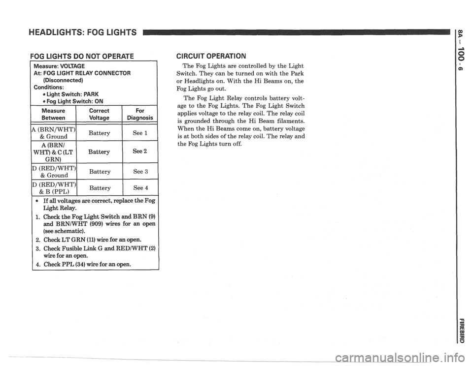
FOG LIGHTS DO NOT OPERATE CIRCUIT OPERATlON
The Fog Lights are controlled by the Light
Switch. They can be turned on with the Park
or Headlights on. With the Hi Beams on, the
Fog Lights go out.
The Fog Light Relay controls battery volt-
age to the Fog Lights. The Fog Light Switch
applies voltage to the relay coil. The relay coil
is grounded through the Hi Beam filaments.
When the Hi Beams come on, battery voltage
is at both sides of the relay coil. The relay and
the Fog Lights turn off.
At: FOG LIGHT RELAY CONNECTOR
(Disconnected)
1. Check the Fog Light Switch and BRN (9)
and BRNIWNT (909) wires for an open
(see schematic).
2. Check LT GRN (11) wire for an open.
3. Check Fusible Link G and RED/WNT (2)