Page 1559 of 1825

POWER ANTENNA
(Continued from previous page) the relay contacts. The motor drives the
Antenna up. At the end of its travel, the Up
Switch opens and the motor stops.
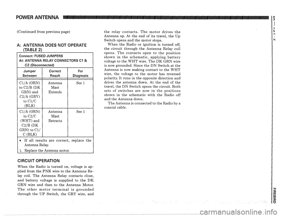
A: ANTENNA DOES NOT OPERATE When the Radio or ignition is turned off,
(TABLE 2) the circuit through the Antenna Relay coil
opens. The contacts open to the position
Connect: FUSED JUMPERS shown in the schematic, applying battery At: ANTENNA RELAY CONNECTORS C1 & voltage to the WHT wire. The DK GRN wire
1 62 (Disconnected) I
Cl/A (ORN)
to
C2/B (DK
GRN) and
C2/A (GRY)
to ci/c
(BLK)
Antenna
Mast
Extends See 1
If all results are correct,
replace the
Antenna Relay.
I 1. Redace the Antenna motor. is
now grounded.
Since the DN Switch at the
Antenna is now making contact to the WNT
wire, the voltage to the motor has reversed
polarity. It runs in the opposite direction and
drives the antenna down. At the end of the
travel, the DN Switch opens the circuit. Both
sets of switches are now in the positions
shown in the schematic with the Radio off
and the Antenna down.
The Antenna
is connected to the Radio by a
coaxial cable.
CIRCUIT OPERATION
When the Radio is turned on, voltage is ap-
plied from the PNK wire to the Antenna Re-
lay coil. The Antenna Relay contacts close,
and battery voltage is supplied to the
DK
GRN wire and then to the Antenna Motor.
The other motor terminal is grounded
through the UP Switch, the GRY wire, and
Page 1564 of 1825
COMPONENT LOCATION VIEWS
ELECTRONIC SPARK
S175 FUEL
PUMP
TIMING (EST) RELAY
DISTRIBUTOR
I TEMPERATURE SWITCH
6143 SENDER Figure
B - RH
Front Corner Of VIM E Engine
Compartment
/ OIL PRESSURE
Figure C
- LH Rear Of VIN E Engine
Page 1566 of 1825
COMPONENT LOCATION VIEWS
ELECTRONIC
EXHAUST GAS
~~~~ S177
RECIRCULATION
(EGR) SOLENOID
AUXILIARY I
COOLANT FAN CANISTER
RELAY PURGE SOLENOID
VALVE
Figure
A - VIN F Engine Compartment (VIN 8 Similar) Figure
B - Rear
Of RH Cylinder Head (VIN E)
6103 IN-LINE
Figure C
- LW Front Corner Of VIN F Engine
Compartment
(VIM 8 Similar)
Page 1568 of 1825
COMPONENT LOCATION VIEWS
COLD START S117 S145
INJECTOR S173
S166 BURN-OFF
CONNECTOR S174 S175 RELAY FUEL
S2 06
1 PUMP
MODULE Figure
B
- RN Rear Side Of VIM F Engine
(VIN 8 Similar)
Figure
C - Top LN Rear Of VIN F Engine
(VIN 8 Sirnilar)
Page 1572 of 1825
COMPONENT LOCATION VIEWS n I =
MODULE CONNECTOR
rgure A - Behind l/P
Figure B - LN Shroud
.-'-- TIMER-RELAY
Figure D
- Behind RN Side Of I/P
Figure E - Below Front Of Console
Page 1574 of 1825
RELEASE
RELAY
A/G TEMPERATURE
DOOR MOTOR
CONNECTOR
Figure
A - Behind RN Side Of I/P
Figure B - Behind Center Of 111"
Figure C - RM Rear Garner Of Engine Camparlment
Page 1586 of 1825
HARNESS CONNECTOR FACES
BLK BLK
NC COMPRESSOR
CONTROL RELAY BLK
NC CONTROL
HEAD (WITH C60)
C304, SEE C303
C1 BLK C2 BLK
AIC CONTROL HEAD (WITH C67)
Page 1587 of 1825
HARNESS CONNECTOR FACES
WHT
A/C TEMPERATURE
DOOR MOTOR
BLK
AIC VACUUM SOLENOID MODULE
BLK
ASSEMBLY
LINE DIAGNOSTIC
LINK (ALDL) CONNECTOR GRY
AUXILIARY COOLANT
FAN RELAY
BLK
BLOWER
HlGH SPEED
RELAY (WITH
C67)
BLK
BLOWER
HlGH SPEED
RELAY (MANUAL AIC)
CRY
BLOWER RESISTORS
BLK
BLOWER SWITCH
C2 BLK
C3 BLU
V00240.0
Brake Switch