1988 PONTIAC FIERO relay
[x] Cancel search: relayPage 1364 of 1825
AIR CONDITIONING: COMPRESSOR CONTROLS
660, MANUAL
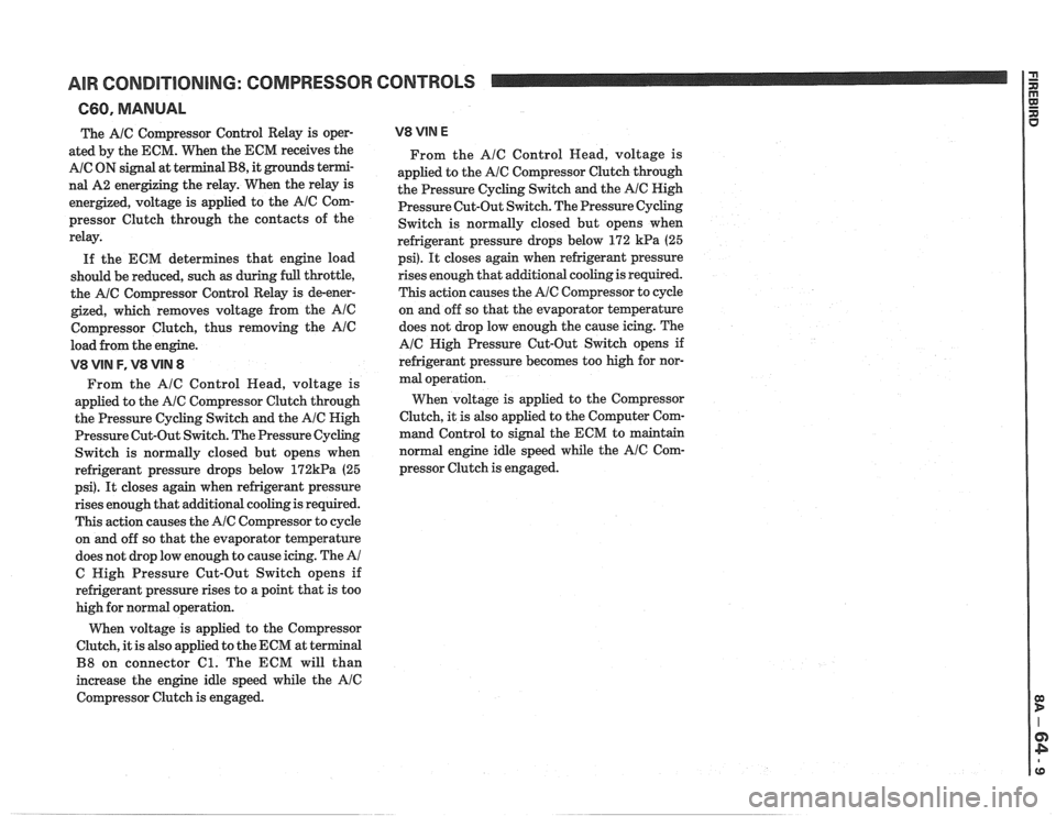
The A/C Compressor Control Relay is oper-
ated by the ECM. When the ECM receives the
A/C ON signal at terminal B8, it grounds termi-
nal A2 energizing the relay. When the relay is
energized, voltage is applied to the
AlC Com-
pressor Clutch through the contacts of the
relay.
If the ECM determines that engine load
should be reduced, such
as during full throttle,
the
A/C Compressor Control Relay is de-ener-
gized, which removes voltage from the Ale
Compressor Clutch, thus removing the Ale
load from the engine.
V8 VIN F, V8 VIN 8
From the A/C Control Read, voltage is
applied to the
A/C Compressor Clutch through
the Pressure Cycling Switch and the
A/C High
Pressure Cut-Out Switch. The Pressure
Cycling
Switch is normally closed but opens when
refrigerant pressure drops below
172kPa (25
psi).
It closes again when refrigerant pressure
rises enough that additional cooling is required.
This action causes the
A/C Compressor to cycle
on and off so that the evaporator temperature
does not drop low enough to cause icing. The
A/
C High Pressure Cut-Out Switch opens if
refrigerant pressure rises to a point that is too
high for normal operation.
When voltage is applied to the Compressor
Clutch, it is also applied to the ECM at terminal
B8 on connector Cl. The ECM will than
increase the engine idle speed while the
Ale
Compressor Clutch is engaged.
V8 VIM E
From the Ale Control Head, voltage is
applied to the
A/C Compressor Clutch through
the Pressure Cycling Switch and the
AIC High
Pressure Cut-Out Switch. The Pressure Cycling
Switch is normally closed but opens when
refrigerant pressure drops below 172
kPa (25
psi).
It closes again when refrigerant pressure
rises
enough that additional cooling is required.
This action causes the
AIC Compressor to cycle
on and off so that the evaporator temperature
does not drop low enough the cause icing. The
A/C High Pressure Cut-Out Switch opens if
refrigerant pressure becomes too high for nor-
mal operation.
When voltage is applied to the Compressor
Clutch, it is also applied to the Computer Com-
mand Control to signal the ECM to maintain
normal engine idle speed while the
Ale Com-
pressor Clutch is engaged.
Page 1371 of 1825
AIR CONDITIONING: BLOWER CONTROLS
TROUBLESHOOTING NlNTS
a Try the following checks before doing the
System Diagnosis
.
1 . Check the HTR A/C Fuse by visual inspection .
2 . Check that 6112 is clean and tight .
3 . Check that Blower Motor connectors and
Blower Relay are mated correctly and firmly
seated
.
a Go the the AIC Systern Check in 813-62 for a
guide to normal operation
.
Go to Systern Diagnosis in this section for
diagnostic tests
.
SYSTEM DIAGNOSIS
Do the tests listed for your symptom in the
Symptom Table below
.
Tests follow the Symptom Table .
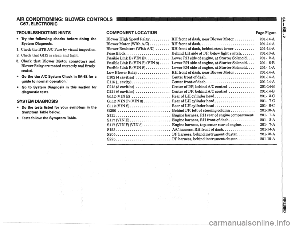
COMPONENT LOCATION Page-Figure
Blower High Speed Relay
.......... RH front of dash. near Blower Motor ..........
Blower Motor (With AIC) .......... RH front of dash ...........................
Blower Resistors (With AIC) ....... RH front of dash. behind strut tower ..........
...................... Fuse Block
Behind LH side of IIP. below light switch .......
............ Fusible Link B (VIN E) Lower RH side of engine. at Starter Solenoid ....
Fusible Link B (VIN F) (VIN 8) ..... Lower RH side of engine. at Starter Solenoid ....
............ Fusible Link B (VIN S) Lower RN side of engine. at Starter Solenoid ....
................ Low Blower Relay RH front of dash. near Blower Motor ..........
........................ ................. C102 (4 cavities) Center
front of dash
................... ........................ C115 (1 cavity) Center
front of dash
................. ............. C215 (3 cavities) Center
of IIP. behind AlC control
................. ............. 6224 (6 cavities) Center
of IIP. behind Ale control
................... .................... 6112 (VIN E) Rear of LH cylinder head
............. .................... 6112 (VIN F) (VIN 8) Rear of LH cylinder head
.................... .................... 6112 (VIN S) Rear
of LN cylinder head
.......................... ............ 6200 Behind I/P. left of steering column
........................... Slll Engine harness. RN rear of engine compartment
.................... ............. S117 (VIN E) Engine harness. RH front of dash
............. ....... S117 (VIN F) (VIN 8) Engine harness. top center rear of engine
........................... ................ S153 AIC harness. RH front of dash
........................... ......... S205 IIP harness. behind instrument cluster
........................... S225 IIP harness. behind instrument cluster .........
Page 1372 of 1825
AIR CONDITIONING: BLOWER CONTROLS
C67, ELECTRONIC
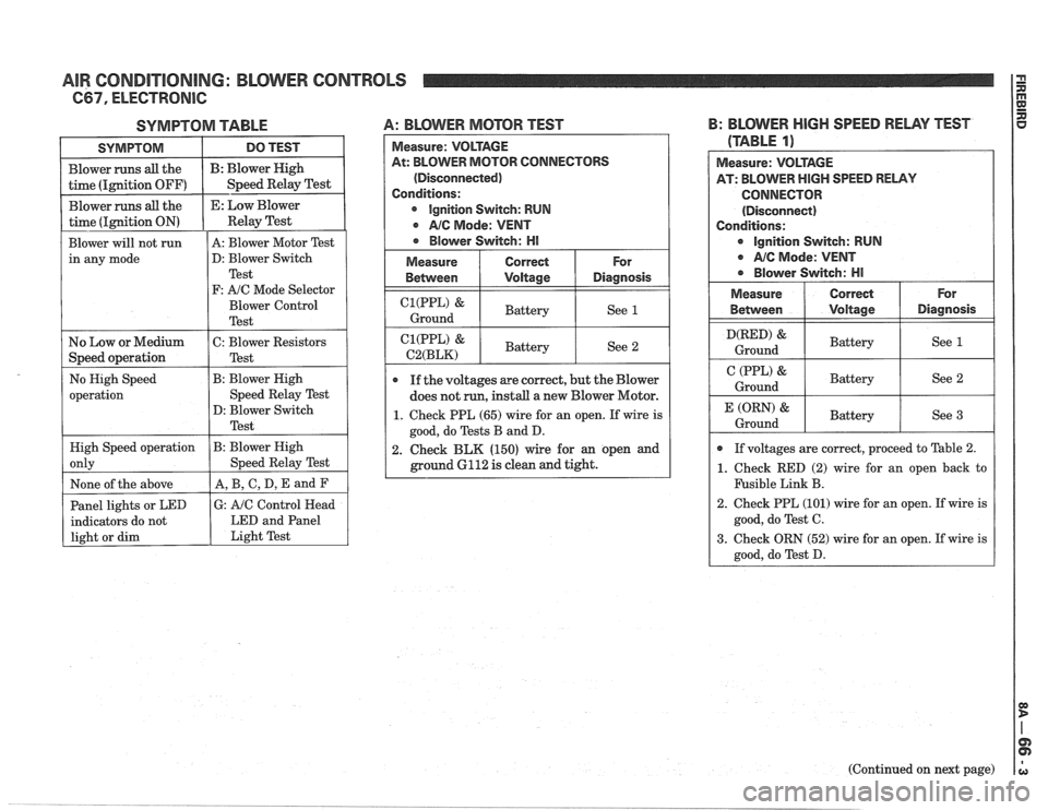
SYMPTOM TABLE 4: BLOVVER MOTOR TEST
Measure: VOLTAGE
At: BLOWER MOTOR CONNECTORS
(Disconnected)
Conditions:
r Ignition Switch: RUN
NC Mode: VENT
e Blower Switch: HI
I C2:zt;)d& I Battery I See 1 I
Measure
Between
& Battery See 2
If the voltages are correct, but the Blower
does not
run, install a new Blower Motor.
Correct
Voltage
1. Check PPL (65) wire for an open. If wire is
good, do Tests B and
D.
For
Diagnosis
1 2. Check BLK (150) wire for an open and
ground
6112 is clean and tight.
B: BLOWER HIGH SPEED RELAY TEST
(TABLE
11
I D(RED) Ground & I Battery I See 1 I
Measure: VOLTAGE
AT: BLOWER HIGH SPEED RELAY
CONNECTOR (Disconnect)
Conditions:
ignition Switch: RUN
r AIC Mode: VENT
r Blower Switch: HI
I (PPL) & 1 Battery
Ground I See 2 I
For
Diagnosis
Measure
Between
a If voltages are correct, proceed to Table 2.
1. Check RED (2) wire for an open back to
F'usible Link B.
2. Check PPL (101) wire for an open. If wire is
good, do Test
C.
3. Check ORN (52) wire for an open. If wire is
good, do Test
D.
Correct
Voltage
(ORN) &
Ground
(Continued on next page)
Battery
See 3
Page 1373 of 1825
AIR CONDITIONING: BLOWER CONTROLS
(Continued from previous page)
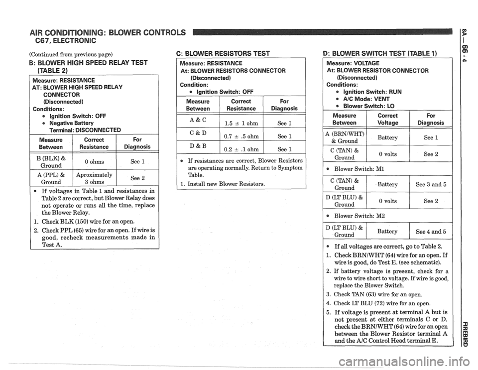
B: BLOWER HIGH SPEED RELAY TEST
(TABLE
2)
Measure: RESISTANCE
AT: BLOWER
HIGH SPEED RELAY
CONNECTOR (Disconnected)
Conditions:
o lgnition Switch: OFF
o Negative Battery
Terminal: DISCONNECTED
( Measure I Correct I For 1
Between I Resistance I Diagnosis
B (BLK) & 0 ohms
Ground
Ground
3 ohms
0 If voltages in Table 1 and resistances in
Table 2 are correct, but Blower Relay does
not operate or runs
all the time, replace
the Blower Relay.
1. Check BLK (150) wire for an open.
6: BLOVVER RESlSTORS TEST D: BLOVVER SWITCH TEST (TABLE 1)
2.
Check PPL (65) wire for an open. If wire is
good, recheck measurements made in
Test A.
Measure: RESISTANCE
At: BLOWER RESISTORS CONNECTOR
(Disconnected)
Condition:
Ignition Switch: OFF
Measure
Between
A&C
C&D
D&B
OR CONNECTOR
(Disconnected)
lgnition Switch: RUN
AIC Mode: VENT
Blower Switch: M2
If
resistances are correct, Blower Resistors
are operating normally. Return to Symptom
Table.
1. Install new Blower Resistors.
Correct
Resistance
1.5 rt. 1 ohm
0.7
+ .5 ohm
0.2
rt. .l ohm
D (LT BLU) &
Ground
For
Diagnosis
See 1
See 1
See 1
If all voltages are correct, go to Table 2.
1. Check BRNIWNT (64) wire for an open. If
wire
is good, do Test E. (see schematic).
2. If battery voltage is present, check for a
wire to wire short to voltage. If wire is good,
replace the Blower Switch.
3. Check TAN (63) wire for an open.
4. Check LT BLU (72) wire for an open.
5. If voltage is present at terminal A but is
not present at either terminals C or
D,
check the BRNIWHT (64) wire for an open
between the Blower Resistor terminal A
and the AlC Control Head terminal E.
Battery See 4 and 5
Page 1374 of 1825
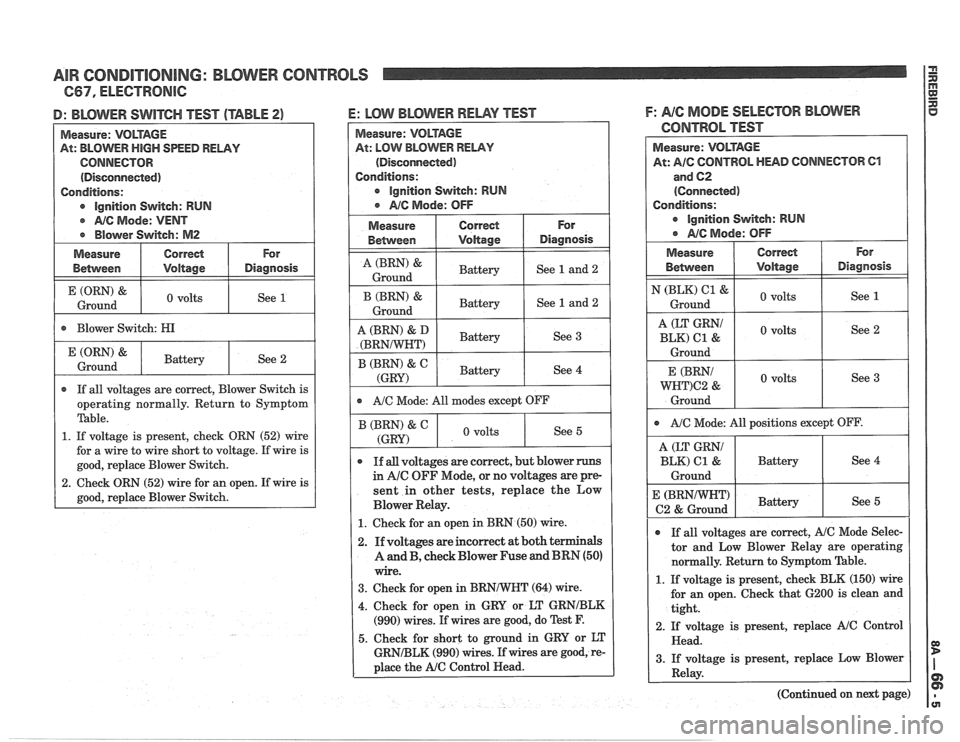
AIR CONDITIONING: BLOWER CONTROLS
I): BLOWER SWITCH TEST (TABLE 23
Measure: VOLTAGE
At: BLOWER
HIGH SPEED RELAY
CONNECTOR
(Disconnected)
Conditions:
e lgnition Switch: RUN
e NC Mode: VENT
@ Blower Switch: M2
I E(ORN)& 1 0 volts
Ground
Measure
Between
I . Blower Switch: HI I
Correct
Voltage
If all voltages are correct, Blower Switch is
operating normally. Return to Symptom
'Pable.
1. If voltage is present, check ORN (52) wire
for a wire to wire short to voltage. If wire is
good, replace Blower Switch.
2. Check ORN (52) wire for an open. If wire is
good, replace Blower Switch.
For
Diagnosis
(ORN) &
Ground
E: LW BLOWER RELAY TEST
Measure: VOLTAGE
At: LOW BLOWER
RELAY
(Disconnected)
Conditions:
e lgnition Switch: RUN
1 a NC Mode: OFF
Battery See 2
I A Ground (BRN) & I Battery I See 1 and 2 1
Measure
Between
I I Battery I see 3 I
Correct
Voltage
(BRN) &
Ground
For
Diagnosis
1 r A/C Mode: All modes except OFF I
Battery
B (BRN) & C
(GRY)
See 1 and 2
If all voltages are correct, but blower runs
in
Ale OFF Mode, or no voltages are pre-
sent in other tests, replace the Low
Blower Relay.
1. Check for an open in BRN (50) wire.
Battery
B (BRN) & C
(GRY
2. If voltages are incorrect at both terminals
A and B, check Blower Fuse and BRN (50)
wire.
3. Check for open in BRNNVHT (64) wire.
4. Check for open in GRY or LT GRNIBLK
(990) wires. If wires are good, do Test F.
5. Check for short to ground in GRY or LT
GRNIBLK (990) wires. If wires are good, re-
place the
A/C Control Head. See
4
F: NG MODE SELECTOR BLOWER
CONTROL TEST
, volts See 5
Measure: VOLTAGE
At: AIG CONTROL HEAD CONNECTOR C1
and 62
(Connected)
Conditions:
e lgnition Switch: RUN
a MC Mode: OFF
I ~EEZ I 0 volts 1 See 2 1
N (BLK) 61 &
Ground
Ground
For
Diagnosis I Measure
Betvveen
I $2 I 0 volts I See 3 1
Correct
bltage
volts
Ground See
1
A/C Mode:
All positions except OFF.
A (LT GW
BLK) 61 & Battery
Ground
@ If all voltages are correct, A/C Mode Selec-
tor and Low Blower Relay are operating
normally. Return to Symptom
'Pable.
E (BRNNVHT)
62 & Ground
1. If voltage is present, check BLK (150) wire
for an open. Check that
6200 is clean and
tight.
2. If voltage is present, replace
A/C Control
Head.
3. If voltage is present, replace Low Blower
Relay.
(Continued on next page)
Battery See 5
Page 1375 of 1825
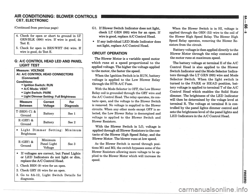
AIR CONDITIONING: BLOWER CONTROLS
C67, ELECTRONIC
(Continued from previous page)
GRNIBLK (990) wire. If wire is good, do
Test
E.
5. Check for open in BRNNHT (64) wire. If
wire is good, do Test
E.
6: A/C CONTROL HEAD LED AND PANEL
LIGHT TEST
Measure: VOLTAGE
At:
A/C CONTROL HEAD CONNECTORS
(Connected)
Conditions: Ignition Switch: RUN
@ AIC Mode: VENT
* Light Switch: PARK
Light Dimmer Setting:
Full Brightness
I (GRY) & I Battery / See 2 1 Ground
Measure
Bemeen
T (BRN) C1 &
Ground
Light Dinimer Setting: Minimum
Brightness
Correct
Voltage
Battery
If voltages are correct, but Panel Lights
or LED Indicators do not light or dim,
replace the
AlC Control Head.
1. Check BRN (9) wire for an open.
For
Diagnosis
See 1
(GRY) '
Ground
61. If Blower Switch Indicator does not light,
check LT GRN (991) wire for an open. If
wire is good, replace
AlC Control Read.
* If any individual LED Mode Indicator does
not light, replace
AlC Control Head.
CIRCUIT OPERATION
The Blower Motor is a variable speed motor
which runs at a speed proportional to the
applied voltage. The higher the voltage applied
to the motor, the faster the speed.
When the Ignition Switch is
in RUN, battery
voltage is applied to the Low Blower Relay
through the
NTR-AIC Fuse.
With the Mode Selector in OFF, the Low Blower
Relay coil is grounded through the GRY wire and
the
A/C Control Head. The relay operates, its con-
tacts open, and the voltage to the Blower Switch
is removed. No voltage is supplied to the Blower
circuits. When any other mode except OFF is se-
lected, the Low Blower Relay is deenergized and
voltage is applied to the Blower Switch and
Blower Resistors.
With the Blower Switch in LO, voltage is
applied through
all Blower Resistors to the con-
tacts of the Blower High Speed Relay, and the
Minimum
Panel Light Voltage
- -
Blower Motor. The blower runs at low speed.
As the Blower Switch is moved through posi-
tions
M1 and M2, the switch bypasses some of the
Blower Resistors allowing more voltage to be ap-
plied to the Blower Motor which will increase its
speed.
See
3
When
the Blower Switch is in HI, voltage is
applied through the ORN (52) wire to the coil of
the Blower Nigh Speed Relay. The Blower Nigh
Speed Relay operates, removing the Blower Re-
sistors from the circuit.
Battery voltage is then applied directly to the
Blower Motor through the relay contacts and
the motor runs at maximum speed.
The battery voltage at
t
Control Read is also applied to the Blower
Switch Indicator and the Mode Selector Indica-
tors through the LT GRN (991) wire and Mode
Selector Switch. When the light switch is
turned to the PARK or HEAD position, bat-
tery voltage is applied to terminal T of the
AIC
Control Head which enables the Solid State
dimmer. The brightness of the LED Indicator
will then be det
terminal R. The volt
trolled by the panel
sets the brightness level of the panel lights and
LED Indicators in the
AIC Control Head.
1 2. Check GRY (8) wire for an open. I
3. Go to 8A-12, Light Switch Details for
diagnosis.
Page 1380 of 1825
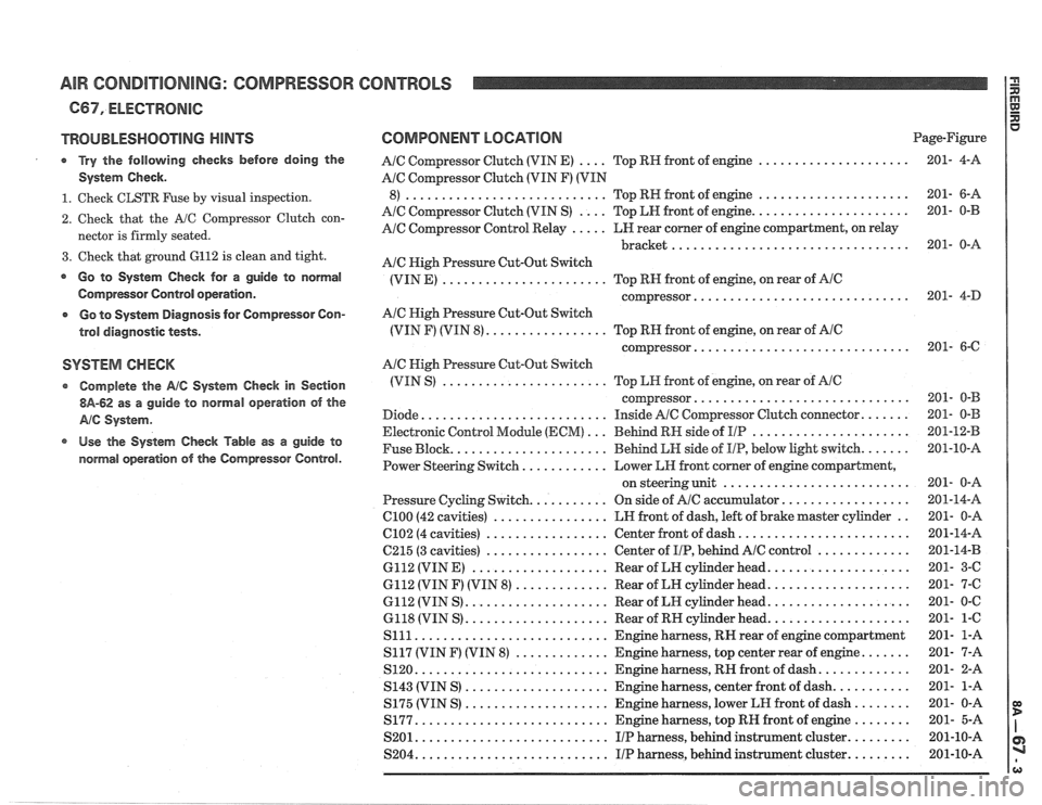
AIR CONDITIONING: COMPRESSOR CONTROLS
C67. ELECTRONIC
TROUBLESHOOTING HINTS
Try the following checks before doing the
System Check
.
1 . Check CLSTR Fuse by visual inspection .
2 . Check that the A/C Compressor Clutch con-
nector is firmly seated
.
3 . Check that ground 6112 is clean and tight .
Go to System Check for a guide to normal
Compressor Control operation
.
o Go to System Diagnosis for Compressor Con-
trol diagnostic tests
.
SYSTEM CHECK
Complete the AIC System Check in Section
$A-62 as a guide to normal operation of the
AIC System .
Use the sy&esla Check Table as a guide to
normal operation
of the Compressor Control .
COMPONENT LOCATION Page-Figure
.... ..................... A/C Compressor Clutch (VIN E) Top
RH front of engine 201-
4-A
AIC Compressor Clutch (VIN F) (VIN
..................... ............................ 8) Top RN front of engine 201- 6-A
.... ...................... A/C Compressor Clutch (VIN S) Top LH front of engine 201-
0-B
A/C Compressor Control Relay ..... LN rear comer of engine compartment. on relay
................................. bracket 201- 0-A
Ale High Pressure Cut-Out Switch
(VIN E)
....................... Top RH front of engine. on rear of AIC
.............................. compressor 201- 4-D
AIC High Pressure Cut-Out Switch
(VIN F) (VIN 8)
................. Top RN front of engine. on rear of AlC
.............................. compressor 201- 6-C
A/C Nigh Pressure Cut-Out Switch
(VIN S)
....................... Top LH front of engine. on rear of AIC
.............................. coqressor 201- 0-B
Diode
.......................... Inside AIC Compressor Clutch connector ....... 201- 0-B
Electronic Control Module
(ECM) ... Behind RH side of I/P ...................... 201-12-B
Fuse Block
...................... Behind LH side of IIP. below light switch ....... 201-10-A
Power Steering Switch
............ Lower LH front comer of engine compartment.
.......................... on steering unit 201- 0-A
Pressure Cycling Switch
........... On side of Ale accumulator .................. 201-14-A
ClOO (42 cavities) ................ LN front of dash. left of brake master cylinder .. 201- 0-A
6102 (4 cavities) ................. Center front of dash ........................ 201-14-A
6215 (3 cavities) ................. Center of I/P. behind AlC control ............. 201-14-B
6112 (VIN E)
................... Rear of LH cylinder head .................... 201- 3-C
6112 (VIN F) (VIN 8)
............. Rear of LH cylinder head .................... 201- 7-6
6112 (VIN S) .................... Rear of LH cylinder head .................... 201- 0-C
6118 (VIN S)
.................... Rear of RH cylinder head .................... 201- 1-6
S111 ........................... Engine harness. RH rear of engine compartment 201-
1-A
S117 (VIN
F) (VIN 8) ............. Engine harness. top center rear of engine ....... 201- 7-A
S120
........................... Engine harness. RIP front of dash ............. 201- 2-A
S143 (VIN S)
.................... Engine harness. center front of dash ........... 201- 1-A
S175 (VIN S)
.................... Engine harness. lower LH front of dash ........ 201- 0-A
S177
........................... Engine harness. top RH front of engine ........ 201- 5-A
S201
........................... IIP harness. behind instrument cluster ......... 201-10-A
S204
........................... I/P harness. behind instrument cluster ......... 201-10-A
Page 1381 of 1825
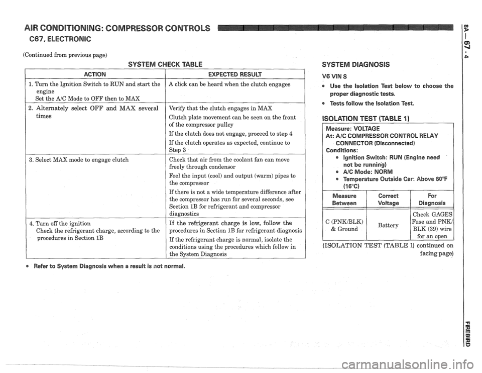
AIR CONDITIONING: COMPRESSOR CONTROLS
667, ELECTRONIC:
(Continued from previous page)
SYSTEM CHECK TABLE SYSTEM DIAGNOSIS
times
ACTION
1. Turn the Ignition Switch to RUN and start the
engine
Set the
A/C Mode to OFF then to MAX
2. Alternately select OFF and MAX several
Clutch plate movement can be seen on the front
1 ISOLATION TEST (TABLE I) of the compressor pulley
1 I If the clutch does not engage, proceed to step 4 (
EXPECTED RESULT
A click can be heard when the clutch engages
Verify that the clutch engages in MAX
If the clutch operates as expected, continue to
1 St€??J 3 I
V6 VIN S
r Use the isolation Test below to choose the
proper diagnostic tests.
Tests follow the isolation Test.
3. Select MAX mode to engage clutch Check
that air from the coolant fan can move
freely through condensor
Feel the input (cool) and output (warm) pipes to
the compressor
If there is not a wide temperature difference after
the compressor has run for several seconds, see
Section
1B for refrigerant and Compressor
diagnostics
4. Turn off the ignition
Check the refrigerant charge, according to the
procedures in Section
1B
If the refrigeramt charge is low, follow the
procedures in Section
1B for refrigerant diagnosis
If the refrigerant charge is normal, isolate the
conditions using the procedures which follow in
the System Diagnosis
(ISOLATION TEST (TABLE 1) continued on
facing page)
Measure: VOLTAGE
At: AIC COMPRESSOR CONTROL RELAY
CONNECTOR (Disconnected)
Conditions:
ignition Switch: RUN (Engine need
not
be running)
c A/@ Mode: NORM
* Temperature Outside Car: Above 60°F
(16°C)
Refer to System Diagnosis when a result is not normal. Measure
Between
C (PNKIBLK)
& Ground
Correct
Voltage
Battery
For
Diagnosis
Check GAGES
Fuse and PNKi
BLK (39) wire
for an open