Page 1588 of 1825
HARNESS CONNECTOR FACES
BURN-OFF RELAY, SEE AUXILIARY
COOLANT FAN RELAY
BLK
CLUTCH START SWITCH
V00491.1
COOLANT FAN RELAY, SEE
AUXILIARY COOLANT FAN RELAY
CRUISE CONTROL SERVO
V00459 0
BLK
CONVENIENCE CENTER
V00275 1
CRUISE CONTROL MODULE
V00286 0
WHT
DEFOGGER CONTROL
V00569 0
BLK
DEFOGGER
TIMER RELAY
V0056 1 0
WHT
DOME LIGHT
V00570.0
Page 1590 of 1825
FOG LIGHT SWITCH,
SEE DEFOGGER CONTROL
WHY
FRONT POWER WINDOW
SWITCH (LH)
V00487 1
BLU
FRONT POWER
WINDOW SWITCH (RH)
V00571 0
FUEL PUMP RELAY, SEE A/C
COMPRESSOR CONTROL RELAY
BRN
FUEL PUMP SWITCH
(V8 VIM F) (V8 VIN 8)
V00?49 0
GEAR SELECTOR SWITCH
V00541 1
GENERATOR
V00176 0
C1 BLK CZ BLK
HATCH COWTACT ASSEMBLY
V00235.0
C1 BLK CP BLK
HEADLIGHT DOOR MODULE
V00512.0
Page 1592 of 1825
HARNESS CONNECTOR FACES
C1 BRN C2 CRY
INSTRUMENT PANEL
(WITHOUT DIGITAL CLUSTER)
V00324 1
BLK
LIGHTS MONITORING MODULE BLK
LUMBAR PUMPIMOTOR
VOOl22 0
BLK
LOW BLOWER RELAY
V00573 0
BLK
LUMBAR
PUMPIMOTOR
RELAY
V00137.2
C2 WWT
Page 1602 of 1825

LIGHTING SYSTEMS AND HORNS 8B-3
HORNS the steering wheel sounds the horn by closing the horn
relay (in the convenience center behind the instrument
panel, to the right of the steering column). The horns
The holm(§) are mounted behind the front fascia use a solenoid-operated diaphragm to generate sound.
on the driver's side. $ushing the pad in the center of See Section 8A-40 for wiring and circuit information.
ON-CAR SERVICE
Wiring diagrams and other diagnosis information
is given in Section
8A. Information on properly
repairing wiring harnesses, connectors, etc., is on
8A-5.
Most lighting problems are caused by loose
connectors, open or shorted wiring, burned-out bulbs,
bad switches, inadequate ground or blown fuses. Many
of these require only replacement of a defective part.
When replacing a part that requires a special procedure
(such as a lens and housing assembly sealed together),
follow the instructions normally included in the
replacement parts package.
When removing a part that requires special
sealing items (such as sealing washers), be sure to
reinstall those items when replacing the part. Also, if
any body sealing items (grommets, etc.) are disturbed,
be sure to repair them so the passenger compartment
remains properly sealed.
EXTERlOR LIGHTS
BACK-UP LIGHTS
Fig. 8B-8
Replacement Bulb: Trade No. 1156, 32
Candlepower
To replace a back-up light bulb, see "Rear
Tail/Stop/Turn Signal Lights9' in this section. For
information on the back-up light switch on the
transmission, see Section
7.
CENTER HIGH-MOUNTED STOPLIGHT
Fig. 8B-7
Assembly Replacement
Remove or Disconnect
1. Spoiler (see Body Service Manual, Section 7H)
2. Four nuts from assembly
3. Stoplight assembly
Install or Connect
1. Stoplight assembly
2. Four nuts
3. Spoiler
Bulb Replacement
Replacement Bulb: Trade No. 577, 21
Candlepo wer
Remove or Disconnect
1. Two screws from lens
2. Lens
3. Bulb from socket
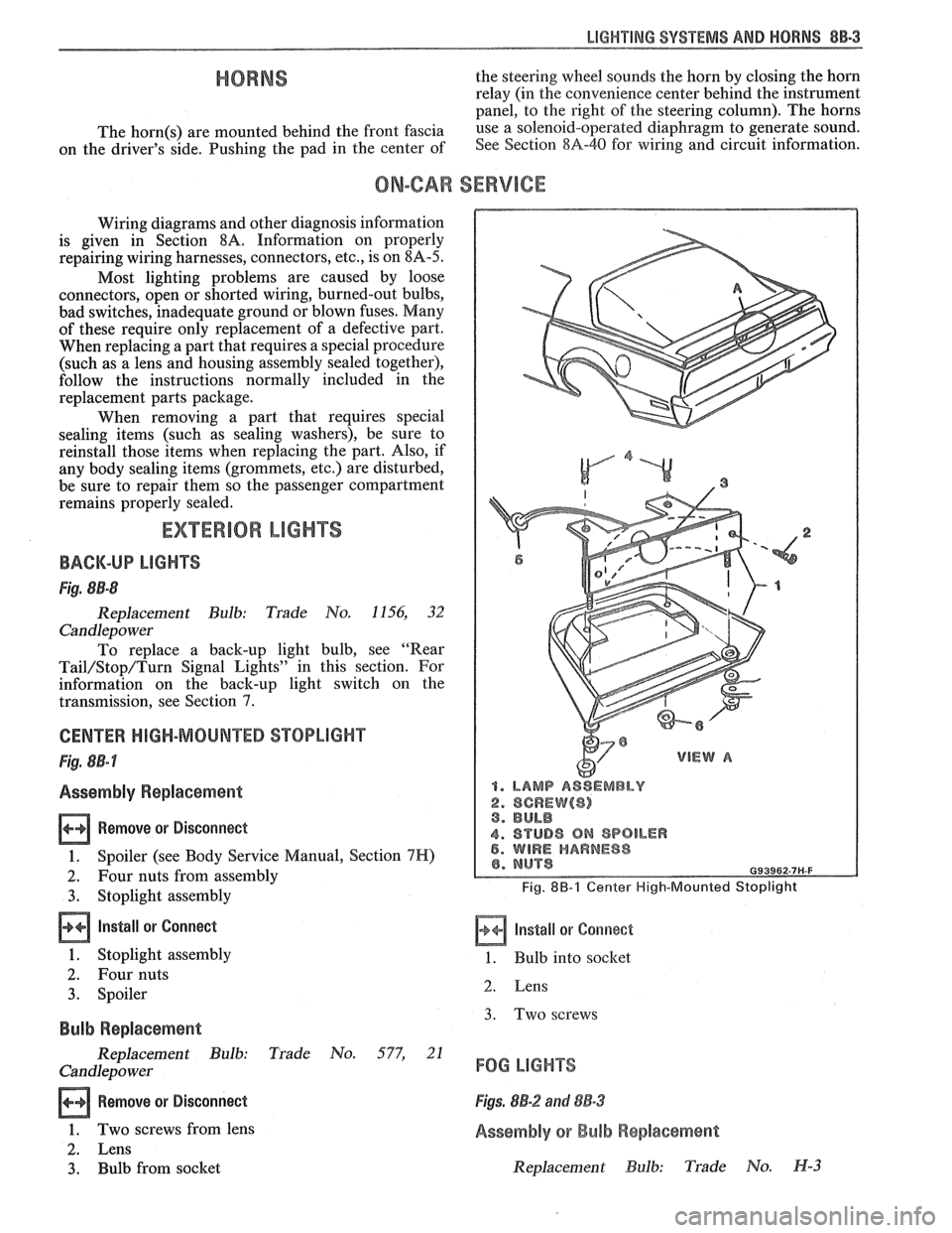
1. LAMP ASSEMBLY
2. SCREW($) 3. BULB
4. STUD8 ON SPOILER 5. WIRE HARNESS
Fig. 8B-1 Center High-Mounted Stoplight
Install or Corrnect
1. Bulb into socket
2. Lens
3. Two screws
FOG LIGHTS
Figs. 8B-2 and 88-3
Assembly or Bulb Replacement
Replacement Bulb: Trade No. H-3
Page 1609 of 1825

Adjust 2 . Filler panel 3 . Electrical connector
1 . Increase Current - Turn adjusting screw 4 . ~~l~/~~~~~
clockwise 5 . Horn
2 . Decrease Current . Turn adjusting screw
counterclockwise
Install or Connect
3 . Current adjustments should be made 1/4 turn
(90") at a time
Horn Assembly
Remove or Disconnect
1 . Six screws from filler panel behind front fascia on
driver's side 1
. Horn
2 . Bolt/screw
3 . Electrical connector
4
. Filler panel
5 . Six screws
Horn Relay
The horn relay is in the convenience center.
behind the instrument panel to the right of the steering
column
. To remove the relay. pull it straight out .
REPLACEMENT LIGHT BULBS
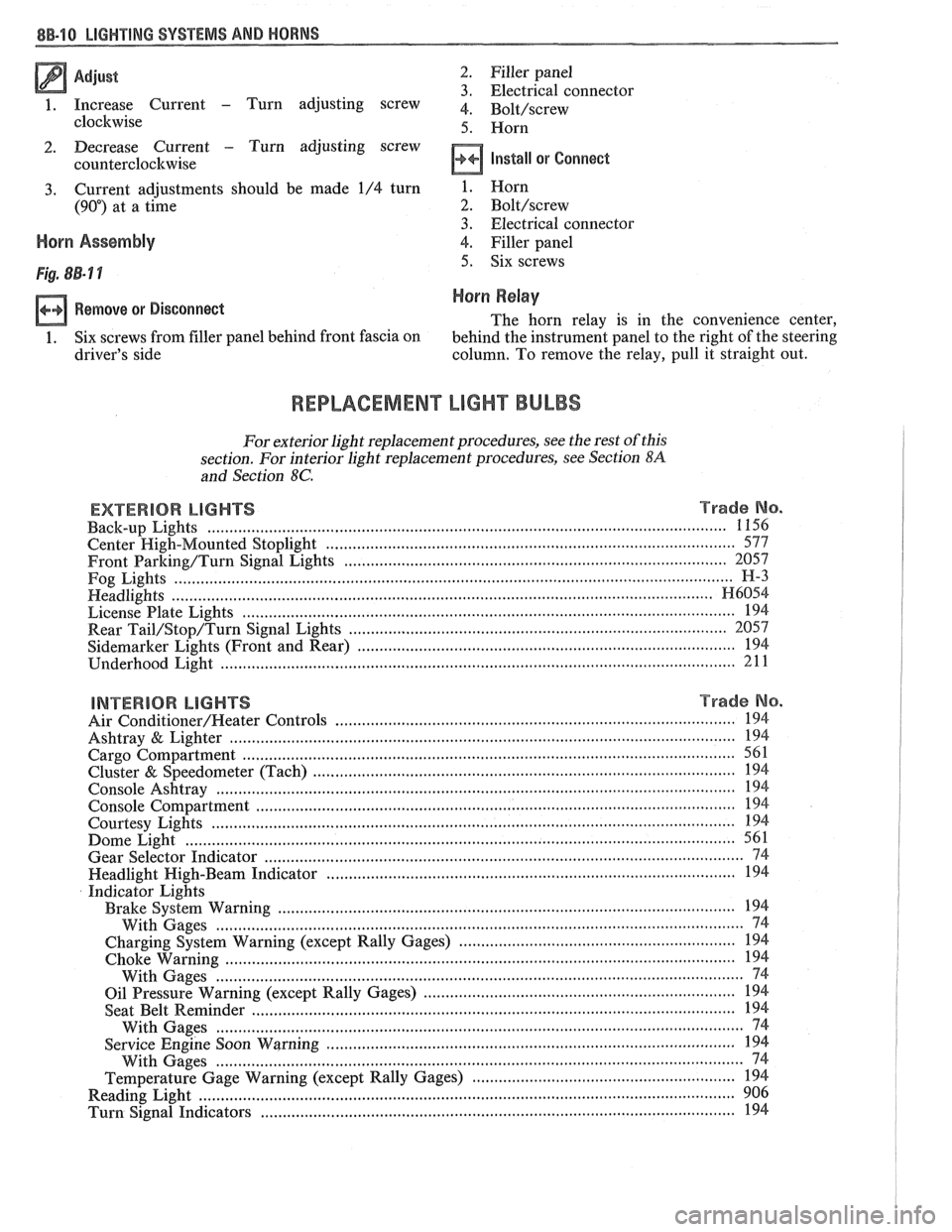
For exterior light replacement procedures. see the rest of this
section
. For interior light replacement procedures. see Section $A
and Section 8C .
EXTERIOR LIGHTS Trade No . ...................................................................................................................... Back-up Lights 1 156
Center
High-Mounted Stoplight ............................................................................................. 577
Front Barking/Turn Signal Eights ..................................................................................... 2057
Fog Lights
............................................................................................................................... H-3
Headlights ....................................................................................................................... H6054 ................................................................................................................ License Plate Lights 194
.................................................................................... Rear Tail/Stop/Turn Signal Lights 2057
Sidemarker Lights (Front and Rear) ...................................................................................... 194 ..................................................................................................................... Underhood Light 211
BNTERBOR LIGHTS Trade No .
......................................................................................... Air Conditioner/Heater Controls 194 .................................................................................................................. Ashtray & Lighter 194 .............................................................................................................. Cargo Compartment 561
................................................................................................ Cluster & Speedometer (Tach) 194 ..................................................................................................................... Console Ashtray 194 ............................................................................................................. Console Compartment 194
Courtesy Lights
..................................................................................................................... 194 ......................................................................................................................... Dome Light 561
Gear Selector Indicator
............................................................................................................ 74 .......................................................................................... Headlight High-Beam Indicator 194
Indicator Lights
..................................................................................................... Brake System Warning 194
With Gages
........................................................................................................................ 74
............................................................... Charging System Warning (except Rally Gages) 194 .................................................................................................................... Choke Warning
194
With Gages
........................................................................................................................ 74
...................................................................... Oil Pressure Warning (except Rally Gages) 194 ............................................................................................................ Seat Belt
Reminder 194
With Gages
.................................... ... ................................................................................. 74 ............................................................................................. Service Engine Soon Warning 194
With Gages
..................................................................................................................... 74 ............................................................ Temperature Gage Warning (except Rally Gages) 194
........................................................................................................................ Reading
Light 906 ............................................................................................................ Turn Signal Indicators 194
Page 1610 of 1825
LIGHTING SYSTEMS AND HORNS 8B-11
2-HORN LEADS 3-SIDE MARKER
4-HEADLAMP
%-TURN SIGNAL PARK LAMP
6-HEADLAMP MOTOR RELAY
7-HEADLAMP MOTOR JUMPER
8 -HEADLAMP ISOLATION RELAY
9- BRAKE PRESS. WARNING SW.
10-TO
SIDE MARKER
11-HORNS
12-TO
HEADLAMP
13-ENGINE HARNESSCONNECTOR
14-BULKHEAD CONNECTOR
15-CONNECTOR END CAP
16-HEADLAMP MOTOR ISOLATION RELAY
Fig. 8B-1 1 Forward Light Wiring
Page 1630 of 1825
WINDSHIELD WIPER SYSTEMS - F CARLINE 8E -3
WIPER-WASHER MOTOR
DIAGNOSTIC CHART
Fig. 4 Wiper-Washer Diagnostic Chart
ON-CAR SERVICE WIPER COVER REPLACEMENT
VVASHER PUMP REPLACEMENT Fig. 18
Fig. 21 Remove or Disconnect
Remove or Disconnect
1. Washer solvent
2. Brace
1. Cover screws
2. Wiper cover
Install sr Connect
3. Container screws (2) 1. New wiper cover
4. Electrical connectors and washer hose 2.
Cover screws
5. Washer pump motor from container Important
Install or Connect Always install cover assembly with wiper in
park position and drive pin in the open area
1. Washer pump motor to container of the cam.
2. Electrical connectors and washer hose
3. Container screws (2)
4. Brace
PARK SWITCH REPLACEMENT
Remove or Disconnect
Washer solvent 1. Wiper cover
Impo~ant important
@ Make sure new washer pump is pushed all
If motor is in park position (Fig. 18), operate
the way into the container gasket.
rnotor as required to remove pawl from relay
slot.
2. Park switch assembly
Page 1634 of 1825
WINDSHIELD WIPER SYSTEMS - F CARLllNE 8E -7
HARNESS
CONNECTOR
RECONNECT MOTOR
WITHOUT COVER. WHEN
MOTOR IS SWITCHED
FROM "LO" TO "OFF" IS
PARK SWITCH LATCH ARM
IN POSITION TO CATCH
REPLACE PARK
SWITCH OR
COVER ASSEMBLY
I (PULSEONLY). I
DRIVE
PAWL.
LATCH. REPLACE ROTATION
DRIVE PAWL
LATCH ARM (MUST BE
OUT OF WAY WHEN
GEAR IS REMOVED) RELAY
SLOT
Fig. 8 Diagnostic Procedure 5