1988 PONTIAC FIERO automatic transmission fluid
[x] Cancel search: automatic transmission fluidPage 786 of 1825
DRIVEABILITY AND EMlSSlONS 2.8L (VIN %I 6E3-C8-1
TRANSMISSION CONVERTER CLUTCH (KC) SYSTEM
AND MANUAL
TRANSMISSION SHIFT LIGHT
CONTENTS
GENERAL DESCRIPTION ................ C8-1 DIAGNOSIS ..........ee...ee....e.e. C8-1
PURPOSE ......................... C8-1 SHIFT LIGHT (MIT) DESCRIPTION ........ C8-1
OPERATION ....................... C8-1 DIAGNOSIS ....................... .. C8-1
ON-CAR SERVICE ...................*. C8-1
GENERAL DESCRIPTION
PURPOSE
The transmission converter clutch (TCC) svstem
uses a solenoid operated valve in the automatic
transmission to couple the engine flywheel to the
output shaft of the transmission thru the torque
converter. This reduces the slippage losses in the
converter, which increases fuel economy.
OPERATION
For the converter clutch to apply, two conditions
must be met:
o Internal transmission fluid pressure must be
correct. For information on internal transmission
operation, see Section
"7A". This section will cover
only the electrical operation of the TCC system.
@ The ECM grounds a switch internally to turn on a
solenoid in the transmission. This moves a check
ball, which will allow the converter clutch to
apply, if the hydraulic pressure is correct, as
described above.
The ECM controls the TCC apply solenoid by
looking at several sensors:
@ Speedo Buffer Sensor (also called vehicle speed
sensor
(VSS). Speed must be above a certain value
before the clutch can apply.
@ Coolant Temperature Sensor. Engine must be
warmed up before clutch can apply about
65OC
(149°F').
Throttle position sensor ('I'PS). After the
converter clutch applies, the
HCM uses the
information from the TPS to release thc clutch
when the car is accelerating or decelerating at a
certain rate.
@ 'I'he brake switch is also part of the 'I'CC circuit as
it will remove battery voltage to the 'KC solenoid
when the brake pedal is depressed.
@ Gear Select Switch. The 4th gear switch is used to
send a signal to the
ECM telling it when the
transmission is in 4th gear. The ECM uses this
information to vary the conditions under which
the clutch applies or releases.
IIowever, the
transmission does not have to be in fourth gear in
order for the ECM to turn the clutch on.
If the converter clutch is applied at all times. the
engine will stall immediately, just as in
u manual
transmission with the clutch applied.
If the converter clutch does not apply, fuel
ecomony
may be lower than expected. If the vehicle
speed sensor fails, the TCC will not apply. If the 4th
gear switch does not operate, the TCC may not apply
at the right time.
DIAGNOSIS
The diagnosis of the TCC system is covered in
CHART C-8
. If the ECM detects a problem in the
system,
a Code 24 should set. In this case see Code 24
CHART.
SHIFT LIGHT (MiT) DESCRIPTION
'The purpose of the shift light is to provide a
display which indicates the optimum fuel economy
point for up
shifling the manual transmission based
on engine speed
and load. 'I'he display is a lamp on the
instrument panel. Activation of the ECM driver turns
the lamp
on.
'I'he shift light circuit can he checlted using
CHAR?' C-8C.
ON-CAR SERVICE
@ See Section "8B" if the shift light bulb needs
replacement.
@ See Section "6E" to repair wiring problem.
@ See Section "6C" if ECM is to be replaced.
Page 787 of 1825
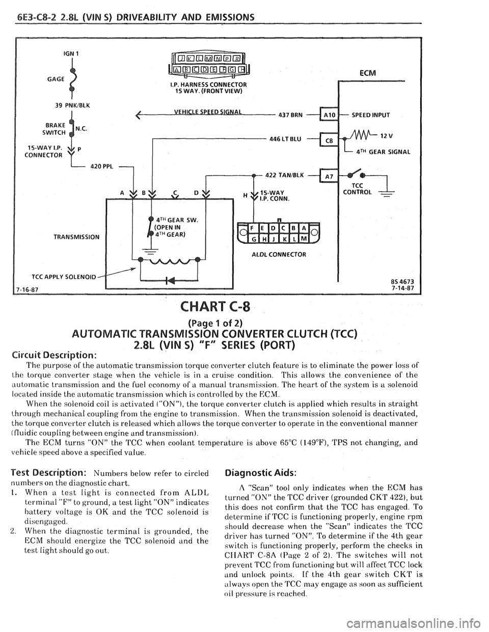
6E3-C8-2 2.8L (VIN S) DRIVEABILITY AND EMISSIONS
VEHICLE SPEED SIGNAL
SPEED INPUT
CONNECTOR
aTH GEAR SIGNAL
422 TAN/BLK
4TH GEAR SW.
TRANSMISSION
ALDL CONNECTOR
TCC APPLY SOLENOID
CHART C-8
(Page 1 of 2)
AUWBMATIC TRANSMISSION CONVERTER CLUTCH (TCC)
2.8L (VIN S) "F" SERIES (PORT)
Circuit Description:
The purpose of the automatic transmission torque converter clutch feature is to eliminate the power loss of
the torque converter stage when the vehicle is in a cruise condition. This allows the convenience of the
automatic transmission and the fuel economy of a manual transmission. The heart of the system is
a solenoid
located inside the automatic transmission which is controlled by the
ECM.
When the solenoid coil is activated ("ON"), the torque converter clutch is applied which results in straight
through mechanical coupling from the engine to transmission. When the transmission solenoid is deactivated,
the torque converter clutch is released which allows the torque converter to operate in the conventional manner
(fluidic coupling between engine and transmission).
The ECM turns
"ON" the 'KC when coolant temperature is above 65°C (14g°F), TPS not changing, and
vehicle speed above a specified value.
Test Description: Numbers below refer to circled Diagnostic Aids:
numbers on the diagnostic chart. A "Scan" tool only indicates when the ECM has 1. When a test light is connected from ALDL turned the TCC driver (grounded CKT 422), but terminal "F" to ground, a test light "ON" indicates
this does not confirm that the TCC has engaged. To battery voltage is OK and the TCC solenoid is
determine if TCC is functioning properly, engine rpm
disengaged.
should decrease when the "ScanJ' indicates the TCC
2. When the diagnostic terminal is grounded, the
driver has turned "ON". To determine if the 4th gear ECM energize the TCC "Ienoid and the switch is functioning properly, perform the checks in
test light should go out.
CIIART C-8A (Page 2 of 2). The switches will not
prevent TCC fi-om functioning but will affect TCC lock
and unlock points. If the 4th gear switch CKT is
always open the
TCC may engage as soon as sufficient
oil
pl.essure is reached.
Page 942 of 1825
DWlVEABlLlTV AND EMISSIONS 5.01, QVIN F) & 5.71 (VIN 8) 6E3-C8-1
TRANSMISSION CONVERTER CLUTCH (KC) SYSTEM
AND MANUAL "TRANSMISSION SHlFT LBGH"O"=Ob ONLY
CONTENTS
................ GENERAL DESCRIPTION C8-1 DIAGNOSIS ....................... .. C8-1
........ PURPOSE ......................... CS-1 SHIFT LIGHT (MIT) DESCRIPTION C8-1
....................... OPERATION C8-1 DIAGNOSIS ......................... CS-1
OM-CAR SERVICE ..................... C8-1
GENERAL DESCRIPTION
PURPOSE
The transmission converter clutch (TCC) system
uses
a solenoid operated valve in the automatic
transmission to couple the engine flywheel to the
output shaft of the transmission thru the torque
converter. This reduces the slippage losses in the
converter, which increases fuel economy.
OPERATION
For the converter clutch to apply, two conditions
must be met:
e Internal transmission fluid pressure must be
correct. For information on internal transmission
operation, see Section
"7A". This section will
cover only the electrical operation of the TCC
system.
@ The ECM grounds a switch internally to turn
"ON" a solenoid in the transmission. This moves a
check ball, which will allow the converter clutch
to apply, if the hydraulic pressure is correct, as
described above.
The ECM controls the TCC apply solenoid by
looking at several sensors:
@ Speedo Buffer Sensor (also called Vehicle Speed
Sensor
(VSS) Speed must be above a certain value
before the clutch can apply.
@ Coolant Temperature Sensor Engine must be
warmed
LIP before clutch can apply about 65" C
(149°F).
Throttle Position Sensor (TPS) After the
converter clutch applies, the ECM uses the
information
from the TPS to release the clutch
when the car is accelerating or decelerating at
a
certain rate.
The brake switch
is also part of the 'I'CC circuit as
it will remove battery voltage to the
'FCC solenoid
when the brake pedal is depressed.
@ Gear Select Switch The 4th gear switch is used to
send a signal to the ECM telling it when the
transmission is in 4th
gear
The ECM uses this information to vary the conditions
under which the clutch applies or releases. However,
the transmission does not have to be in fourth gear in
order for the ECM to turn the clutch "ON".
If the converter clutch is applied at all times, the
engine will stall immediately, just as in a manual
transmission with the clutch applied.
If the converter
clutch does not apply, fuel
ecomony may be lower than expected. If the vehicle
speed sensor fails, the TCC will not apply. If the 4th
gear switch does not operate, the TCC may not apply
at the right time.
DIAGNOSIS
The diagnosis of the TCC system is covered in
CHART C-$A. If the ECM detects a problem in the
system, a Code 24 should set. In this case, see Code 24
CHART.
SHIFT LIGHT (MR) DESCRIPTION
The purpose of the shift light is to provide a
display which indicates the optimum fuel economy
point for up shifting the manual transmission based
on engine speed and load. The display is
a lamp on the
instrument panel. Activation
of the ECM driver turns
the lamp "ON".
DIAGNOSIS
The shift light circuit can be checked using
CEIAR'I' C-8B.
ON-CAR SERVICE
See Section "8B" if the shift light bulb needs
replacement.
See Section
"GE" to repair wiring problem.
@ See Section "C- 1" if ECM is to be replaced.
Page 943 of 1825
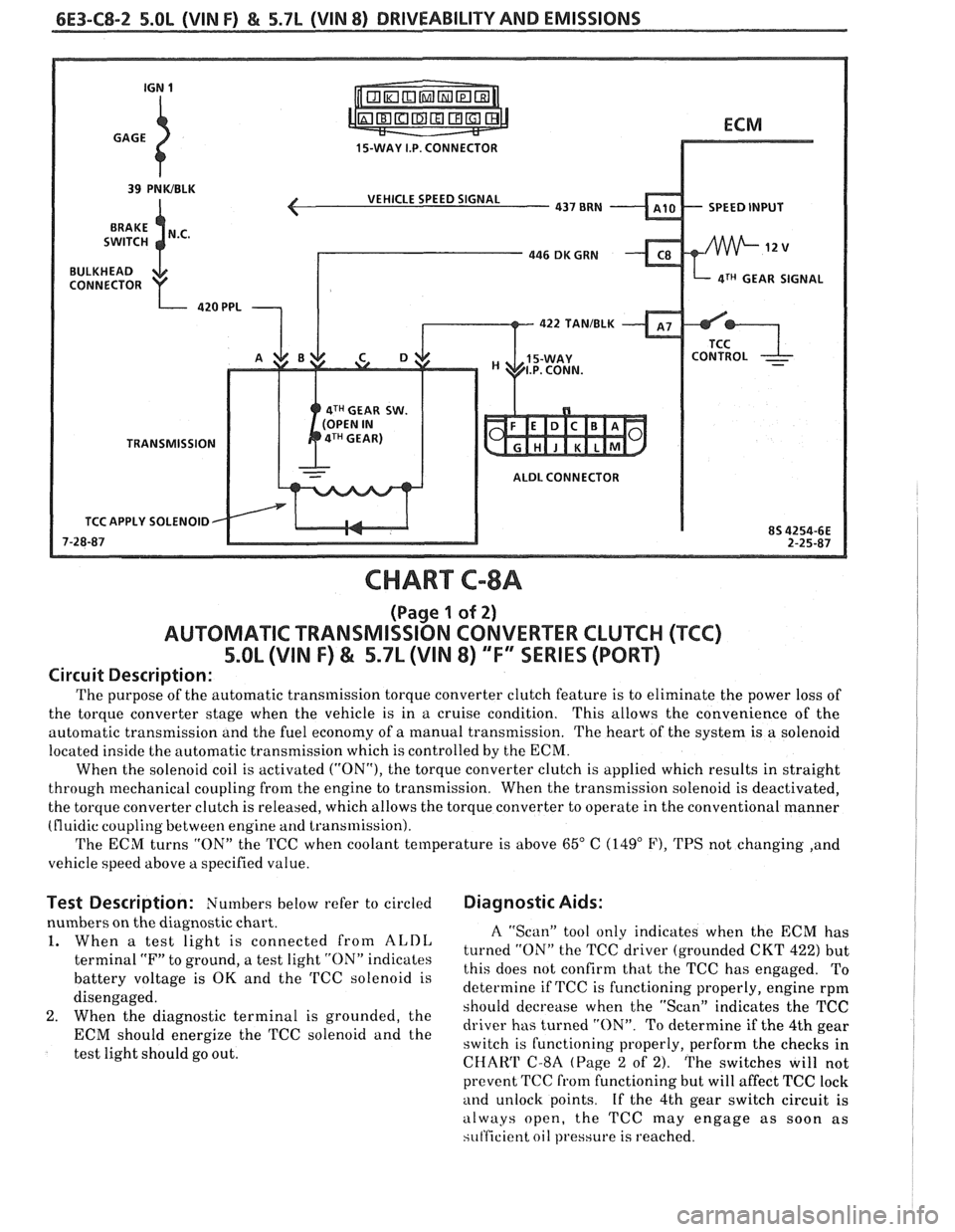
6E3-C8-2 5.OL (VIN F) & 5.7L (VIN 8) DRIVEABILITY AND EMISSIONS
15-WAY I.P. CONNECTOR
VEHICLE SPEED SIGNAL
SPEED INPUT
4TH GEAR SIGNAL
422
TANIBLK
4TH GEAR SW.
TRANSMISSION ALDL CONNECTOR
TCC APPLY SOLENOID
CHART C-8A
(Page 1 of 2)
AUTOMATIC TRANSMISSION CONVERTER CLUTCH (TCC)
5.OL (VIN F) & 5.7L (VIN 8) "F'" SERIES (PORT)
Circuit Description:
The purpose of the automatic transmission torque converter clutch feature is to eliminate the power loss of
the torque converter stage when the vehicle is in a cruise condition. This allows the convenience
of the
automatic transmission and the fuel economy of
a manual transmission. The heart of the system is a solenoid
located inside the automatic transmission which is controlled by the ECM.
When the solenoid coil is activated
("ON"), the torque converter clutch is applied which results in straight
through mechanical coupling from the engine to transmission. When the transmission solenoid is deactivated,
the torque converter clutch is released, which allows the torque converter to operate in the conventional manner
(fluidic coupling between engine
and transmission).
The ECM turns "ON" the TCC when coolant temperature is above
65" C (149" F), TPS not changing ,and
vehicle speed above
a specified value.
Test Description: Numbers below refer to circled Diagnostic Aids:
nbers on the diagnostic chart.
When
a test light is connected from ALDL
terminal "F" to ground, a test light "ON" indicates
battery voltage is
OK and the TCC solenoid is
disengaged.
When the diagnostic terminal is grounded, the
ECM should energize the TCC solenoid and the
test light should go out.
A "Scan" tool only indicates when the ECM has
turned "ON" the TCC driver (grounded CKT
422) but
this does not confirm that the TCC has engaged. To
determine if TCC is functioning properly, engine rpm
should decrease when the "Scan" indicates the TCC
driver has turned "ON". To determine if the 4th gear
switch is functioning properly, perform the checks in
CHAW C-8A (Page 2 of 2). The switches will not
prevent TCC
from functioning but will affect TCC lock
and unlock points. If the 4th gear switch circuit is
always open, the TCC may engage as soon as
si~t'ficient oil pressure is reached.
Page 1050 of 1825
TORQUE CONVERTER CLUTCH (TCC)
DIAGNOSIS
To properly diagnose the Torque Converter
Clutch (TCC) system, perform all electrical
testing first and then the hydraulic testing. Refer
to the Torque Converter Section
6E2-C8 for
additional information.
The TCC is applied by fluid pressure which is
controlled by a solenoid located inside the Automatic
Transmission assembly. The solenoid is energized or
released by making or breaking an electrical circuit
through a combination of switches and sensors.
TCC Electrical Diagnosis
e For electrical diagnosis of TCC, refer to the
specific vehicle section in Section
8A, Electrical
Diagnosis.
e For diagnosis of emission control related
components of TCC, Refer to the specific section
of
6E, Driveability and Emissions.
e For the diagnosis of TCC Hydraulic Controls,
refer to the Procedure and Wiring Diagrams
provided in this section.
Functional Check Procedure
rn Inspect
1. Install a tachometer
2. Operate the vehicle until proper operating
temperature is reached
3. Drive vehicle at 50-55 mph (80-88 Km/h) with
light throttle (road load)
4. Maintaining throttle lightly touch the brake
pedal and check for a slight bump when the TCC
releases and a slight increase in engine RPM.
5. Release the brake, slowly accelerate and check for
a re-apply of the converter clutch and a slight
decrease in engine RPM.
Preliminary Checking Procedure
The purpose of the preliminary checking
procedure is to isolate external (electrical) problems
from internal (electrical or mechanical) ones.
Important
e Use only a scale type ohmmeter. High impedance
type ohmmeters and those with a digital readout
will not work.
e An ALCL scanner may be used to verify the
electrical circuit. Remember, a completed circuit
does not indicate that the solenoid will apply.
e Do not bench test using an automotive type
battery. Accidentally crossed wires will damage
the internal diodes of the TCC solenoid.
HYDRAULIC DIAGNOSIS 700-R4-61
External Controls
rn Inspect
e Connect voltmeter between transmission
connector and ground.
e Turn key "ON"
e If 0 or low voltage is found, refer to Sections 6E
and 8A for electrical diagnosis.
e If 12 volts are present at the connector, refer to
the TCC hydraulic diagnosis.
TORQUE CONVERTER EVALUATION
Torque Converter Stator
The Torque Converter Stator roller clutch can
have one of two different type malfunctions:
A. Stator Assembly freewheels in both
directions.
B. Stator Assembly remains locked up at all
times.
Condition A-Poor Acceleration Low Speed
The vehicle tends to have poor acceleration from
a standstill. At speeds above 30-35 mph (50-55
km/h),
the car may act normal. If poor acceleration is noted,
it should first be determined that the exhaust system
is not blocked, the engine timing is correct and the
transmission is in first
(1st) gear when starting out.
If the engine freely accelerates to high
r.p.m. in
"NEUTRAL" (N), it can be assumed that the engine
and exhaust system are normal. Checking for poor
performance in "Drive" and Reverse will help
determine if the stator is freewheeling at all times.
Condition B-Poor Acceleration High Speed
Engine r.p.m. and car speed limited or restricted
at high speeds. Performance when accelerating from a
standstill is normal. Engine may over-heat. Visual
examination of the converter may reveal a blue color
from over-heating.
If the converter has been removed, the stator
roller clutch can be checked by inserting a finger into
the splined inner race of the roller clutch and trying to
turn the race in both directions. The inner race should
turn freely clockwise, but not turn or be very difficult
to turn counterclockwise.
The Converter Should Be Replaced If:
e Leaks externally, such as at the hub weld area.
e Converter has an imbalance which cannot be
corrected. (Refer to Converter Vibration Test
Procedure).
e Converter is contaminated with engine coolant
containing antifreeze.
The Converter Should Not Be Replaced If:
e The oil has an odor, is discolored, and there is no
evidence of metal or clutch facing particles.
e The threads in one or more of the three converter
bolt holes are damaged.
- Correct with thread insert. (Refer to Section
6A).
Page 1055 of 1825
700.R4.4 AUTOMATIC TRANSMISSION
TRANSMISSION DISASSEMBLY
General Service Information
e Teflon Oil Seal Rings
If any seal rings are damaged, cut, or do not
rotate freely in their groove be certain to check
the ring groove for debris, burrs, or damage.
s Thrust Washer Surfaces
The thrust washer and thrust bearing surfaces
may appear to be polished. This is a normal
condition and should not be considered damage.
Thoroughly clean the exterior of the
transmission.
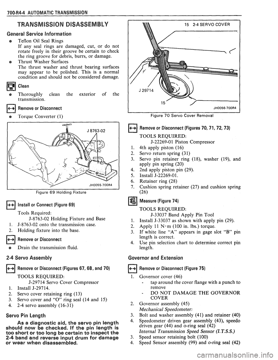
Remove or Disconnect
e 'Torque Converter (1)
I I Figure 69 Holding Fixture
Install or Connect (Figure 69)
Tools Required:
J-8763-02 Holding Fixture and Base
1. 5-8763-02 onto the transmission case.
2. Holding fixture into the base.
Remove or Disconnect
e Drain the transmission fluid.
2-4 Servo Assembly
Remove or Disconnect (Figures 67,68, and 70)
TOOLS REQUIRED:
J-297 14 Servo Cover Compressor
1. Install J-29714.
2. Servo cover retaining ring (13)
3. Servo cover and
"0" ring seal (14 and 15)
4. 2-4 servo assembly (16-31)
Servo Pin Length
As a diagnostic aid, the servo pin length
should now be checked.
If the pin length is
too short
or too long be certain to inspect the
2-4 band and reverse input drum for damage
or wear when disassembled.
15 2-4 SERVO COVER
Figure 70 Servo Cover Removal
Remove or Disconnect (Figures 70, 71,72,73)
TOOLS REQUIRED:
5-22269-01 Piston Compressor
1. 4th apply piston (16)
2. Servo return spring (31)
3. Servo pin
retainer ring
(18), washer (19), and
apply pin spring (20)
4, 2nd apply piston
pin (29).
5. Install J-22269-01.
6. Retainer ring
(28)
7. Cushion spring
retainer (27) and cushion spring
(26)
Measure (Figure 74)
TOOLS REQUIRED:
5-33037 Band Apply Pin Tool
1. Install 5-33037 as shown with apply pin (29).
2. Apply
1 1 N . m
(100 in. lbs.) torque.
3. If white line "A" appears in gage slot "B" pin
length is correct.
4. Use pin selection chart to determine correct pin
length.
Governor and Extension
Remove or Disconnect (Figure 75)
1. Governor cover (46)
- tap around the cover flange with a punch to
remove
- DO NOT DAMAGE THE GOVERNOR
COVER
2. Governor assembly (45)
Mechanical Speedometer:
3. Bolt and washer assembly (41) and retainer (40)
4. Speedometer driven gear assembly (43), speedo
driven gear (44) and o-ring seal (42)
Internal Transmission Speed Sensor
(I. T. S.S.)
3. Speed sensor retaining bolt (100)
4. Speed
Sensor assembly
(99) and o-ring seal (42)
Page 1069 of 1825
700-R4.18 AUTOMATIC TRANSMISSION
Case Assembly
a Clean
o Thoroughly with solvent
a Air dry
- do not wipe with cloth
Lo and Reverse Clutch Assembly
lnspect (Figure 101)
s Lo and reverse piston (695) for
- porosity or damage
- ring groove damage
e Piston seals (696) for nicks or cuts
o Spring assembly (694) for damage
Retainer ring (693) overstressed
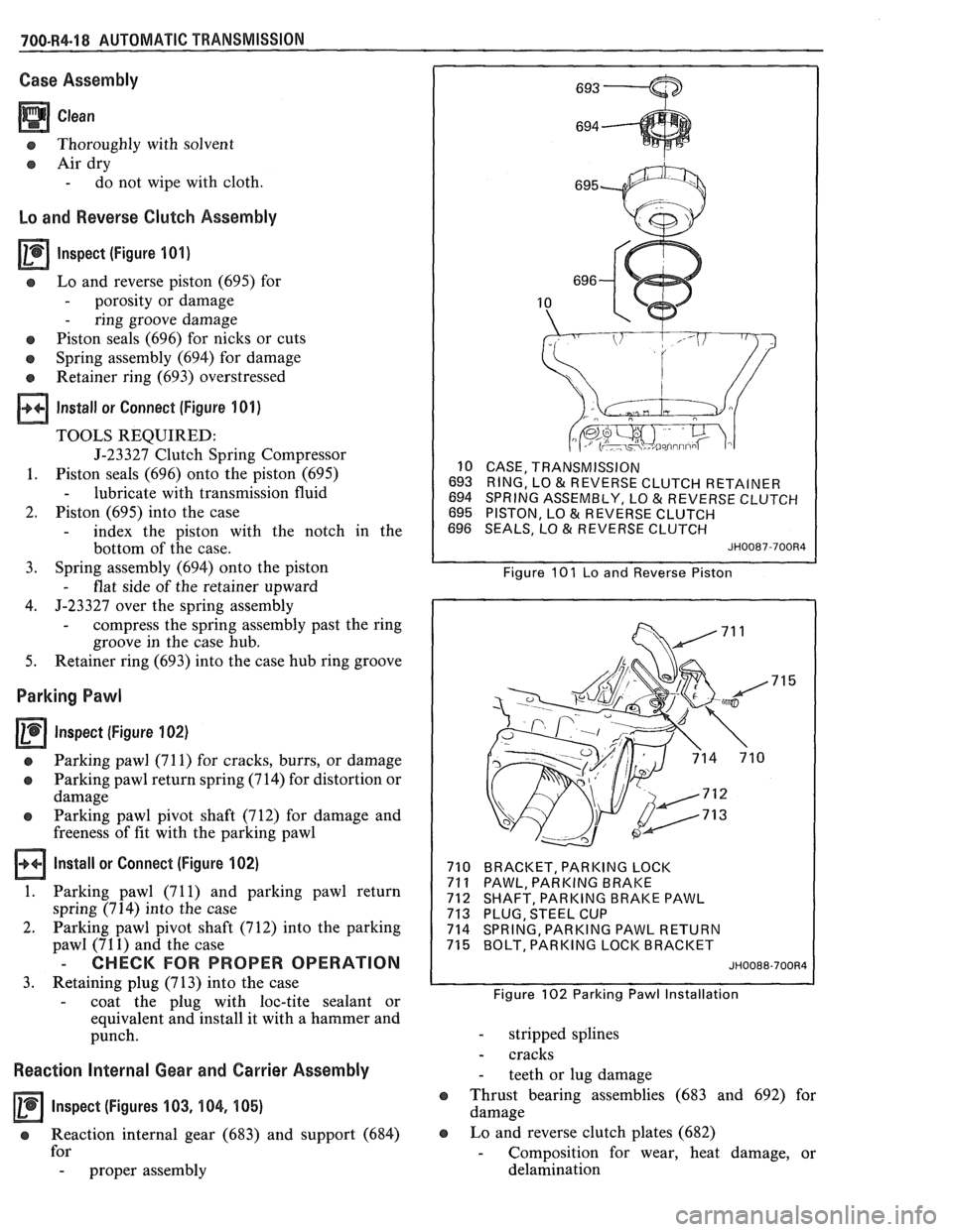
Install or Connect (Figure 101)
TOOLS REQUIRED:
J-23327 Clutch Spring Compressor
1. Piston seals (696) onto the piston (695)
- lubricate with transmission fluid
2. Piston (695) into the case
- index the piston with the notch in the
bottom of the case.
3. Spring
assembly (694) onto the piston
- flat side of the retainer upward
4. J-23327 over
the spring assembly
- compress the spring assembly past the ring
groove in the case hub.
5. Retainer ring (693) into the case hub ring groove
Parking Pawl
Inspect (Figure 102)
a Parking pawl (71 1) for cracks, burrs, or damage
o Parking pawl return spring (714) for distortion or
damage
e Parking pawl pivot shaft (712) for damage and
freeness of fit with the parking pawl
Install or Connect (Figure 102)
1. Parking pawl (71 1) and parking pawl return
spring (714) into the case
2. Parking pawl pivot shaft (712) into the parking
pawl (71
1) and the case
- CHECK FOR PROPER OPERATION
3. Retaining plug (713) into the case
- coat the plug with loc-tite sealant or
equivalent and install it with a hammer and
punch.
Reaction Internal Gear and Carrier Assembly
Inspect (Figures 103, 104, 105)
e Reaction internal gear (683) and support (684)
for
- proper assembly
10 CASE, TRANSMISSION
693 RING, LO
& REVERSE CLUTCH RETAINER
694 SPRING ASSEMBLY, LO & REVERSE CLUTCH
695 PISTON, LO & REVERSE CLUTCH
696 SEALS, LO & REVERSE CLUTCH
JH0087-700R4
Figure 101 Lo and Reverse Piston
710 BRACKET, PARKING LOCK
71
1 PAWL, PARKING BRAKE
712 SHAFT, PARKING BRAKE PAWL
713 PLUG, STEEL CUP
714 SPRING, PARKING PAWL RETURN
715 BOLT, PARKING LOCK BRACKET
JH0088-700R4
Figure 102 Parking Pawl Installation
- stripped splines
- cracks
- teeth or lug damage
e Thrust bearing assemblies (683 and 692) for
damage
e Lo and reverse clutch plates (682)
- Composition for wear, heat damage, or
delamination
Page 1079 of 1825
700-R4-28 AUTOMATIC TRANSMISSION
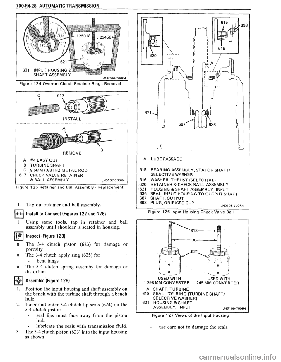
Figure 124 Overrun Clutch Retainer Ring - Removal
REMOVE
"
A #4 EASY OUT
B TURBINE SHAFT
C 9.5MM (318 IN.) METAL ROD
617 CHECK VALVE RETAINER
& BALL ASSEMBLY ~~0107-700~4
Figure 125 Retainer and Ball Assembly - Replacement
1. Tap out retainer and ball assembly.
Install or Connect (Figures 122 and 126)
1. Using same tools, tap in retainer and ball
assembly until shoulder is seated in housing.
Inspect (Figure 123)
e The 3-4 clutch piston (623) for damage or
porosity
e The 3-4 clutch apply ring (625) for
- bent tangs
The 3-4 clutch spring
assemby for damage or
distortion
Assemble (Figure 128)
1. Position the input housing and shaft assembly on
the bench with the turbine shaft through a bench
hole.
2. Inner and outer 3-4 clutch lip seals (624) on the
3-4 clutch piston
- seal lips must face away from the piston
hub.
- lubricate the seals with transmission fluid.
3. The 3-4 clutch piston (623) into the input housing
as shown
615 BEARlNGASSEMBLY,STATORSHAFT/
SELECTIVE WASHER
616 WASHER, THRUST (SELECTIVE)
620 RETAINER & CHECK BALL ASSEMBLY
621 HOUSING &SHAFT ASSEMBLY, INPUT
636 SEAL, INPUT HOUSING TO OUTPUT SHAFT 687 SHAFT, OUTPUT 698 PLUG, ORIFICED CUP JH0108-70084
Figure 126 lnput Housing Check Valve Ball
USED
WlTH MM CONVERTER
.621
USED WITH 245 MM CONVER
TER
A
SHAFT,TURBINE
618 SEAL, "0" RING (TURBINE SHAFT/ SELECTIVE WASHER) 621 HOUSING & SHAFT
ASSEMBLY, INPUT
JH0109-70084
Figure 127 Views of the lnput Housing
- use care not to damage the seals.