1988 PONTIAC FIERO automatic transmission fluid
[x] Cancel search: automatic transmission fluidPage 1080 of 1825
AUTOMATIC TRANSMISSION "/O-R4-29
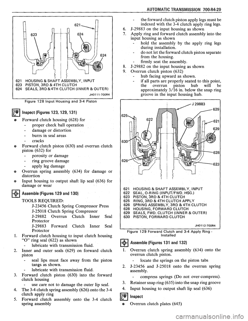
1 621 HOUSING & SHAFT
ASSEMBLY, INPUT
623 PISTON, 3RD
& 4TH CLUTCH
624 SEALS, 3RD &4TH CLUTCH (INNER & OUTE
Figure 128 Input Housing and 3-4 Piston
Inspect (figures 123, 129, 131)
Forward clutch housing (628) for
- proper check ball operation
- damage or distortion
- burrs in seal areas
- cracks
Forward clutch piston
(630) and overrun clutch
piston
(632) for
- porosity or damage
- ring groove damage
- apply leg damage
e Overrun spring assembly (634) for damage or
distortion
e Input housing to output shaft lip seal (636) for
damage or wear
Assemble (Figures 129 and 130)
TOOLS REQUIRED:
5-23456 Clutch Spring Compressor Press
5-25018 Clutch Spring Compressor
J-29882 Overrun Clutch Inner Seal
Protector
J-29883 Forward Clutch Inner Seal
Protector
1. Forward clutch housing to input clutch housing
"0" ring seal (622) as shown
- lubricate with transmission fluid.
2. Inner and outer seals (629) on forward clutch
piston
- seal lips must face away from the piston
tangs as shown.
- lubricate with transmission fluid.
3. Forward clutch piston (630) into the forward
clutch housing
- use care not to damage the outer lip seal.
4. The 3-4 clutch spring assembly (626) onto the 3-4
clutch apply ring
5. Forward clutch assembly onto the 3-4 clutch
spring assembly
- the forward clutch piston apply legs must be
indexed with the 3-4 clutch apply ring legs.
6.
J-29883 on the input housing as shown
7. Apply ring and forward clutch assembly into the
input housing as shown
- hold the assembly by the apply ring legs
during installation.
- do not let the forward clutch piston separate
from the housing.
- firmly seat the assembly.
8. J-29882 on the input housing as shown
9. Overrun clutch piston (632) - hub facing upward as shown. - if all parts are properly seated to this point,
the overrun piston hub will be
approximately
3/16 in. below the snap ring
groove in the input housing hub.
HOUSING 13( SHAFT ASSEMBLY, INPUT
SEAL, O-RING (INPUTIFWD. HSG.) PISTON, SRD & 4TH CLUTCH
RING, 3RD & 4TH CLUTCH APPLY
SPRING ASSEMBLY, 3RD & 4TH CLUTCH
HOUSING, FORWARD CLUTCH
SEALS, FWD. CLUTCH (INNER
& OUTER)
PISTON, FORWARD CLUTCH
JH0112-700R4
Figure 129 Forward Clutch and 3-4 Apply Ring - Installed
Assemble (Figures 1311 and 132)
1. Overrun clutch spring assembly (634) onto the
overrun clutch piston.
- locate the springs on the piston tabs
2. 5-23456 and J-25018 onto the overrun spring
assembly.
- compress springs (Do not over-compress).
3. Retainer snap ring (635) into the snap ring groove
4. Input housing to output shaft lip seal (636)
a Inspect
e Overrun clutch plates (645)
Page 1085 of 1825
700-R4.34 AUTOMATIC TRANSMISSION
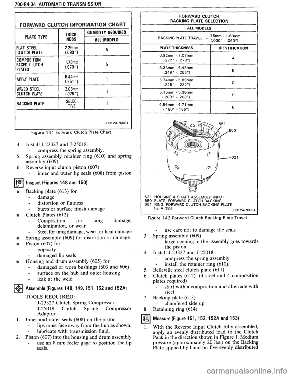
FORWARD CLUTCH INFORMAT ION CHART
THICK.
ALL MODELS
COMPOSITION
FACED CLUTCH
Figure 14 I Forward Clutch Plate Chart
4. Install J-23327 and J-25018.
- compress the spring assembly.
5. Spring assembly retainer ring (610) and spring
assembly (609)
6. Reverse
input clutch piston (607)
- inner and outer lip seals (608) from piston
Inspect (Figures 148 and 150)
e Backing plate (613) for
- damage
- distortion or flatness
- burrs or surface finish damage
Clutch Plates (612)
- Composition for tang damage,
delamination, or wear
- Steel for tang damage, wear, or heat damage
o Spring assembly (609) for distortion or damage
o Piston (607) for
- poposity
- damaged lip seals
o Housing and drum assembly (605) for
- damaged or worn bushings (603 and 606)
- surface on the hub and outer housing
- leak at the weld
Assemble (Figures 148, 1 49, 151, 152 and 152A)
TOOLS REQUIRED:
5-23327 Clutch Spring Compressor
J-25018 Clutch Spring Compressor
Adaptor
1. Inner and outer seals (608) on the piston
- lips must face away from the hub as shown.
- lubricate with transmission fluid.
2. Piston (607) into the housing and drum assembly
- use an 8 mm feeler gage to position the lip
seals.
FORWARD CLUTCH BACKING PLATE SELECTION
I ALL MODELS
BACKING PLATE TRAVEL =':,~~,--'~~$~
621 HOUSING & SHAFT ASSEMBLY, INPUT
650 PLATE, FORWARD CLUTCH BACKING
651 RING, FORWARD CLUTCH BACKING PLATE
RETAINER
JH0124-700R4
Figure 142 Forward Clutch Backing Plate Travel
- use care not to damage the seals.
3. Spring assembly (609)
- large opening in the assembly goes towards
the piston.
4. Install J-23327 and
J-25018.
- compress the spring assembly
- install the retainer ring (610).
5. Belleville steel
clutch plate (61 1)
6. Clutch
plates (612).
(4 steel and 4 composition
plates required)
- start with a composition and alternate with
steel
7. Backing plate (613)
- chamfered side up
8. Retaining ring (614)
Measure (Figure 151,152,152A and 153)
1. With the Reverse Input Clutch fully assembled,
apply an evenly distributed load to the Clutch
Pack in the direction shown in Figure
1. Medium
pressure (approximately 20 lbs.) on the Backing
Plate applied by hand on five evenly distributed
Page 1091 of 1825
700-W4-40 AUTOMATIC TRANSMISSION
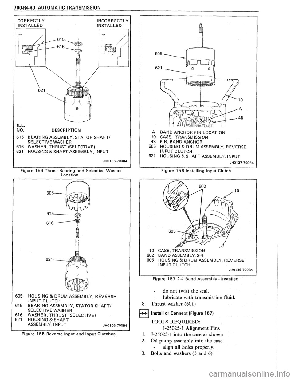
ILL.
NO. BESCW IPTIBN
615 BEARING ASSEMBLY, STATOR SHAFT/
SELECTIVE WASHER
616 WASHER, THRUST (SELECTIVE)
621 HOUSING & SHAFT ASSEMBLY, INPUT A
BAND ANCHOR PIN LOCATION
10 CASE, TRANSMISSION
48 PIN, BAND ANCHOR
605 HOUSING & DRUM ASSEMBLY, REVERSE
INPUT CLUTCH
621 HOUSING &SHAFT ASSEMBLY, INPUT
JH0137-700R4
Figure 154 Thrust Bearing and Selective Washer
Location Figure 156 Installirlg lnput
Clutch
605 HOUSING & DRUM ASSEMBLY, REVERSE I INPUT Cl-VTCH I
615 BEARING ASSEMBLY, STATOR SHAFT/ 1 SELECTIVE WASHER
616 WASHER THRUST (SELECTIVE)
Figure
155 Reverse lnput and lnput Clutches
CASE, TRANSMISSION BAND ASSEMBLY, 2-4
HOUSING & DRUM ASSEMBLY, REVERSE
I
INPUT CLUTCH JH0138-700R4 I
Figure 157 2-4 Band Assembly - Installed
- do not twist the seal.
- lubricate with transmission fluid.
8. Thrust washer (601)
Install or Connect (Figure 167)
TOOLS REQUIRED:
5-25025-1 Alignment Pins
1. 5-25025-1 into the case as shown
2.
Oil pump assembly into the case
- align all holes properly.
3. Bolts and washers (5 and 6)
Page 1100 of 1825
AUTOMATIC TRANSMISSION 700-R4-49
--
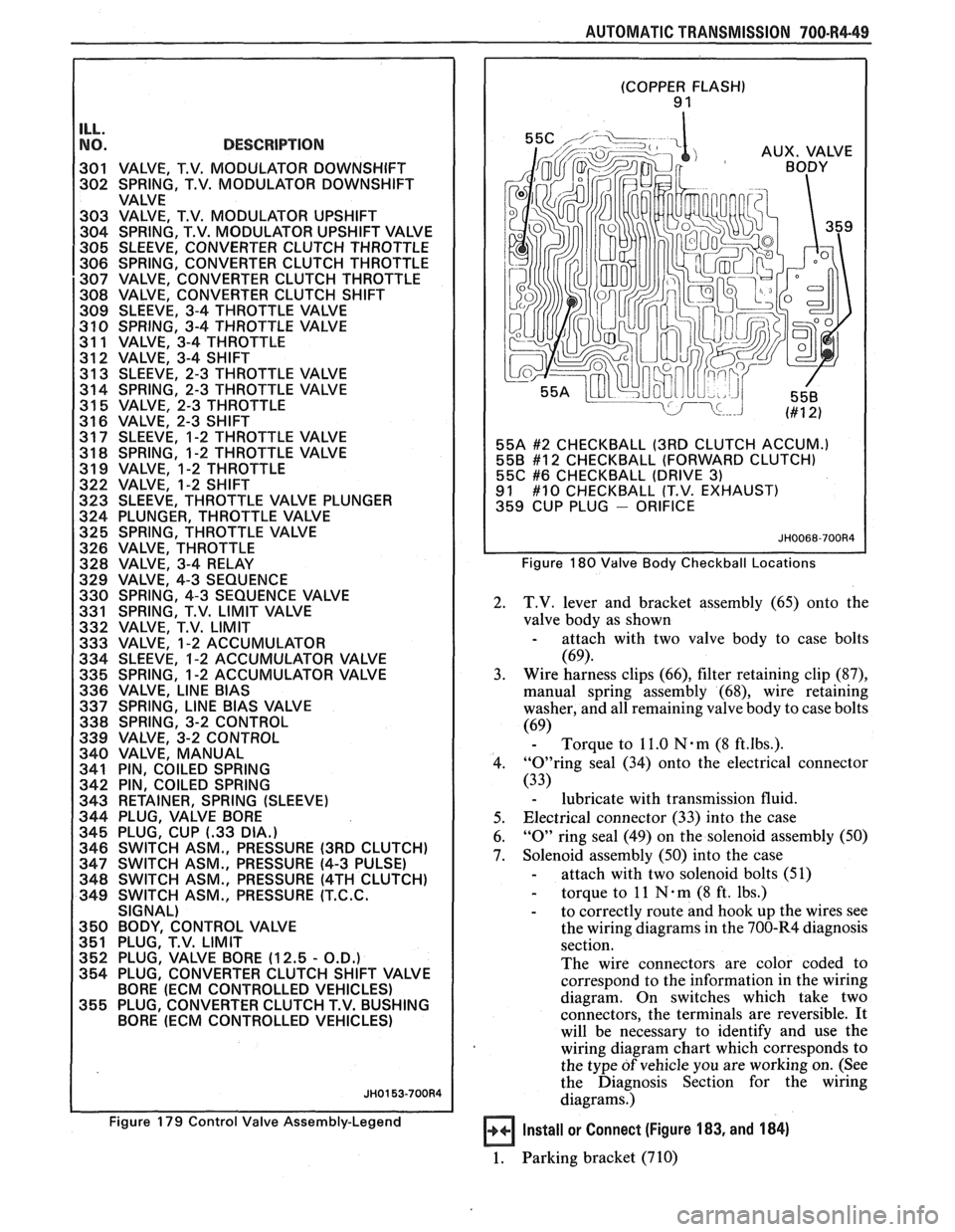
NO. DESCRIPTION I 301 VALVE, T.V. MODULATOR DOWNSHIFT
302 SPRING, T.V. MODULATOR DOWNSHIFT
VALVE
303 VALVE, T.V. MODULATOR UPSHIFT
304 SPRING, T.V. MODULATOR UPSHIFT VALVE
305 SLEEVE, CONVERTER CLUTCH THROTTLE
306 SPRING, CONVERTER CLUTCH THROTTLE
307 VALVE, CONVERTER CLUTCH THROTTLE
308 VALVE, CONVERTER CLUTCH SHlFT
309 SLEEVE, 3-4 THROTTLE VALVE
3 10 SPRING, 3-4 THROTTLE VALVE
31 1 VALVE, 3-4 THROTTLE
312 VALVE, 3-4 SHlFT
31 3 SLEEVE, 2-3 THROTTLE VALVE
314 SPRING, 2-3 THROTTLE VALVE
31
5 VALVE, 2-3 THROTTLE
31 6 VALVE, 2-3 SHlFT
31 7 SLEEVE, 1-2 THROTTLE VALVE
31
8 SPRING, 1-2 THROTTLE VALVE
31 9 VALVE, 1-2 THROTTLE
322 VALVE, 1-2 SHlFT
323 SLEEVE, THROTTLE VALVE PLUNGER
324 PLUNGER, THROTTLE VALVE
325 SPRING, THROTTLE VALVE
326 VALVE, THROTTLE
328 VALVE, 3-4 RELAY
329 VALVE, 4-3 SEQUENCE
330 SPRING, 4-3 SEQUENCE VALVE
331 SPRING, T.V.
LIMIT VALVE
332 VALVE, T.V.
LIMIT
333 VALVE, 1-2 ACCUMULATOR
334 SLEEVE, 1-2 ACCUMULATOR VALVE
335 SPRING, 1-2 ACCUMULATOR VALVE
336 VALVE,
LlNE BlAS
337 SPRING, LlNE BlAS VALVE
338 SPRING, 3-2 CONTROL
339 VALVE, 3-2 CONTROL
340 VALVE, MANUAL
341 PIN, COILED SPRING
342 PIN, COILED SPRING
343 RETAINER, SPRING (SLEEVE)
344 PLUG, VALVE BORE
345 PLUG, CUP
(-33 DIA.)
346 SWITCH ASM., PRESSURE (3RD CLUTCH)
347 SWITCH ASM., PRESSURE (4-3 PULSE)
348 SWITCH ASM., PRESSURE
(4TH CLUTCH)
349 SWITCH ASM., PRESSURE
(T.C.C.
SIGNAL)
350 BODY, CONTROL VALVE
351 PLUG, T.V. LIMIT
352 PLUG, VALVE BORE (12.5
- O.D.)
354 PLUG, CONVERTER CLUTCH SHlFT VALVE
BORE
(ECM CONTROLLED VEHICLES)
355 PLUG, CONVERTER CLUTCH T.V. BUSHING
BORE
(ECM CONTROLLED VEHICLES)
Figure 179 Control Valve Assembly-Legend
(COPPER FLASH) 9 1
55A
#2 CHECKBALL (3RD CLUTCH ACCUM.)
558 #12 CHECKBALL (FORWARD CLUTCH)
55C #6 CHECKBALL (DRIVE 3) 91 #10 CHECKBALL (T.V. EXHAUST)
359 CUP PLUG - ORIFICE
Figure 180 Valve Body Checkball Locations
2. T.V. lever and bracket assembly (65) onto the
valve body as shown
- attach with two valve body to case bolts
(69).
3. Wire harness
clips (66), filter retaining clip (87),
manual spring assembly (68), wire retaining
washer, and all remaining valve body to case bolts
(69) - Torque to 11.0 Nam (8 ft.lbs.).
4. "0"ring seal (34) onto the electrical connector
(33)
- lubricate with transmission fluid.
5. Electrical connector
(33) into the case
6.
"0" ring seal (49) on the solenoid assembly (50)
7. Solenoid assembly (50) into the case
- attach with two solenoid bolts (51)
- torque to 11 N . m (8 ft. lbs.)
- to correctly route and hook up the wires see
the wiring diagrams in the 700-R4 diagnosis
section.
The wire connectors are color coded to
correspond to the information in the wiring
diagram. On switches which take two
connectors, the terminals are reversible.
It
will be necessary to identify and use the
wiring diagram chart which corresponds to
the type
of vehicle you are working on. (See
the Diagnosis Section for the wiring
diagrams.)
Install or Connect (Figure 183, and 184)
1. Parking bracket (710)
Page 1101 of 1825
700.R4-50 AUTOMATIC TRANSMISSION
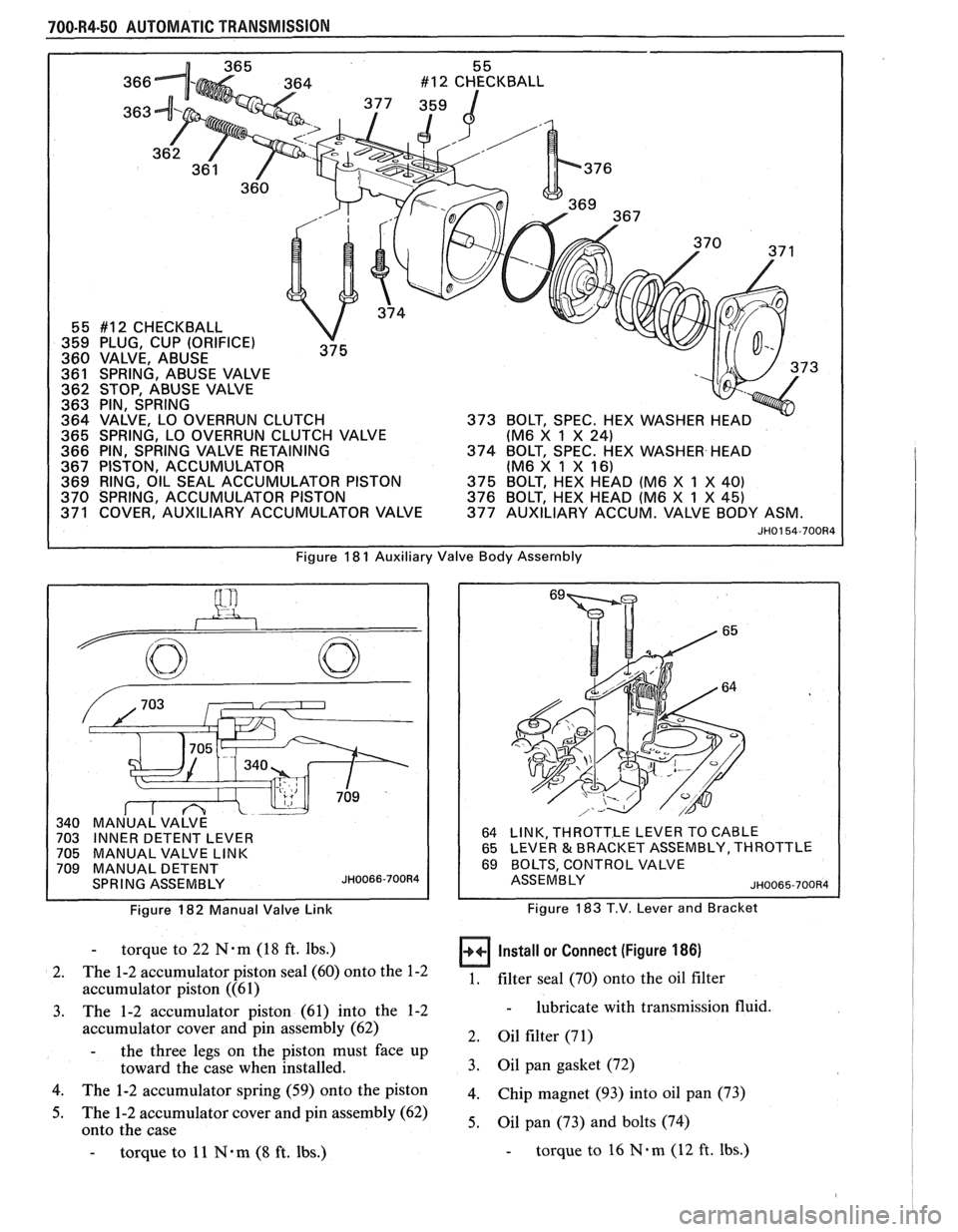
366
363
55 #12 CHECKBALL
359 PLUG, CUP (ORIFICE)
360 VALVE, ABUSE
361 SPRING, ABUSE VALVE 73
362 STOP, ABUSE VALVE
363 PIN, SPRING
364 VALVE, LO OVERRUN CLUTCH
365 SPRING, LO OVERRUN CLUTCH VALVE (M6
X
1 X 24)
366 PIN, SPRING VALVE RETAINING
374 BOLT, SPEC. HEX WASHER HEAD
367 PISTON, ACCUMULATOR (M6 X 1 X
16) 369 RING, OIL SEAL ACCUMULATOR PISTON
375 BOLT, HEX HEAD (M6 X 1 X 40)
370 SPRING, ACCUMULATOR PISTON 376 BOLT, HEX HEAD (M6 X 1 X 45) 371 COVER, AUXILIARY ACCUMULATOR VALVE 377 AUXILIARY ACCUM. VALVE BODY ASM.
JH0154-700R4
Figure 18 1 Auxiliary Valve Body Assernbly
Figure 182 Manual Valve Link
64 LINK, THROTTLE LEVER TO CABLE
65 LEVER & BRACKET ASSEMBLY, THROTTLE
69 BOLTS, CONTROL VALVE
ASSEMBLY ~H0065-700R4
Figure 183 T.V. Lever and Bracket
- torque to 22 N.m (18 ft. lbs.)
2. The
1-2 accumulator piston seal (60) onto the 1-2
accumulator piston ((61)
3. The 1-2 accumulator piston (61) into the 1-2
accumulator cover and pin assembly (62)
- the three legs on the piston must face up
toward the case when installed.
4. The 1-2 accumulator spring (59) onto the piston
5. The 1-2 accumulator cover and pin assembly (62)
onto the case
- torque to 11 N*m (8 ft. lbs.)
Install or Connect (Figure 186)
1. filter seal (70)
onto the oil filter
- lubricate with transmission fluid.
2. Oil filter (71)
3. Oil pan gasket (72)
4. Chip magnet (93) into oil pan (73)
5. Oil pan (73) and bolts (74)
- torque to 16 N.m (12 ft. Ibs.)
Page 1103 of 1825
700-R4-52 AUTOMATIC TRANSMISSION
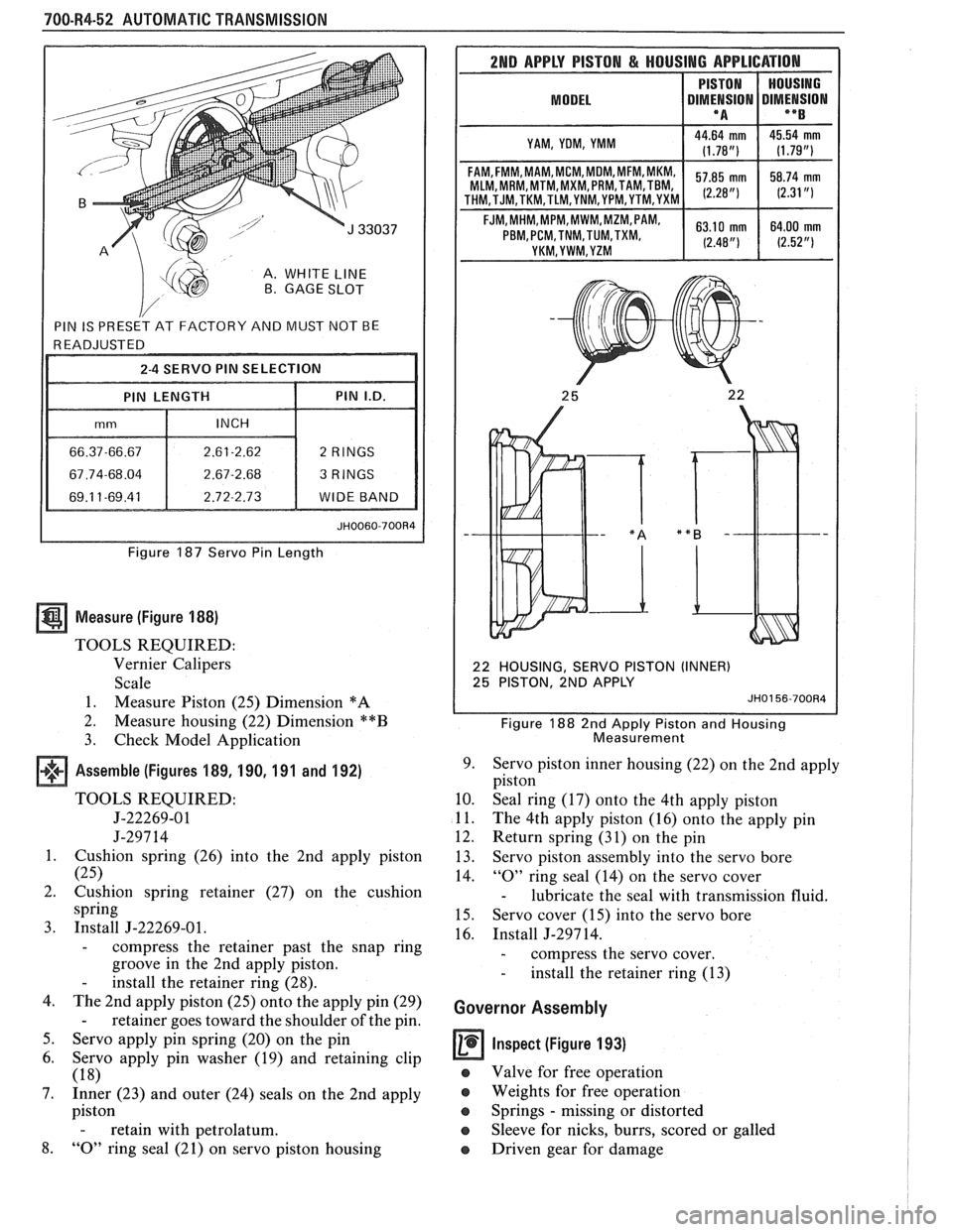
A. WHITE LINE B. GAGE SLOT
Figure 187 Servo Pin Length
Measure (Figure 188)
TOOLS REQUIRED:
Vernier Calipers
Scale
1. Measure Piston (25) Dimension
*A
2.
Measure housing (22) Dimension **B
3. Check Model Application
Assemble (Figures 189, 190, 191 and 192)
TOOLS REQUIRED:
5-22269-01
J-297 14
1. Cushion spring (26) into the 2nd apply piston
(25)
2. Cushion spring retainer (27) on the cushion
spring
3. Install J-22269-01.
- compress the retainer past the snap ring
groove in the 2nd apply piston.
- install the retainer ring (28).
4. The 2nd apply piston (25) onto the apply pin (29)
- retainer goes toward the shoulder of the pin.
5. Servo apply pin spring (20) on the pin
6. Servo apply pin washer (19) and retaining clip
(18)
7. Inner (23) and outer (24) seals on the 2nd apply
piston
- retain with petrolatum.
8. "0" ring seal (21) on servo piston housing
2ND APPLY PISTON & HOUSING APPLICATION
MODEL I DIMt!SION DIMENSION I **B I
I YAM, YOM, YMM I
MLM, MRM,MTM,MXM, PRM,TAM,TBM,
22 HOUSING, SERVO PISTON (INNER)
25 PISTON, 2ND APPLY
JH0156-700R4
Figure 188 2nd Apply Piston and Housing
Measurement
9. Servo piston inner housing (22) on the 2nd apply
piston
10. Seal ring (17) onto the 4th apply piston
11. The 4th apply piston (16) onto the apply pin
12. Return spring (31) on the pin
13. Servo piston assembly into the servo bore
14.
"0" ring seal (14) on the servo cover
- lubricate the seal with transmission fluid.
15. Servo cover (15) into the servo bore
16. Install J-297 14.
- compress the servo cover.
- install the retainer ring (13)
Governor Assembly
Inspect (Figure 193)
e Valve for free operation
e Weights for free operation
e Springs - missing or distorted
Sleeve for nicks, burrs, scored or galled
o Driven gear for damage
Page 1108 of 1825
AUTOMATIC TRANSMISSION 700-R4-57
If:
e
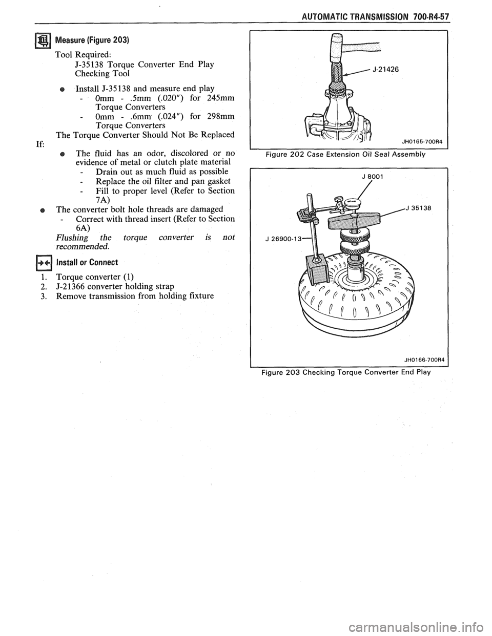
Measure (Figure 203)
Tool Required:
J-35138 Torque Converter End Play
Checking Tool
Install J-35 138 and measure end play
- Omm - .5mm (.02OU) for 245mm
Torque Converters
- Omm - .6mm (.024") for 298mm
Torque Converters
The Torque Converter Should Not Be Replaced
e The fluid has an odor, discolored or no
evidence of metal or clutch plate material
- Drain out as much fluid as possible
- Replace the oil filter and pan gasket
- Fill to proper level (Refer to Section
7A)
The converter bolt hole threads are damaged - Correct with thread insert (Refer to Section
6-4)
Flushing the torque converter is not
recommended.
Install or Connect
Torque converter (1)
J-2 1366 converter holding strap
Remove transmission from holding fixture
Figure 203 Checking Torque Converter End Play
Page 1114 of 1825
AUTOMATIC TRANSMISSION 700-R4-63
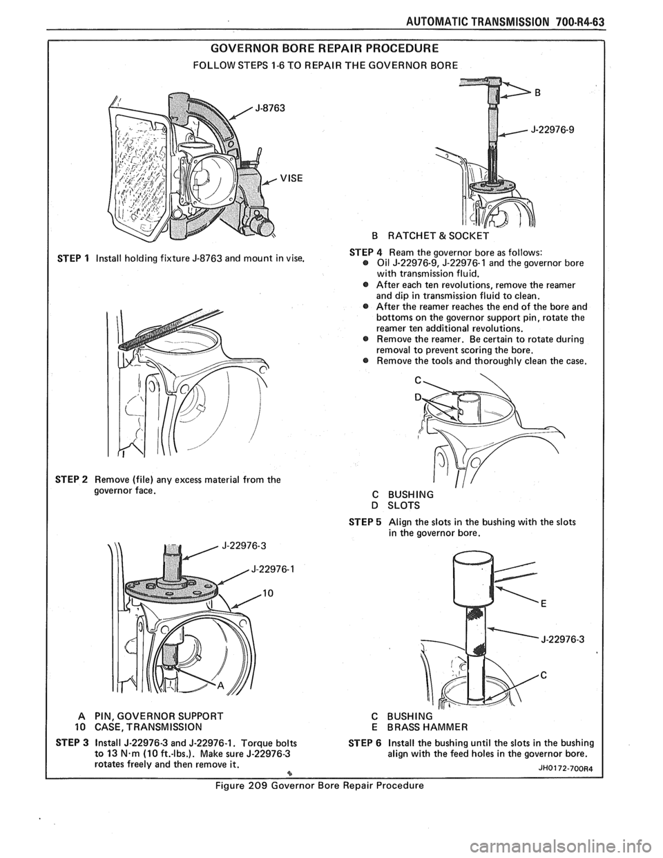
GOVERNOR BORE REPAIR PROCEDURE
FOLLOW STEPS 1-6 TO REPAIR THE GOVERNOR BORE
STEP
1 Install holding fixture J-8763 and mount in vise.
STEP
2 Remove (file) any excess material from the
governor face.
B RATCHET & SOCKET
STEP
4 Ream the governor bore as follows: @ Oil J-22976-9, J-22976-1 and the governor bore
with transmission fluid.
@ After each ten revolutions, remove the reamer
and dip in transmission fluid to clean.
@ After the reamer reaches the end of the bore and
bottoms on the governor support pin, rotate the
reamer ten additional revolutions.
Remove the reamer. Be certain to rotate during
removal to prevent scoring the bore.
Remove the tools and thoroughly clean the case.
C
C BUSHING
D SLOTS
STEP
5 Align the slots in the bushing with the slots
in the governor bore.
A PIN, GOVERNOR SUPPORT
10 CASE, TRANSMISSION
STEP
3 Install J-22976-3 and J-22976-1. Torque bolts
to 13 N.m (10 ft.-lbs.). Make sure J-22976-3
rotates freely and then remove it. *
C BUSHING
E BRASS HAMMER
STEP
6 Install the bushing until the slots in the bushing
align with the feed holes in the governor bore.
Figure 209 Governor Bore Repair Procedure