1988 PONTIAC FIERO ad blue
[x] Cancel search: ad bluePage 423 of 1825
88-12 ENGINE COOLING
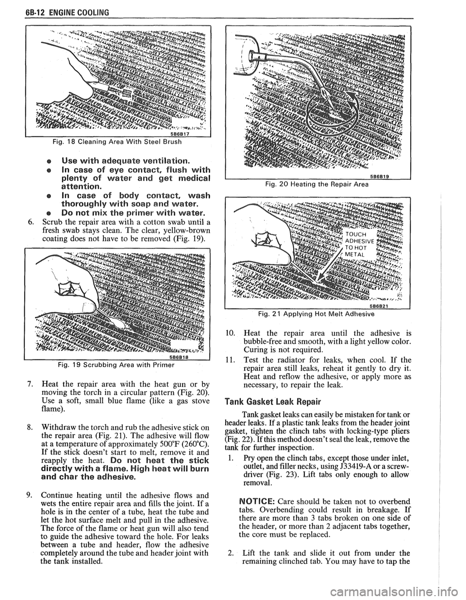
Fig. 18 Cleaning Area With Steel Brush
e Use with adequate ventilation.
In case of eye contact, flush with
plenty of water and get medical
attention.
In case of body
contact, wash
thoroughly with soap
and water.
Do not
mix the primer with water.
6. Scrub the repair area with a cotton swab until a
fresh swab stays clean. The clear, yellow-brown
coating does not have to be removed (Fig. 19).
Fig. 19 Scrubbing Area with Primer
7. Heat the repair area with the heat gun or by
moving the torch in a circular pattern (Fig. 20).
Use a soft, small blue flame (like a gas stove
flame).
8. Withdraw the torch and rub the adhesive stick on
the repair area (Fig. 21). The adhesive will flow
at a temperature of approximately 500°F (260°C).
If the stick doesn't start to melt, remove it and
reapply the heat.
Do not heat the stick
directly with
a flame. High heat will burn
and
char the adhesive.
9. Continue heating until the adhesive flows and
wets the entire repair area and fills the joint. If a
hole is in the center of a tube, heat the tube and
let the hot surface melt and pull in the adhesive.
The force of the flame or heat gun will also tend
to guide the adhesive toward the hole. For leaks
between a tube and header, flow the adhesive
completely around the tube and header joint with
the tank installed.
Fig. 20 Heating the Repair Area
I
Fig. 21 Applying Hot Melt Adhesive I
10. Heat the repair area until the adhesive is
bubble-free and smooth, with a light yellow color.
Curing is not required.
11. Test the radiator for leaks, when cool. If the
repair area still leaks, reheat it gently to dry it.
Heat and
reflow the adhesive, or apply more as
necessary, to repair the leak.
Tank Gasket beak Repair I 1
Tank gasket leaks can easily be mistaken for tank or
header leaks. If a plastic tank leaks from the header joint
gasket, tighten the clinch tabs with locking-type pliers
(Fig. 22). If this method doesn't seal the leak, remove the
tank for further inspection.
1. Pry open the clinch tabs, except those under inlet,
outlet, and filler necks, using
J33419-A or a screw-
driver (Fig.
23). Lift tabs only enough to allow
removal.
NOTICE: Care should be taken not to overbend
tabs. Overbending could result in breakage. If
there are more than
3 tabs broken on one side of
the header, or more than
2 adjacent tabs together,
the core must be replaced.
2. Lift the tank and slide it out from under the
remaining clinched tab. You may have to tap the
Page 472 of 1825
IGNITION SYSTEM 6B4-3
flash-over, which causes engine misfiring. Do not
mistake corona discharge for flash-over, or a shorted
insulator. Corona is a steady blue light appearing
around the insulator, just above the shell crimp. It is
the visible evidence of a high-tension field and has no
effect on ignition performance. Usually it can be
detected only in darkness. This discharge may repel
dust particles, leaving a clear ring on the insulator just
above the shell. This ring is sometimes mistakenly
regarded as evidence that combustion gases have blown
out between shell and insulator.
lgnition Switch
The mechanical switch is located in the steering
column on the right hand side just below the steering
wheel. The electrical switching portion of the assembly
is separate from the key and lock cylinder. However,
both are synchronized and work in conjunction with
each other through the action of the actuator rod
assembly.
For a complete explanation of the key and lock
cylinder, and the actuator rod assembly, see
STEERING, Section
38. See Section 8 for electrical
switching.
DIAGNOSIS
IGNITION SYSTEM
Spark Plugs
Worn or dirty plugs may give satisfactory
operation at idling speed, but at higher RPM they
frequently fail. Faulty plugs are indicated in a number
of ways: poor fuel economy, power loss, loss of speed,
hard starting and generally poor engine performance.
Spark plugs may also fail due to carbon fouling,
excessive gap, or a broken insulator. Fouled plugs may
be indicated by black carbon
deposits. The black deposits are usually the result of
slow-speed driving and short runs, where sufficient
engine operating temperature is seldom reached. Worn
pistons, rings, faulty ignition, over-rich carburetion
and spark plugs which are too cold will also result in
carbon deposits.
Excessive gap wear, on plugs of low mileage,
usually indicates the engine is operating at high speeds,
or loads that are consistently greater than normal, or
that a plug which is too hot is being used. Electrode
wear may also be the result of plug overheating,
causcd
by combustion gases leaking past the threads due to
insufficient torquing of the spark plug. Excessively lean
carburetion will also result in accelerated electrode
wear.
Broken insulators are usually the result of
improper installation, or carelessness when regapping
the plug. Broken upper insulators usually result from
a poor fitting wrench, or an outside blow. The cracked
insulator may not show up right away, but will as soon
as oil or moisture penetrates the crack. The crack is
usually just below the crimped part of shell and may
not be visible.
Broken lower insulators usually result from
carelessness when regapping and generally are visible.
This type of break may result from the plug operating
too "hot", which may happen in periods of high-speed
operation or under heavy loads. When regapping a
spark plug, always make the gap adjustment by
bending the ground (side) electrode. Spark plugs with
broken insulators should always be replaced.
HE1 Distributor
See Unit Repair for distributor disassembly, test
and reassembly of individual distributor components,
when the distributor is removed from the vehicle. See
On-Car Service for distributor removal and installation
and for component removal with distributor in car. See
Section 6E for
HE1 and EST diagnosis.
SERVICE PROCEDURES
IGNITION SYSTEM
Distributor Ignition
NOTICE: This procedure is generally true for
most carlines. Where procedure is different, or
where additional information is required, see
"ON-CAR SERVICE" for specific
carline.
HE1 DISTRIBUTOR
Service Precautions
1. When making compression checks, disconnect
the ignition switch feed wire at the distributor.
When disconnecting this connector,
do not use
a screwdriver or tool to release the locking tab, as
it may break.
2. No periodic lubrication is required. Engine oil
lubricates the lower bushing and an oil-filled
reservoir provides lubrication for the upper
bushing. 3.
The tachometer (TACH) terminal is next to the
ignition switch (BAT) connector on the
distributor cap.
NOTICE: The tachometer terminal must
NEVER be allowed to touch ground, as damage
to the module and/or ignition coil can result.
Some tachometers currently in use may NOT be
compatible with the High Energy Ignition System.
Consult the manufacturer of the tachometer if
questions arise.
4. Dwell adjustment is controlled by the module,
and cannot be adjusted.
5. The material used to construct the spark plug
cables is very soft. This cable will withstand more
heat and carry a higher voltage, but scuffing and
cutting become easier. The spark plug cables
must be routed correctly to prevent
chafing or
cutting. See Spark Plug Section. When removing
Page 1035 of 1825
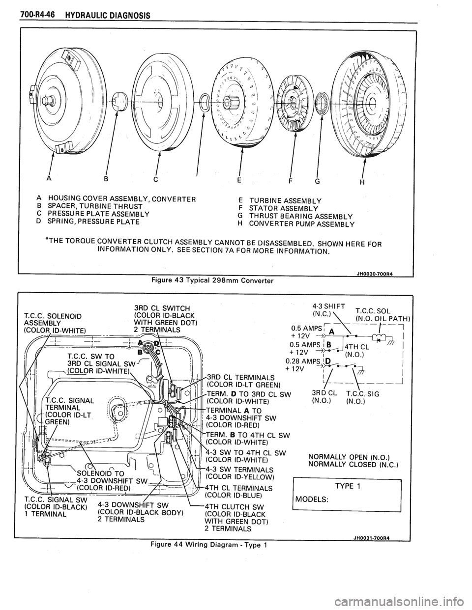
700.R4-46 HYDRAULIC DIAGNOSIS
A HOUSING COVER ASSEMBLY, CONVERTER E TURBINE ASSEMBLY
B SPACER, TURBINE THRUST
F STATOR ASSEMBLY
C PRESSURE PLATE ASSEMBLY
G THRUST BEARING ASSEMBLY
D SPRING, PRESSURE PLATE
H CONVERTER PUMP ASSEMBLY
"THE TORQUE CONVERTER CLUTCH ASSEMBLY CANNOT BE DISASSEMBLED. SHOWN HERE FOR
INFORMATION ONLY. SEE SECTION 7A FOR MORE INFORMATION.
3RD CL SWITCH
(COLOR ID-BLACK
4-3 SHIFT T.C.C. SOL
T.C.C. SOLENOID (N.C.)
ASSEMBLY WITH GREEN DOT)
I
+ 12v I
I
TERM. D TO 3RD CL SW 3RD CL T.C.C. SIG (COLOR ID-WHITE) (N.0.) (N.O.)
TERMINAL A TO
4-3 DOWNSHIFT SW
SW 4TH CL SW NORMALLY OPEN (N.O.) OLOR ID-WHITE)
NORMALLY CLOSED (N.C.) 4-3 SW TERMINALS
(COLOR ID-YELLOW)
4TH CL TERMINALS
(COLOR ID-BLUE)
MODELS: 4TH CLUTCH SW
(COLOR ID-BLACK
WlTH GREEN DOT) 2 TERMINALS
Page 1036 of 1825
MODELS:
HYDRAULIC DIAGNOSIS 70O-R4-47
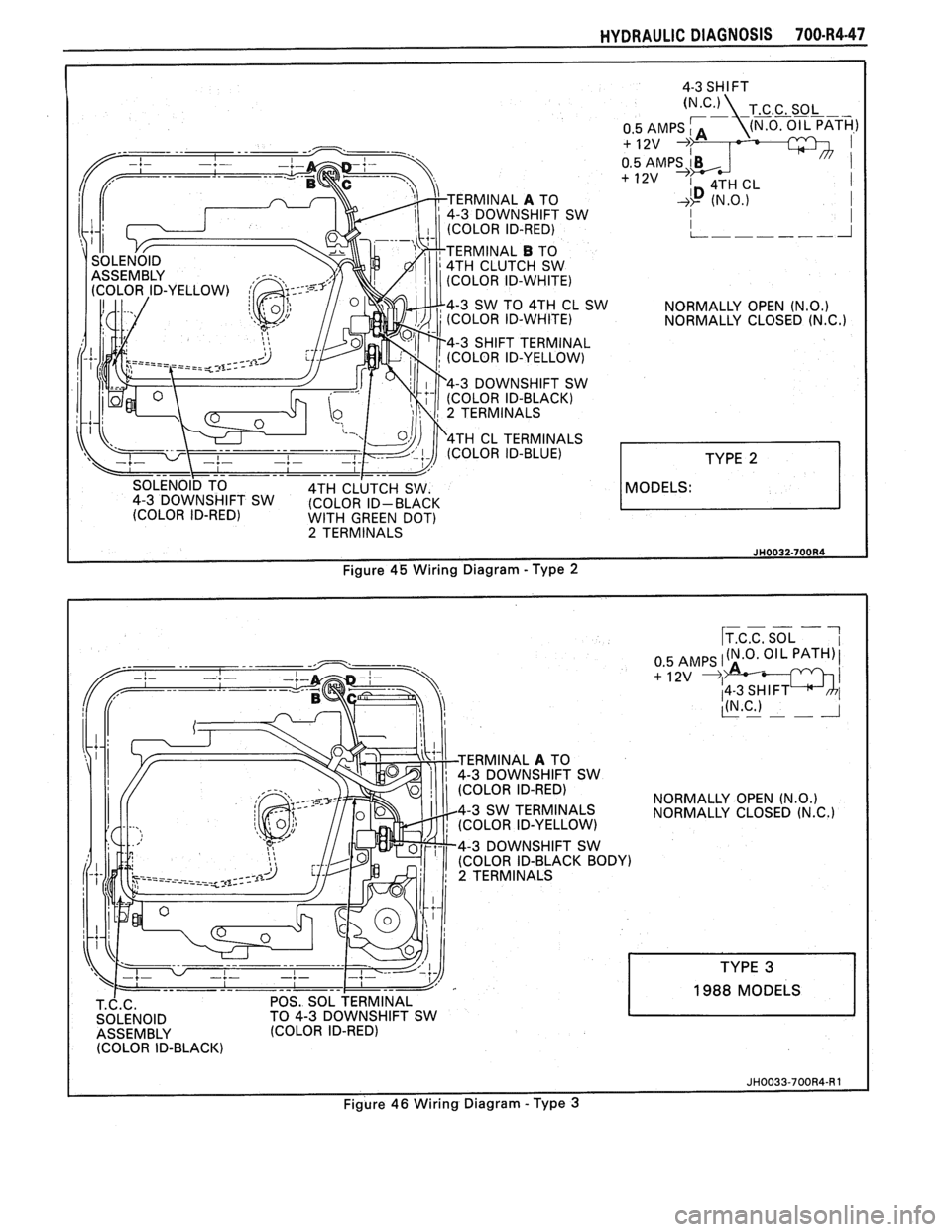
ERMINAL A TO
4-3 DOWNSHIFT SW
(COLOR ID-RED)
TERMINAL
B TO
4TH CLUTCH SW
(COLOR ID-WHITE)
4-3 SW TO 4TH CL SW
NORMALLY OPEN
(N.0.) (COLOR ID-WHITE) NORMALLY CLOSED (N.C.1
4-3 SHIFT TERMINAL
(COLOR ID-YELLOW)
4-3 DOWNSHIFT SW
(COLOR ID-BLACK)
2 TERMINALS
4TH CL TERMINALS
(COLOR ID-BLUE)
WITH GREEN DOT) 2 TERMINALS
3 DOWNSHIFT SW
NORMALLY OPEN
(N.0.) NORMALLY CLOSED (N.C.)
4-3 DOWNSHIFT SW
POS. SOL TERMINAL
TO 4-3 DOWNSHIFT SW
(COLOR ID-RED)
1988 MODELS
Figure
46 Wiring Diagram -Type 3
Page 1039 of 1825
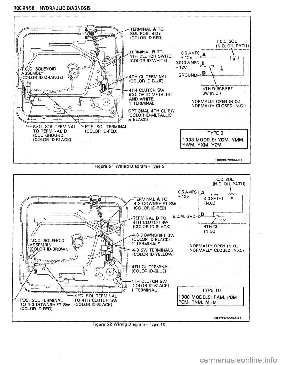
700-R4-50 HYDRAULIC DIAGNOSIS
TERMINAL A TO
SOL POS. SIDE (COLOR ID-RED)
T.C.C. SOL
(N.O. Ol L PATH)
TERMINAL
B TO
1 TERMINAL NORMALLY
OPEN (N.O.) NORMALLY CLOSED (N.C.)
NEG. SOL TERMINAL \POS. SOL TERMINAL
TO TERMINAL D (COLOR ID-RED)
(CCC GROUND)
(COLOR ID-BLACK)
Figure
5 1 Wiring Diagram - Type 9
TERMINAL A TO
4-3 DOWNSHIFT SW
(COLOR ID-RED)
TERMINAL
D TO E.C.M. 4TH CLUTCH SW
(COLOR ID-BLACK)
4-3 DOWNSHIFT SW
(COLOR ID-BLACK)
2 TERMINALS
NORMALLY OPEN (N.O.) 4-3 SW TERMINALS
NORMALLY CLOSED (N.C.) (COLOR ID-YELLOW)
4TH CL TERMINAL
(COLOR ID-BLUE)
4TH CLUTCH SW
(COLOR ID-BLACK)
1 TERMINAL
POS. SOL TERMINAL
TO 4-3 DOWNSHIFT SW
988 MODELS: PAM P
I (COLOR ID-RED)
I
Figure 52 Wiring Diagram - Type 10
Page 1040 of 1825
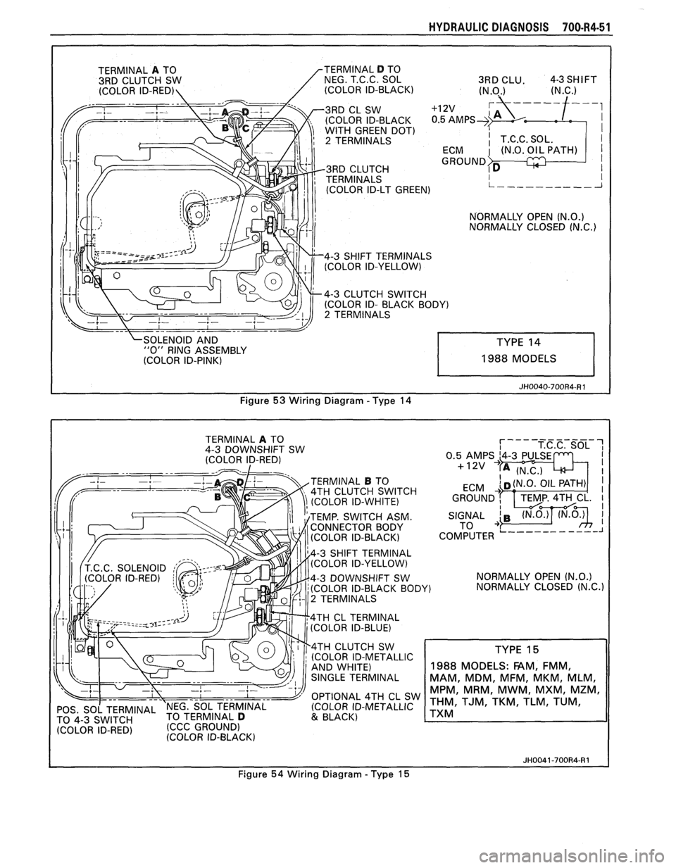
HYDRAULIC DIAGNOSIS 700-R4-51
OLEN NO ID AND "0" RING ASSEMBLY
(COLOR ID-PINK) 1988 MODELS
Figure
53 Wiring Diagram - Type 14
TERMINAL A TO
4-3 DOWNSHIFT SW
(COLOR ID-RED)
TERMINAL
B TO
4TH CLUTCH SWITCH
(COLOR ID-WHITE)
TEMP. SWITCH ASM.
CONNECTOR BODY
(COLOR ID-BLACK)
4-3 SHIFT TERMINAL
(COLOR ID-YELLOW)
4-3 DOWNSHIFT SW
(COLOR ID-BLACK BOD
2 TERMINALS
4TH
CL TERMINAL
(COLOR ID-BLUE)
4TH CLUTCH SW
(COLOR ID-METALLIC
OPTIONAL 4TH CL SW
POS, SO[ TERMINAL 'NEG. SOL TERMINAL (COLOR
ID-METALLIC
TO TERMINAL D 4-3 (CCC GROUND) & BLACK)
IDFRED' (COLOR ID-BLACK) NORMALLY
OPEN
(N.O.)
Y) NORMALLY CLOSED (N.C.)
TYPE 15
1988
MODELS: FAM, FMM,
MAM, MDM, MFM, MKM, MLM,
MPM, MRM, MWM, MXM, MZM,
THM, TJM, TKM, TLM, TUM,
TXM
JH0041-700R4-R1
Figure 54 Wiring Diagram - Type 15
Page 1050 of 1825
TORQUE CONVERTER CLUTCH (TCC)
DIAGNOSIS
To properly diagnose the Torque Converter
Clutch (TCC) system, perform all electrical
testing first and then the hydraulic testing. Refer
to the Torque Converter Section
6E2-C8 for
additional information.
The TCC is applied by fluid pressure which is
controlled by a solenoid located inside the Automatic
Transmission assembly. The solenoid is energized or
released by making or breaking an electrical circuit
through a combination of switches and sensors.
TCC Electrical Diagnosis
e For electrical diagnosis of TCC, refer to the
specific vehicle section in Section
8A, Electrical
Diagnosis.
e For diagnosis of emission control related
components of TCC, Refer to the specific section
of
6E, Driveability and Emissions.
e For the diagnosis of TCC Hydraulic Controls,
refer to the Procedure and Wiring Diagrams
provided in this section.
Functional Check Procedure
rn Inspect
1. Install a tachometer
2. Operate the vehicle until proper operating
temperature is reached
3. Drive vehicle at 50-55 mph (80-88 Km/h) with
light throttle (road load)
4. Maintaining throttle lightly touch the brake
pedal and check for a slight bump when the TCC
releases and a slight increase in engine RPM.
5. Release the brake, slowly accelerate and check for
a re-apply of the converter clutch and a slight
decrease in engine RPM.
Preliminary Checking Procedure
The purpose of the preliminary checking
procedure is to isolate external (electrical) problems
from internal (electrical or mechanical) ones.
Important
e Use only a scale type ohmmeter. High impedance
type ohmmeters and those with a digital readout
will not work.
e An ALCL scanner may be used to verify the
electrical circuit. Remember, a completed circuit
does not indicate that the solenoid will apply.
e Do not bench test using an automotive type
battery. Accidentally crossed wires will damage
the internal diodes of the TCC solenoid.
HYDRAULIC DIAGNOSIS 700-R4-61
External Controls
rn Inspect
e Connect voltmeter between transmission
connector and ground.
e Turn key "ON"
e If 0 or low voltage is found, refer to Sections 6E
and 8A for electrical diagnosis.
e If 12 volts are present at the connector, refer to
the TCC hydraulic diagnosis.
TORQUE CONVERTER EVALUATION
Torque Converter Stator
The Torque Converter Stator roller clutch can
have one of two different type malfunctions:
A. Stator Assembly freewheels in both
directions.
B. Stator Assembly remains locked up at all
times.
Condition A-Poor Acceleration Low Speed
The vehicle tends to have poor acceleration from
a standstill. At speeds above 30-35 mph (50-55
km/h),
the car may act normal. If poor acceleration is noted,
it should first be determined that the exhaust system
is not blocked, the engine timing is correct and the
transmission is in first
(1st) gear when starting out.
If the engine freely accelerates to high
r.p.m. in
"NEUTRAL" (N), it can be assumed that the engine
and exhaust system are normal. Checking for poor
performance in "Drive" and Reverse will help
determine if the stator is freewheeling at all times.
Condition B-Poor Acceleration High Speed
Engine r.p.m. and car speed limited or restricted
at high speeds. Performance when accelerating from a
standstill is normal. Engine may over-heat. Visual
examination of the converter may reveal a blue color
from over-heating.
If the converter has been removed, the stator
roller clutch can be checked by inserting a finger into
the splined inner race of the roller clutch and trying to
turn the race in both directions. The inner race should
turn freely clockwise, but not turn or be very difficult
to turn counterclockwise.
The Converter Should Be Replaced If:
e Leaks externally, such as at the hub weld area.
e Converter has an imbalance which cannot be
corrected. (Refer to Converter Vibration Test
Procedure).
e Converter is contaminated with engine coolant
containing antifreeze.
The Converter Should Not Be Replaced If:
e The oil has an odor, is discolored, and there is no
evidence of metal or clutch facing particles.
e The threads in one or more of the three converter
bolt holes are damaged.
- Correct with thread insert. (Refer to Section
6A).
Page 1187 of 1825
REPAIR PROCEDURES 0) B
ELECTRICAL REPAIRS
This section provides instruction in the fol-
lowing repairs:
- Circuit Protection
- Typical Electrical Repairs
- Splicing Copper Wire
- Splicing Aluminum \l.ire
- Splicing Txisted Shielded Cable
- Repairing Connectors (Except Weather
Pack
V and
- Repairing breather I'ack * (Environmen-
tal) Connectors
Note: After any electrical repair is made, always
test the circuit by operating the devices in the
circuit. This confirms not only that the repair is
correct, but also that the cause of the complaint
was correctly identified.
CIRCUIT PROTECTION
All electrical circuits are protected against
excessive loads which might occur because of
shorts or overloads in the wiring system. Such
protection is
prolrided by a fuse. circuit
breaker. or fusible link.
Fuses
The most common method of automotive
wiring circuit protection is the fuse. Whenever
there is an excessive amount of current flow-
ing through a circuit the fusible element will
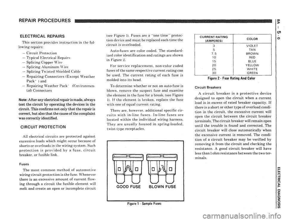
melt and create an open or incomplete circuit (see
Figure
1). Fuses are a "one time" protec-
tion device and must be replaced each time the
circuit is overloaded.
Auto-fuses are color coded. The standard-
ized color identification and ratings are shown
in Figure
2.
For senrice replacement. non-color coded
fuses of the same respective current rating can
be used. The current rating of each fuse is
molded into its head.
To determine whether or not an auto-fuse is
blown, remove the suspect fuse and examine
the element in the fuse for a break, (see Figure
1). If the element is broken, replace the fuse
with one of equal current rating.
There are, however. additional specific cir-
cuits with in-line fuses. In-line fuses are
located within the individual wiring harness.
They are usually housed in spring-loaded,
twist-type receptacles.
GOOD FUSE BLOWN FUSE
Figure 1 - Sample Fuses Figure
2 - Fuse Rating And Galor
CURRENT
RATING
(AMPERES)
3
5
7.5
10
15
20
2
5
30
Circuit Breakers
COLOR
VIOLET
TA N
BROWN RED
BLUE
YELLOW
WHITE
GREEN
A circuit breaker is a protective device
designed to open the circuit when a current
load is in excess of rated breaker capacity. If
there is a short or other type of overload condi-
tion in the circuit, the excessive current will
open the circuit between the circuit breaker
terminals. The circuit breaker will remain open
until the trouble is found and corrected. The
circuit breaker will close automatically when
the excessive current is removed. The condi-
tion of a circuit breaker may be verified by
removing it from the circuit and checking the
resistance.
A good circuit breaker will have
less than
1 ohm resistance between the two ter-
minals.