1987 SUZUKI GRAND VITARA ignition
[x] Cancel search: ignitionPage 220 of 962
![SUZUKI GRAND VITARA 1987 Service Repair Manual [Checking vacuum advancer]
Remove distributor cap.
Disconnect vacuum hose from vacuum hose 3
way joint, and connect vacuum pump gauge
(0991747910) to its hose. Apply vacuum (ab-
out 400 mmHg). And the SUZUKI GRAND VITARA 1987 Service Repair Manual [Checking vacuum advancer]
Remove distributor cap.
Disconnect vacuum hose from vacuum hose 3
way joint, and connect vacuum pump gauge
(0991747910) to its hose. Apply vacuum (ab-
out 400 mmHg). And the](/manual-img/20/57437/w960_57437-219.png)
[Checking vacuum advancer]
Remove distributor cap.
Disconnect vacuum hose from vacuum hose 3
way joint, and connect vacuum pump gauge
(0991747910) to its hose. Apply vacuum (ab-
out 400 mmHg). And then with pump stopped,
check to ensure that vacuum pump gauge
indicator remains at the same level, and release
it. Check that generator base plate with gene-
rator moves smoothly. If plate does not move
smoothly, replace defective parts.
Fig. 8-24
1. Distributor drive gear
2. Camshaft3. Cylinder head
Fig. 8-23
@I Vacuum pump gauge (a991 7-47910)
1. Generator base plate
2. Vacuum controller
Distributor Drive Gear
NOTE:
When removing distributor gear case from cylin-
der head, engine oil in cylinder head may come
out. So place waste or receiver under gear case
when removing.
Inspect drive gear for wear.
Worn gear is likely to disturb ignition timing
and therefore must be replaced.
Replacing worn-down drive gear is not enough.
Inspect driven gear (a part of the distributor
assembly), too, and replace it if badly worn
down.
[Important reminders for removal and installa-
tion]
Before removing drive gear from camshaft,
scribe a match mark on this shaft to root
center line of drive gear as shown in Fig.
B-25 and, when mounting replacement drive
gear, refer to this mark.
When pressing replacement drive gear onto
camshaft, be sure to position gear angularly
as shown in Fig. B-25. (align mark on Cam-
shaft scribed in removal with root center of
drive gear)
NOTE:
There is no need to discriminate between two
end faces of drive gear.
Distributor side view
1. Drive gear
2. Camshaft
3. Center line of
45mmhole
4. Center line ofroot5. @5mm hole(Provided on pulleyside of camshaft)
6. Scribed matchmark
7. 5O
Fig. 8-25
l About 30 cc(1.01/l .05 US/Imp 02) of
engine oil must be fed into distributor gear
case after servicing this case, that is, removing
and putting it back. Be sure to add this much
oil before starting engine for the first time
after servicing.
8-11
Page 221 of 962
8-3. IMPORTANT REMINDERS FOR
INSTALLATIONDistributor
When re-installing distributor, be sure to insertit into distributor gear case in the following
sequence:
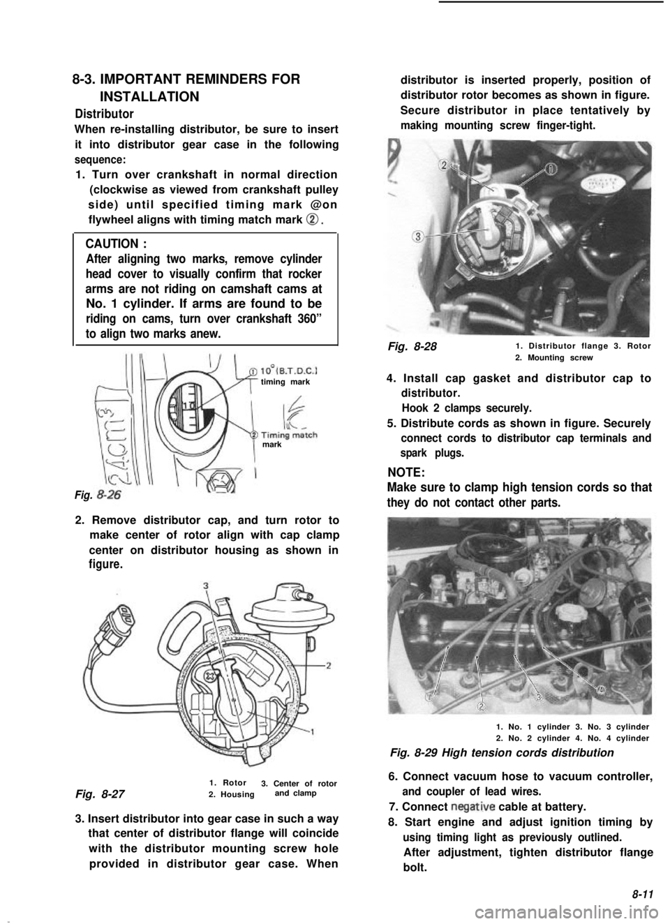
1. Turn over crankshaft in normal direction (clockwise as viewed from crankshaft pulley
side) until specified timing mark @on flywheel aligns with timing match mark
0.
CAUTION :
After aligning two marks, remove cylinder
head cover to visually confirm that rocker
arms are not riding on camshaft cams at
No. 1 cylinder. If arms are found to be
riding on cams, turn over crankshaft 360”
to align two marks anew.
lO’(B.T.D.C.1timing mark
mark
Fig.
2. Remove distributor cap, and turn rotor to make center of rotor align with cap clamp
center on distributor housing as shown in
figure.
1. Rotor
Fig. 8-27 3. Center of rotor
2. Housing and clamp
3. Insert distributor into gear case in such a way that center of distributor flange will coincide
with the distributor mounting screw holeprovided in distributor gear case. When distributor is inserted properly, position of
distributor rotor becomes as shown in figure.
Secure distributor in place tentatively by
making mounting screw finger-tight.
Fig. 8-28 1. Distributor flange 3. Rotor
2. Mounting screw
4. Install cap gasket and distributor cap to
distributor. Hook 2 clamps securely.
5. Distribute cords as shown in figure. Securely
connect cords to distributor cap terminals and
spark plugs.
NOTE:
Make sure to clamp high tension cords so that
they do not contact other parts.
1. No. 1 cylinder 3. No. 3 cylinder
2. No. 2 cylinder 4. No. 4 cylinder
Fig. 8-29 High tension cords distribution
6. Connect vacuum hose to vacuum controller,
and coupler of lead wires.
7. Connect negative cable at battery.
8. Start engine and adjust ignition timing by
using timing light as previously outlined.
After adjustment, tighten distributor flange
bolt.
8-11
Page 223 of 962
9-1. GENERAL DESCRIPTION
To distributorMagnetic switch
Pull in coil
Hold in coil
I I
Magnetic switch contacts
Plungerhclutch. . . ..i+rh
Pin
h n
Pinion 84 Over running
clutchStarting motor
Fig. 9 1 Cranking circuit
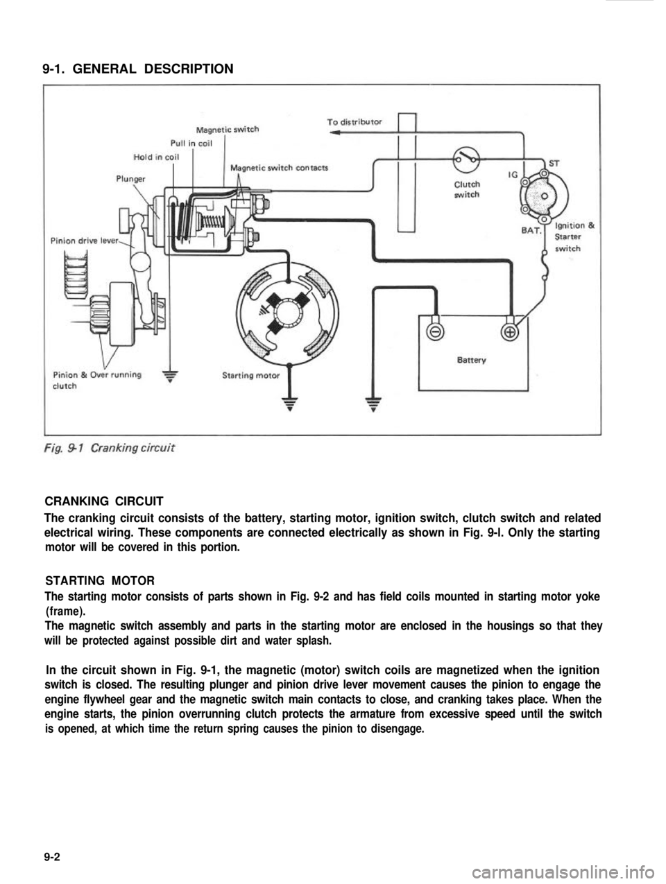
CRANKING CIRCUIT
The cranking circuit consists of the battery, starting motor, ignition switch, clutch switch and related
electrical wiring. These components are connected electrically as shown in Fig. 9-l. Only the starting
motor will be covered in this portion.
STARTING MOTOR
The starting motor consists of parts shown in Fig. 9-2 and has field coils mounted in starting motor yoke
(frame).
The magnetic switch assembly and parts in the starting motor are enclosed in the housings so that they
will be protected against possible dirt and water splash.
In the circuit shown in Fig. 9-1, the magnetic (motor) switch coils are magnetized when the ignition
switch is closed. The resulting plunger and pinion drive lever movement causes the pinion to engage the
engine flywheel gear and the magnetic switch main contacts to close, and cranking takes place. When the
engine starts, the pinion overrunning clutch protects the armature from excessive speed until the switch
is opened, at which time the return spring causes the pinion to disengage.
9-2
Page 237 of 962
A. Faulty Indicator Lamp Operation
Problem
Charge light does not light
with ignition ON and engine
off
Charge light does not go out
with engine running
(battery requires frequent
re-
charging) Possible cause
Correcti on
Fuse blown
Check fuse
Light burned outReplace light
Wiring connection loose Tighten loose connections
IC regulator faultyReplace IC regulator
Drive belt loose or worn Adjust or replace drive belt
Battery cables loose, corroded or worn Repair or replace cables
IC regulator or alternator faultyCheck charging system
Wiring faulty.Repair wiring
B. Undercharged Battery a. Voltmeter
This condition, as shown by slow cranking or indicator clear with red dot, can be caused by
one or more of the following conditions even
though the indicator lamp may be operating
normally. The following procedures also apply
to cars with a voltmeter.
1) Insure that the undercharged condition has
not been caused by accessories left on for
extended period.
2) Check drive belt for proper tension.
3) If a battery defect is suspected, refer to
latter part of this section, p. 10-l 0 - p, 1 O-
11.
4) Inspect wiring for defects. Check all connec- tions for tightness and cleanliness, including
slip connectors at alternator and bulkhead,
and battery cable connections at battery,
starter and ignition ground cable.
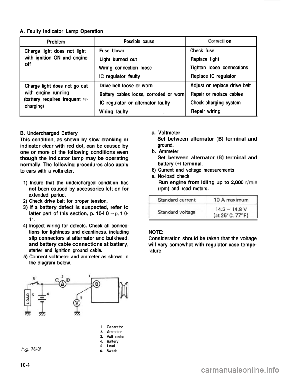
5) Connect voltmeter and ammeter as shown inthe diagram below.
Set between alternator (B) terminal and
ground.
b. Ammeter
Set between alternator (B) terminal and
battery (+) terminal.
6) Current and voltage measurements
a. No-load check
Run engine from idling up to 2,000 r/min
(rpm) and read meters.
NOTE:
Consideration should be taken that the voltage
will vary somewhat with regulator case tempe-
rature.
Fig. 10-3
10-4
1.Generator
2.Ammeter
3. Volt meter
4. Battery
6. Load
6. Switch
Page 244 of 962
![SUZUKI GRAND VITARA 1987 Service Repair Manual [Carrier and hold-down]
The battery carrier and hold-down clamp should
be clean and free from corrosion before instal-
ling the battery. The carrier should be in good
condition so that it will support SUZUKI GRAND VITARA 1987 Service Repair Manual [Carrier and hold-down]
The battery carrier and hold-down clamp should
be clean and free from corrosion before instal-
ling the battery. The carrier should be in good
condition so that it will support](/manual-img/20/57437/w960_57437-243.png)
[Carrier and hold-down]
The battery carrier and hold-down clamp should
be clean and free from corrosion before instal-
ling the battery. The carrier should be in good
condition so that it will support the battery
securely and keep it level.
Make certain there are no parts in carrier before
installing the battery.
To prevent the battery from shaking in its
carrier, the hold-down bolts should be tight but
not over tightened.
[Visual inspection]
Check for obvious damage, such as cracked or
broken case or cover, that could permit loss of
electrolyte. If obvious damage is noted, replace
the battery. Determine cause of damage and
correct as needed.
Check the battery terminal and cords for corro-
sion. If any, it should be cleaned.
[Built-in indicator]
This sealed battery has a built-in temperature
compensated indicator in the top of the battery.
This indicator is to be used with the following
diagnostic procedure. When observing the
indicator, make sure that the battery has a clean
top. A light may be needed in some poorly-lit
areas.
Under normal operation, two indications can
be seen
2
Clear
RedCHARGING
NECESSARY
Fig. lo-23
l Clear with Red Dot
This means the discharging battery. In this case,
charge the battery until the indicator will be
blue with red dot. The charging and electrical
systems should also be checked at this time. If
any defective is found, correct it. While charging
it, if the battery feels hot 52°C (125” F), or if
violent gassing or spewing of electrolyte through
the vent hole occurs, discontinue charging or
reduce charging rate.
[Jump starting in case of emergency with
auxiliary (booster) battery]
NOTE:
l Do not push or tow the vehicle to start.
Damage to the emission system and/or to
other parts of the vehicle may result.
8 Both booster and discharged battery should
be treated carefully when using jumper cables.
Follow the procedure outlined below, being
careful not to cause sparks:
CAUTION:
l Departure from these conditions or the
procedure below could result in: (1)
Serious personal injury (particularly to
eyes) or property damage from such
causes as battery explosion, battery acid,
or electrical burns; and/or (2) damage to
electronic components of either vehicle.
l Never expose battery to open flame or
electric spark-batteries generate a gas
which is flammable and explosive.
l Remove rings,watches,and other
jewelry. Wear approved eye protection.
l Do not allow battery fluid to contact
eyes, skin, fabrics, or painted surfaces -
fluid is a corrosive acid. Flush any con-
tacted area with water immediately and
thoroughly. Be careful that metal tools
or jumper cables do not contact the
positive battery terminal (or metal in
contact with it) and any other metal on
the car, because a short circuit could
occur. Batteries should always be kept
out of the reach of children.
1) Set parking brake and place transmission in
neutral. Turn off the ignition, turn off lights
and all other electrical loads.
2) Check electrolyte level. If level is below low
level line, replace battery.
NOTE:
When jump starting an engine with charging
equipment, be sure equipment used is 12volt
and negative ground. Do not use 24volt charging
equipment. Using each equipment can cause
serious damage to the electrical system or
electronic parts.
10-11
Page 375 of 962
18-7. IMPORTANT STEPS IN
REINSTALLATION
NOTE:
For installation, it is important that only the
specified screws, bolts, and nuts be used as
designated and that they are tightened to the
specified torque.
Reverse removal procedure for installation,
noting the following.
Steering Lock
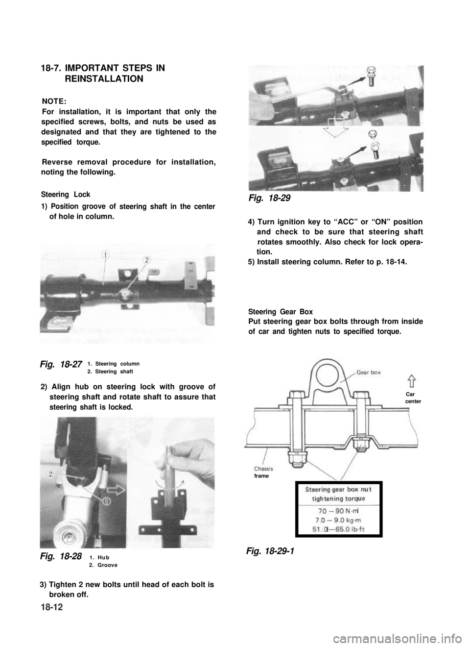
1) Position groove of
of hole in column.
steering shaft in the center
Fig. 18-271. Steering column
2. Steering shaft
2) Align hub on steering lock with groove of
steering shaft and rotate shaft to assure that
steering shaft is locked.
Fig. 18-281. Hub2. Groove
Fig. 18-29
4) Turn ignition key to “ACC” or “ON” position
and check to be sure that steering shaft
rotates smoothly. Also check for lock opera-
tion.
5) Install steering column. Refer to p. 18-14.
Steering Gear Box
Put steering gear box bolts through from inside
of car and tighten nuts to specified torque.
Carcenter
frame
Steering gear box nut
tightening torque
l-----i
-N.m
-
.O -
Fig. 18-29-1
3) Tighten 2 new bolts until head of each bolt is
broken off.
18-12
Page 456 of 962
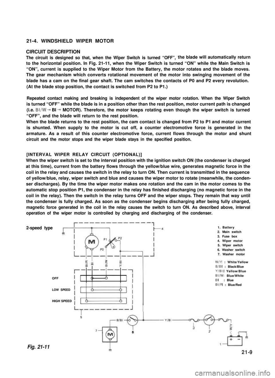
21-4. WINDSHIELD WIPER MOTOR
CIRCUIT DESCRIPTION
The circuit is designed so that, when the Wiper Switch is turned “OFF”,the blade will automatically return
to the horizontal position. In Fig. 21-11, when the Wiper Switch is turned “ON” while the Main Switch is
“ON”, current is supplied to the Wiper Motor from the Battery, the motor rotates and the blade moves.
The gear mechanism which converts rotational movement of the motor into swinging movement of the
blade has a cam on the final gear shaft. The cam switches the contacts of P0 and P2 every revolution.
(At the blade stop position, the contact is switched from P2 to P1.)
Repeated contact making and breaking is independent of the wiper motor rotation. When the Wiper Switch
is turned “OFF” while the blade is in a position other than the rest position, motor current path is changed
(i.e. BI/W + BI + MOTOR). Therefore, the motor keeps rotating even though the wiper switch is turned
“OFF”, and the blade will return to the rest position.
When the blade returns to the rest position, the cam contact is changed from P2 to P1 and motor current
is shunted. When supply to the motor is cut off, a counter electromotive force is generated in the
armature. As a result of this counter electromotive force, current flows through the motor and shunt
circuit and the motor stops and the wiper blade stays in the specified position.
[INTERVAL WIPER RELAY CIRCUIT (OPTIONAL)]
When the wiper switch is set to the interval position with the ignition switch ON (the condenser is charged
at this time), current from the battery flows through the yellow/blue wire, generates magnetic force in the
coil in the relay and causes the switch in the relay to turn ON. Then current is transmitted in the sequence
of yellow/blue, relay, wiper switch and blue and causes the wiper motor to rotate (meanwhile, the conden-
ser discharges). By the time the wiper motor makes one rotation and the cam in the motor comes to the
automatic stop position P1, the condenser in the relay has finished discharging (no magnetic force in the
coil in the relay). Then the switch in the relay turns OFF and the wiper stops. They remain that way until
the condenser is fully charged. As soon as the condenser begins discharging after being fully charged,
magnetic force generated in the coil in the relay causes the switch to turn ON. As described above, interval
operation of the wiper motor is controlled by charging and discharging of the condenser.
2-speed type
OFF
1. Battery2. Main switch
3. Fuse box4. Wiper motor5. Wiper switch
6. Washer switch7. Washer motor
W/Y : White/Yellow
B/BI : Black/Blue
Y/El: Yellow/Blue
BI/W: Blue/WhiteBI: Blue
LOW SPEED
BIIR : Blue/Red
HIGH SPEED
Fig. 21-11
6
21-9
Page 459 of 962
![SUZUKI GRAND VITARA 1987 Service Repair Manual [Gauge unit] 21-6. FUEL LEVEL METER AND GAUGE
Warm up gauge unit. Thus make sure its resis-
tance is decreased with increase of temperature.
Temperature and resistance relationship can be
plotted in a SUZUKI GRAND VITARA 1987 Service Repair Manual [Gauge unit] 21-6. FUEL LEVEL METER AND GAUGE
Warm up gauge unit. Thus make sure its resis-
tance is decreased with increase of temperature.
Temperature and resistance relationship can be
plotted in a](/manual-img/20/57437/w960_57437-458.png)
[Gauge unit] 21-6. FUEL LEVEL METER AND GAUGE
Warm up gauge unit. Thus make sure its resis-
tance is decreased with increase of temperature.
Temperature and resistance relationship can be
plotted in a graph as shown below.
The fuel level meter circuit consists of the fuel
level meter installed inside the combination
meter and the fuel level gauge installed to the
fuel tank.
Fig. 21-17
wTemp.
Fig. 21-18 Resistance- Temp. Relationship
Temperature
50°C (122°F)
80°C (176°F)
100°C (212°F)
Resistance
133.9 -178.9 f-i
47.5-56.8 !a
26.2 -29.3 52
Current flowing through the meter coil is
changed to control the meter pointer. That is,
when fuel is full, the fuel level gauge unit
resistance is decreased with more current flowing
into the meter coil, causing the meter pointer
to point at the “F” position.
INSPECTION
[Fuel level meter]
1. Disconnect Y/R (Yellow/Red) lead wire
going to gauge unit.
2. Use a bulb (12V 3.4W) in position to ground
above lead wire as illustrated.
3. Turn ignition switch ON.
Make sure the bulb is lighted and meter
pointer fluctuates several seconds thereafter.
If meter is faulty, replace it.
Fig. 21-191. Battery2. Fuel level meter
3. Test lamp (12V. 3.4%‘)YR : Yellow/Red
NOTE:
Wind sealing tape on screw threads of gauge
before installing gauge to intake manifold.
21-12