1987 SUZUKI GRAND VITARA ignition
[x] Cancel search: ignitionPage 141 of 962
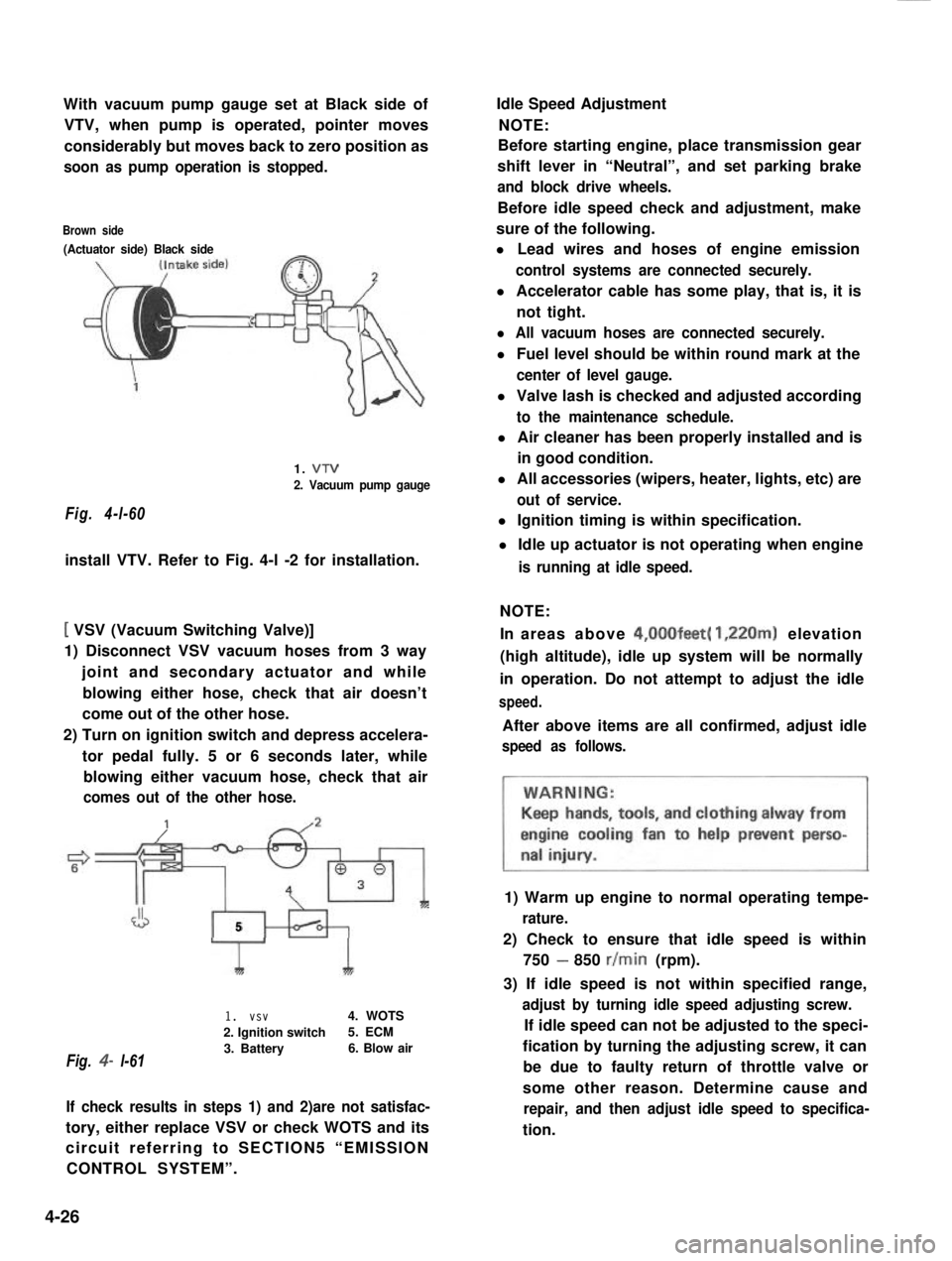
With vacuum pump gauge set at Black side of
VTV, when pump is operated, pointer moves
considerably but moves back to zero position as
soon as pump operation is stopped.
Brown side
(Actuator side) Black side
Fig. 4-l-60
1. VTV
2. Vacuum pump gauge
install VTV. Refer to Fig. 4-l -2 for installation.
[ VSV (Vacuum Switching Valve)]
1) Disconnect VSV vacuum hoses from 3 way
joint and secondary actuator and while
blowing either hose, check that air doesn’t
come out of the other hose.
2) Turn on ignition switch and depress accelera-
tor pedal fully. 5 or 6 seconds later, while
blowing either vacuum hose, check that air
comes out of the other hose.
J5
Fig. 4- l-61
1I
1. vsv4. WOTS
2. Ignition switch5. ECM
3. Battery6. Blow air
If check results in steps 1) and 2)are not satisfac-
tory, either replace VSV or check WOTS and its
circuit referring to SECTION5 “EMISSION
CONTROL SYSTEM”.
Idle Speed Adjustment
NOTE:
Before starting engine, place transmission gear
shift lever in “Neutral”, and set parking brake
and block drive wheels.
Before idle speed check and adjustment, make
sure of the following.
l Lead wires and hoses of engine emission
control systems are connected securely.
l Accelerator cable has some play, that is, it is
not tight.
l All vacuum hoses are connected securely.
l Fuel level should be within round mark at the
center of level gauge.
l Valve lash is checked and adjusted according
to the maintenance schedule.
l Air cleaner has been properly installed and is
in good condition.
l All accessories (wipers, heater, lights, etc) are
out of service.
l Ignition timing is within specification.
l Idle up actuator is not operating when engine
is running at idle speed.
NOTE:
In areas above 4,00Ofeet( 1,220m) elevation
(high altitude), idle up system will be normally
in operation. Do not attempt to adjust the idle
speed.
After above items are all confirmed, adjust idle
speed as follows.
1) Warm up engine to normal operating tempe-
rature.
2) Check to ensure that idle speed is within
750 - 850 r/min (rpm).
3) If idle speed is not within specified range,
adjust by turning idle speed adjusting screw.
If idle speed can not be adjusted to the speci-
fication by turning the adjusting screw, it can
be due to faulty return of throttle valve or
some other reason. Determine cause and
repair, and then adjust idle speed to specifica-
tion.
4-26
Page 143 of 962

3) Reinstall carburetor following normal service
procedures.
Connect emission control system hoses and
lead wires. Make specified play on accelerator
cable and refill cooling system.
4) Place transaxle gear shift lever in “Neutral”,
set parking brake and block drive wheels.
5) Start engine, and warm it up to normal
operating temperature, stop engine.
6) Be sure to check the following before idle
mixture adjustment.
l Fuel level is within round mark at the
center of level gauge.
l Valve lash is checked and adjusted accord-
ing to the maintenance schedule.
l Air cleaner has been properly installed
and is in good condition.
l All accessories (wipers, heater, lights etc)
are out of service.
l Ignition timing is within specification.
l Choke valve opens fully.
l Idle-up actuator does not operate.
7) Check and adjust idle speed to specification
if necessary.
8) Remove seal rubber of duty check coupler
and connect positive terminal of duty
meter to“Blue/Red” wire and negative
terminal to “Black/Green” wire.
9) Run engine at 1,500 - 2,000 r/min for 30
seconds and bring it to idle speed.
10) With engine running at idle speed, adjust idle
mixture adjusting screw slowly in small incre-
ment allowing time for duty to stabilize after
turning screw to obtain duty of 10 - 50.
If duty is too low, back screw out; if too
high, screw it in. After obtaining duty of
10 - 50, recheck idle speed, and adjust if
necessary.
NOTE:
If adjustment can’t be made because duty meter
indicator does not deflect, check feed back
system according to the checking procedure of
system described in section of Emission Control
System.
11) After adjustment, install seal rubber to duty
check coupler and drive in idle mixture
adjusting screw pin.
4-28
Page 158 of 962
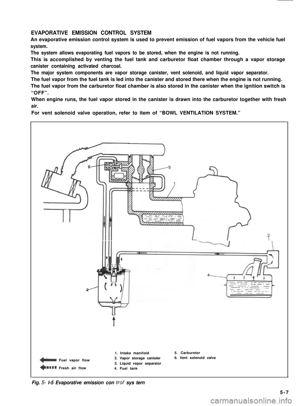
EVAPORATIVE EMISSION CONTROL SYSTEM
An evaporative emission control system is used to prevent emission of fuel vapors from the vehicle fuel
system.
The system allows evaporating fuel vapors to be stored, when the engine is not running.
This is accomplished by venting the fuel tank and carburetor float chamber through a vapor storage
canister containing activated charcoal.
The major system components are vapor storage canister, vent solenoid, and liquid vapor separator.
The fuel vapor from the fuel tank is led into the canister and stored there when the engine is not running.
The fuel vapor from the carburetor float chamber is also stored in the canister when the ignition switch is
“OFF”.
When engine runs, the fuel vapor stored in the canister is drawn into the carburetor together with fresh
air.
For vent solenoid valve operation, refer to item of “BOWL VENTILATION SYSTEM.”
2
1 Fuel vapor flow
+llal Fresh air flow
1. Intake manifold2. Vapor storage canister
3. Liquid vapor separator4. Fuel tank
5. Carburetor6. Vent solenoid valve
Fig. 5- l-5 Evaporative emission con trot sys tern
5-7
Page 162 of 962
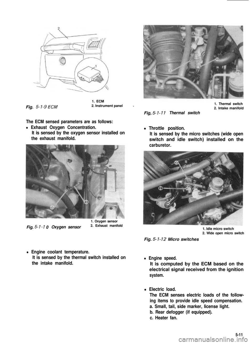
Fig. 5- l-9 ECM
1. ECM
2. Instrument panel.
The ECM sensed parameters are as follows:
l Exhaust Oxygen Concentration.
It is sensed by the oxygen sensor installed on
the exhaust manifold.
1. Oxygen sensor
Fig. 5- I - 7 0Oxygen sensor2. Exhaust manifold
l Engine coolant temperature.
It is sensed by the thermal switch installed on
the intake manifold.
1. Thermal switch
2. Intake manifold
Fig, 5- I- 17Thermal switch
l Throttle position.
It is sensed by the micro switches (wide open
switch and idle switch) installed on the
carburetor.
1. Idle micro switch
2. Wide open micro switch
Fig. 5- 1-12 Micro switches
l Engine speed.
It is computed by the ECM based on the
electrical signal received from the ignition
system.
l Electric load.
The ECM senses electric loads of the follow-
ing items to provide idle speed compensation.
a. Small, tail, side marker, license light.
b. Rear defogger (if equipped).
c. Heater fan.
5-11
Page 163 of 962
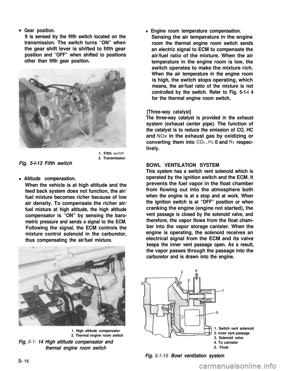
Gear position.
It is sensed by the fifth switch located on the
transmission. The switch turns “ON” when
the gear shift lever is shifted to fifth gear
position and “OFF” when shifted to positions
other than fifth gear position.
1. Fifth swirch
2. Transmission
Fig. 5-l-13 Fifth switch
l Altitude compensation.
When the vehicle is at high altitude and the
feed back system does not function, the air/
fuel mixture becomes richer because of low
air density. To compensate the richer air/
fuel mixture at high altitude, the high altitude
compensator is “ON” by sensing the baro-
metric pressure and sends a signal to the ECM.
Following the signal, the ECM controls the
mixture control solenoid in the carburetor,
thus compensating the air/fuel mixture.
1. High altitude compensator2. Thermal engine room switch
Fig. 5- I- 14 High altitude compensator and
thermal engine room switch
l Engine room temperature compensation.
Sensing the air temperature in the engine
room the thermal engine room switch sends
an electric signal to ECM to compensate the
air/fuel ratio of the mixture. When the air
temperature in the engine room is low, the
switch operates to make the mixture rich.
When the air temperature in the engine room
is high, the switch stops operating, which
means, the air/fuel ratio of the mixture is not
controlled by the switch. Refer to Fig. 5-1-l 4
for the thermal engine room switch.
[Three-way catalyst]
The three-way catalyst is provided in the exhaust
system (exhaust center pipe). The function of
the catalyst is to reduce the emission of CO, HC
and NOx in the exhaust gas by oxidizing or
converting them into CO2, Hz 0 and Nz respec-
tively.
BOWL VENTILATION SYSTEM
This system has a switch vent solenoid which is
operated by the ignition switch and the ECM. It
prevents the fuel vapor in the float chamber
from flowing out into the atmosphere both
when the engine is at a stop and at work. When
the ignition switch is at “OFF” position or when
cranking the engine (engine not started), the
vent passage is closed by the solenoid valve, and
therefore, the vapor flows from the float cham-
ber into the vapor storage canister. When the
engine is operating, the solenoid receives an
electrical signal from the ECM and its valve
keeps the inner vent passage open. As a result,
the vapor passes through the passage into the
carburetor and is drawn into the engine.
1. Switch vent solenoid
2. inner vent passage3. Solenoid valve
4. To canister
5. Float
Fig. 5-l-15 Bowl ventilation system
5-12
Page 164 of 962
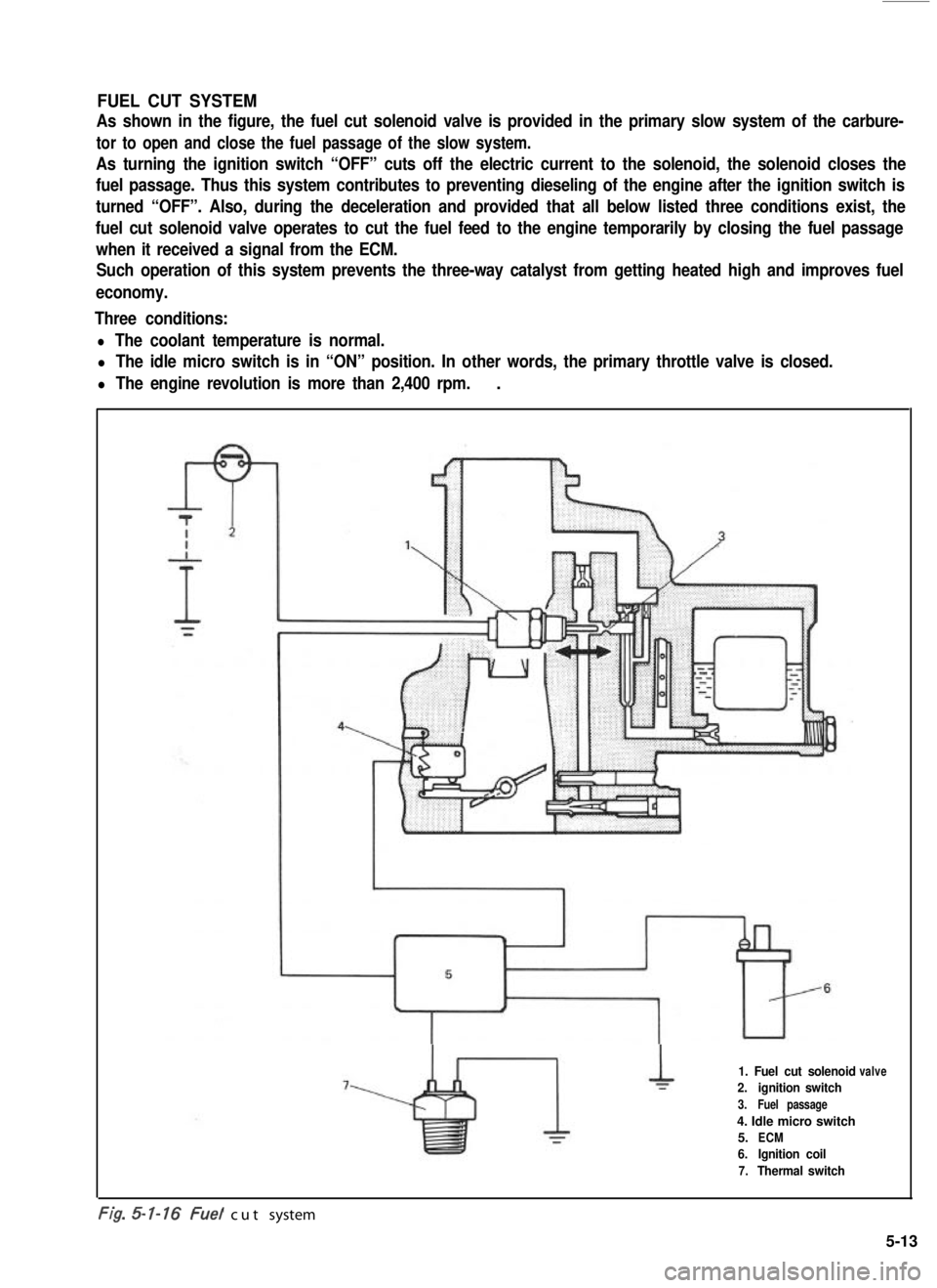
FUEL CUT SYSTEM
As shown in the figure, the fuel cut solenoid valve is provided in the primary slow system of the carbure-
tor to open and close the fuel passage of the slow system.
As turning the ignition switch “OFF” cuts off the electric current to the solenoid, the solenoid closes the
fuel passage. Thus this system contributes to preventing dieseling of the engine after the ignition switch is
turned “OFF”. Also, during the deceleration and provided that all below listed three conditions exist, the
fuel cut solenoid valve operates to cut the fuel feed to the engine temporarily by closing the fuel passage
when it received a signal from the ECM.
Such operation of this system prevents the three-way catalyst from getting heated high and improves fuel
economy.
Three conditions:
l The coolant temperature is normal.
l The idle micro switch is in “ON” position. In other words, the primary throttle valve is closed.
l The engine revolution is more than 2,400 rpm..
1. Fuel cut solenoid
2.ignition switch
3.Fuel passage
4. Idle micro switch
5.ECM
6.Ignition coil
7.Thermal switch
valve
-. .t/g. cut system
5-13
Page 171 of 962
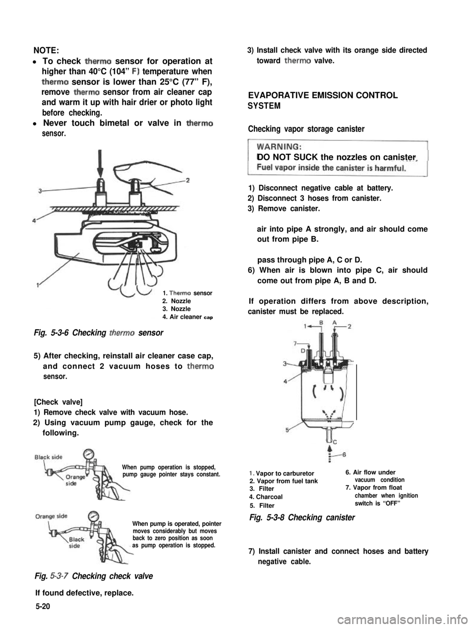
NOTE:
l To check therm0 sensor for operation at
higher than 40°C (104” F) temperature when
therm0 sensor is lower than 25°C (77” F),
remove therm0 sensor from air cleaner cap
and warm it up with hair drier or photo light
before checking.
l Never touch bimetal or valve in therm0
sensor.
1. Therm0 sensor
2. Nozzle3. Nozzle
4. Air cleaner cap
Fig. 5-3-6 Checking therm0 sensor
5) After checking, reinstall air cleaner case cap,
and connect 2 vacuum hoses to therm0
sensor.
[Check valve]
1) Remove check valve with vacuum hose.
2) Using vacuum pump gauge, check for the
following.
When pump operation is stopped,pump gauge pointer stays constant.
When pump is operated, pointermoves considerably but movesback to zero position as soonas pump operation is stopped.
Fig. 5-3-7 Checking check valve
If found defective, replace.
3) Install check valve with its orange side directed
toward therm0 valve.
EVAPORATIVE EMISSION CONTROL
SYSTEM
Checking vapor storage canister
DO NOT SUCK the nozzles on canister
1) Disconnect negative cable at battery.
2) Disconnect 3 hoses from canister.
3) Remove canister.
air into pipe A strongly, and air should come
out from pipe B.
pass through pipe A, C or D.
6) When air is blown into pipe C, air should
come out from pipe A, B and D.
If operation differs from above description,
canister must be replaced.
1. Vapor to carburetor6. Air flow under
2. Vapor from fuel tankvacuum condition
3. Filter7. Vapor from float
4. Charcoalchamber when ignition
5. Filterswitch is “OFF”
Fig. 5-3-8 Checking canister
7) Install canister and connect hoses and battery
negative cable.
5-20
Page 174 of 962
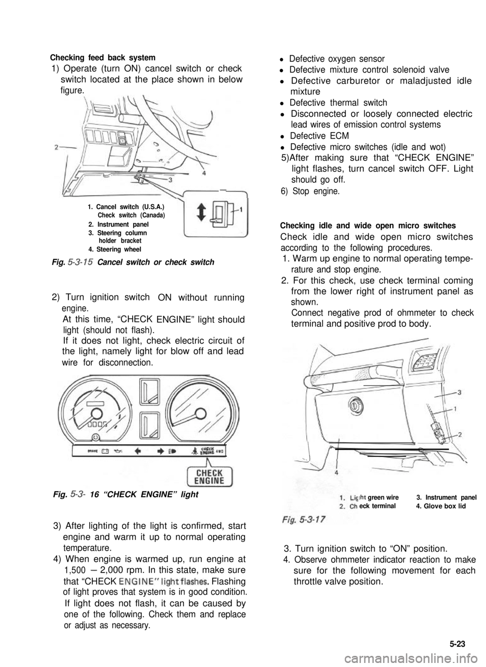
Checking feed back system
1) Operate (turn ON) cancel switch or check
l Defective oxygen sensor
l Defective mixture control solenoid valve
switch located at the place shown in belowl Defective carburetor or maladjusted idle
figure.mixture
-
1. Cancel switch (U.S.A.)Check switch (Canada)
2. Instrument panel
w
$
1
3. Steering columnholder bracket
4. Steering wheel
Fig. 5-3- 15 Cancel switch or check switch
2) Turn ignition switch
engine.
At this time, “CHECK
ON without running
ENGINE” light should
light (should not flash).
If it does not light, check electric circuit of
the light, namely light for blow off and lead
wire for disconnection.
Fig. 5-3- 16 “CHECK ENGINE” light
3) After lighting of the light is confirmed, start
engine and warm it up to normal operating
temperature.
4) When engine is warmed up, run engine at
1,500- 2,000 rpm. In this state, make sure
that “CHECK ENGINE”lightflashes. Flashing
of light proves that system is in good condition.
If light does not flash, it can be caused by
one of the following. Check them and replace
or adjust as necessary.
l Defective thermal switch
l Disconnected or loosely connected electric
lead wires of emission control systems
l Defective ECM
l Defective micro switches (idle and wot)
5)After making sure that “CHECK ENGINE”
light flashes, turn cancel switch OFF. Light
should go off.
6) Stop engine.
Checking idle and wide open micro switches
Check idle and wide open micro switches
according to the following procedures.
1. Warm up engine to normal operating tempe-
rature and stop engine.
2. For this check, use check terminal coming
from the lower right of instrument panel as
shown.
Connect negative prod of ohmmeter to check
terminal and positive prod to body.
Iht green wire
eck terminal
3. Instrument panel
4. Glove box lid
3. Turn ignition switch to “ON” position.
4. Observe ohmmeter indicator reaction to make
sure for the following movement for each
throttle valve position.
5-23