Page 195 of 962
6-2. .REMOVAL
WARNING:
l Check to make sure that cooling water
temperature is cold before removing any
part of cooling system components.
l Also be sure to disconnect 0 cord from
battery 0 terminal before removing any
part.
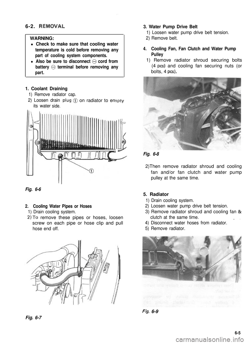
1. Coolant Draining
1) Remove radiator cap.
2) Loosen drain
its waterside.
-on radiator to enPtY
-
Illi
Fig. 6-6
2.Cooling Water Pipes or Hoses
1) Drain cooling system.
2)To remove these pipes or hoses, loosen
screw on each pipe or hose clip and pull
hose end off.
3. Water Pump Drive Belt
1) Loosen water pump drive belt tension.
2) Remove belt.
4.Cooling Fan, Fan Clutch and Water Pump
Pulley
1) Remove radiator shroud securing bolts
(4 PCS) and cooling fan securing nuts (or
bolts, 4 pcs).
Fig. 6-8
2)Then remove radiator shroud and cooling
fan and/or fan clutch and water pump
pulley at the same time.
5. Radiator
1) Drain cooling system.
2) Loosen water pump drive belt tension.
3) Remove radiator shroud and cooling fan &
clutch at the same time.. ”
4) Disconnect water hoses from radiator.
5) Remove radiator.
FI& 6-9
Fig. 6-7
6-5
Page 196 of 962
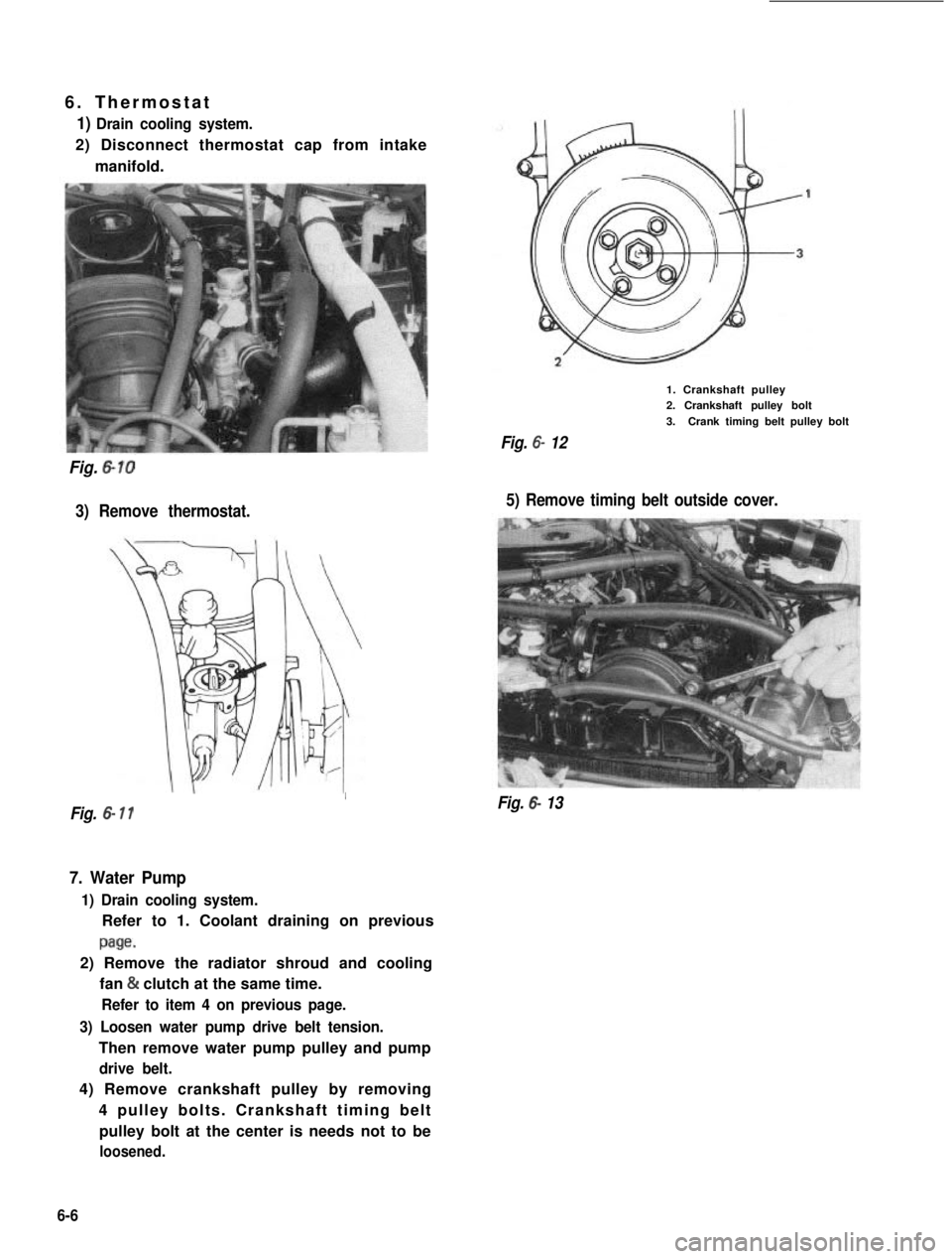
6. Thermostat
1) Drain cooling system.
2) Disconnect thermostat cap from intake
manifold.
Fig. 6-10
3) Remove thermostat.
1. Crankshaft pulley2. Crankshaft pulley bolt
3.Crank timing belt pulley bolt
Fig. 6- 12
5) Remove timing belt outside cover.
I
Fig. 6- 11Fig. 6- 13
7. Water Pump
1) Drain cooling system.
Refer to 1. Coolant draining on previous
page.
2) Remove the radiator shroud and cooling
fan & clutch at the same time.
Refer to item 4 on previous page.
3) Loosen water pump drive belt tension.
Then remove water pump pulley and pump
drive belt.
4) Remove crankshaft pulley by removing
4 pulley bolts. Crankshaft timing belt
pulley bolt at the center is needs not to be
loosened.
6-6
Page 197 of 962
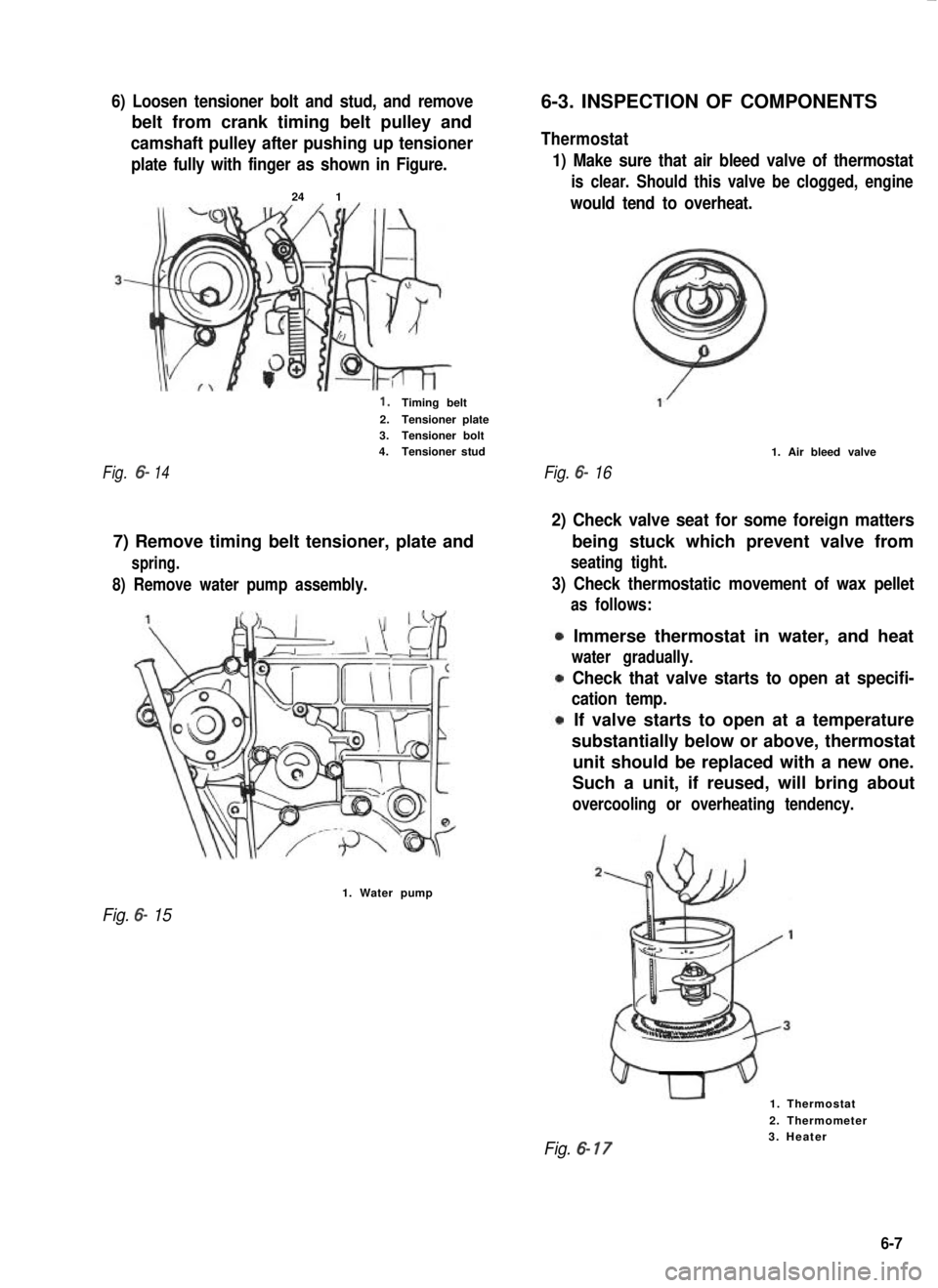
6) Loosen tensioner bolt and stud, and remove
belt from crank timing belt pulley and
camshaft pulley after pushing up tensioner
plate fully with finger as shown in Figure.
24 1
1.Timing belt
2.Tensioner plate3.Tensioner bolt4.Tensioner stud
Fig.6-14
8) Remove water pump assembly.
7) Remove timing belt tensioner, plate and
spring.
1. Water pump
Fig. 6- 15
6-3. INSPECTION OF COMPONENTS
Thermostat
1) Make sure that air bleed valve of thermostat
is clear. Should this valve be clogged, engine
would tend to overheat.
Fig. 6- 16
1. Air bleed valve
2) Check valve seat for some foreign matters
3) Check thermostatic movement of wax pellet
being stuck which prevent valve from
seating tight.
as follows:
Immerse thermostat in water, and heat
water gradually.
Check that valve starts to open at specifi-
cation temp.
If valve starts to open at a temperature
substantially below or above, thermostat
unit should be replaced with a new one.
Such a unit, if reused, will bring about
overcooling or overheating tendency.
1. Thermostat
2. Thermometer
Fig. 6- 173. Heater
6-7
Page 198 of 962
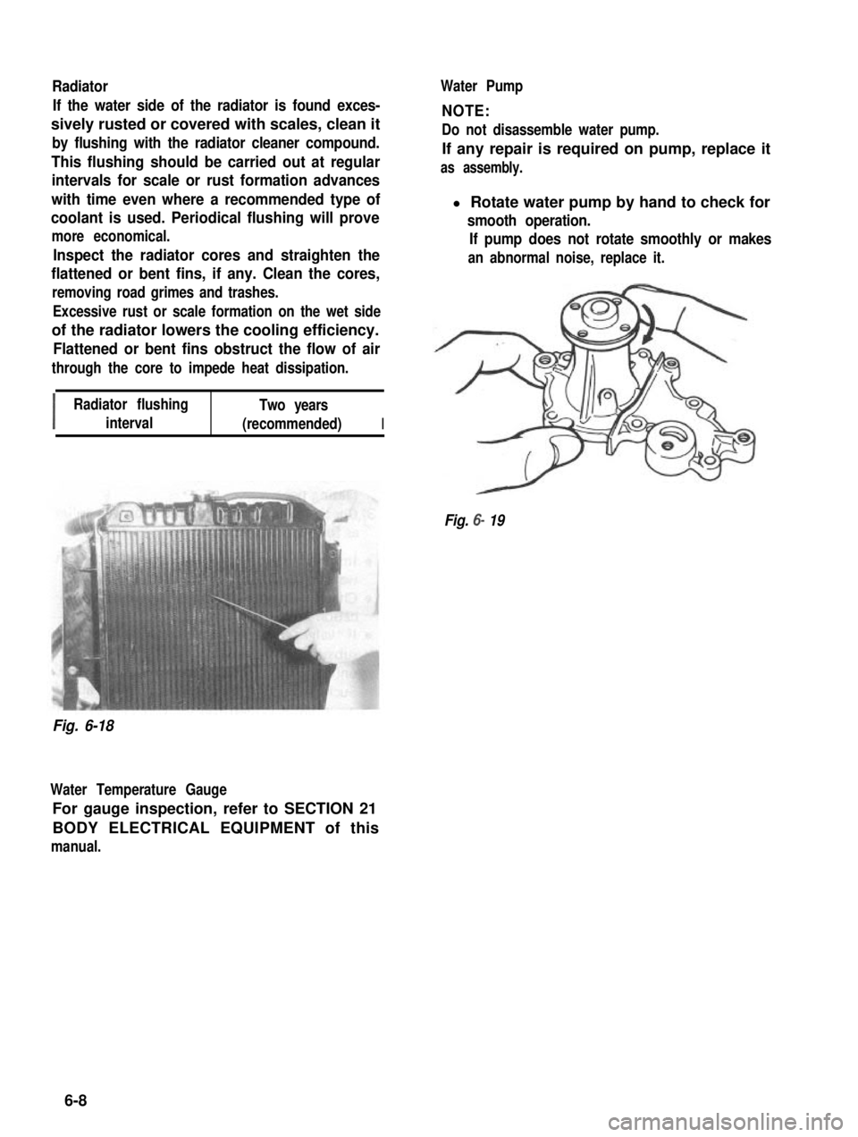
Radiator
If the water side of the radiator is found exces-
sively rusted or covered with scales, clean it
by flushing with the radiator cleaner compound.
This flushing should be carried out at regular
intervals for scale or rust formation advances
with time even where a recommended type of
coolant is used. Periodical flushing will prove
more economical.
Inspect the radiator cores and straighten the
flattened or bent fins, if any. Clean the cores,
removing road grimes and trashes.
Excessive rust or scale formation on the wet side
of the radiator lowers the cooling efficiency.
Flattened or bent fins obstruct the flow of air
through the core to impede heat dissipation.
I
Radiator flushingTwo years
interval(recommended)I
Water Pump
NOTE:
Do not disassemble water pump.
If any repair is required on pump, replace it
as assembly.
l Rotate water pump by hand to check for
smooth operation.
If pump does not rotate smoothly or makes
an abnormal noise, replace it.
Fig. 6- 19
Fig. 6-18
Water Temperature Gauge
For gauge inspection, refer to SECTION 21
BODY ELECTRICAL EQUIPMENT of this
manual.
6-8
Page 199 of 962
6-4. IMPORTANT STEPS FOR
REINSTALLATION
Water Pump
1) Install new pump gasket to cylinder block.
2) Install water pump to cylinder block.
Tightening torque
for bolts & nuts
lo- 13 N-m
1 .O - 1.3 kg-m
7.5 - 9.0 lb-ft
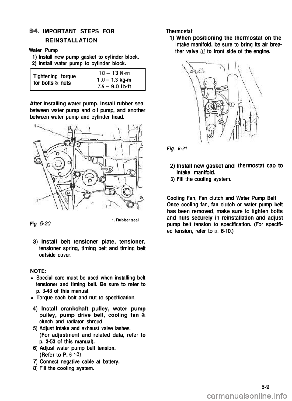
After installing water pump, install rubber seal
between water pump and oil pump, and another
between water pump and cylinder head.
Fig, 6-201. Rubber seal
3) Install belt tensioner plate, tensioner,
tensioner spring, timing belt and timing belt
outside cover.
NOTE:
l Special care must be used when installing belt
tensioner and timing belt. Be sure to refer to
p. 3-48 of this manual.
l Torque each bolt and nut to specification.
4) Install crankshaft pulley, water pump
pulley, pump drive belt, cooling fan &
clutch and radiator shroud.
5) Adjust intake and exhaust valve lashes.
(For adjustment and related data, refer to
p. 3-53 of this manual).
6) Adjust water pump belt tension.
(Refer to P. 6-10).
7) Connect negative cable at battery.
8) Fill the cooling system.
Thermostat
1) When positioning the thermostat on the
intake manifold, be sure to bring its air brea-
ther valve (iJ to front side of the engine.
Fig. 6-21
2) Install new gasket and
intake manifold.
3) Fill the cooling system.
thermostat cap to
Cooling Fan, Fan clutch and Water Pump Belt
Once cooling fan, fan clutch or water pump belt
has been removed, make sure to tighten bolts
and nuts securely in reinstallation and adjust
pump belt tension to specification. (For specifi-
ed tension, refer to p. 6-10.)
6-9
Page 200 of 962
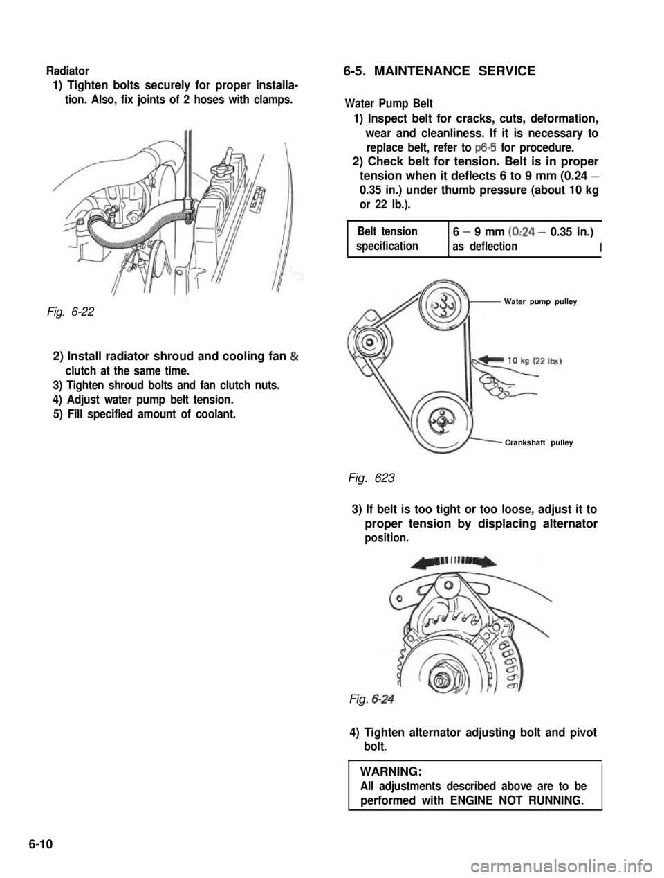
Radiator6-5. MAINTENANCE SERVICE
1) Tighten bolts securely for proper installa-
tion. Also, fix joints of 2 hoses with clamps.
Fig. 6-22
2) Install radiator shroud and cooling fan &
clutch at the same time.
3) Tighten shroud bolts and fan clutch nuts.
4) Adjust water pump belt tension.
5) Fill specified amount of coolant.
Water Pump Belt
1) Inspect belt for cracks, cuts, deformation,
wear and cleanliness. If it is necessary to
replace belt, refer to ~6-5 for procedure.
2) Check belt for tension. Belt is in proper
tension when it deflects 6 to 9 mm (0.24 -
0.35 in.) under thumb pressure (about 10 kg
or 22 lb.).
Belt tension
specification
6 - 9 mm (0:24 - 0.35 in.)
as deflectionI
Water pump pulley
Crankshaft pulley
Fig. 623
3) If belt is too tight or too loose, adjust it to
proper tension by displacing alternator
position.
Fig. 6-
4) Tighten alternator adjusting bolt and pivot
bolt.
WARNING:
All adjustments described above are to be
performed with ENGINE NOT RUNNING.
6-10
Page 243 of 962
3) Make sure to assemble stator terminal
insulator properly.
10-2. BATTERY
1. Stator terminal insulator
Fig. lo-20
4) Alternator V belt tension.
1. Crankshaft pulley
2. Water pump pulley
3. Alternator pulley
A :Belt deflection
Fig. 1021
Drive belt deflection
(Under 10 kg thumb
pressure)
6-9mm
(0.24 - 0.35 in)
NOTE:
Clamp brake pipe with pipe clamp on radiator
under cover after installing radiator under cover.
GENERAL DESCRIPTION
The battery has three major functions in the
electrical system. First, it is a source of electrical
energy for cranking the engine. Second it acts as
a voltage stabilizer for the electrical system. And
third, it can, for a limited time, provide energy
when the electrical load exceeds the output of
the generator.
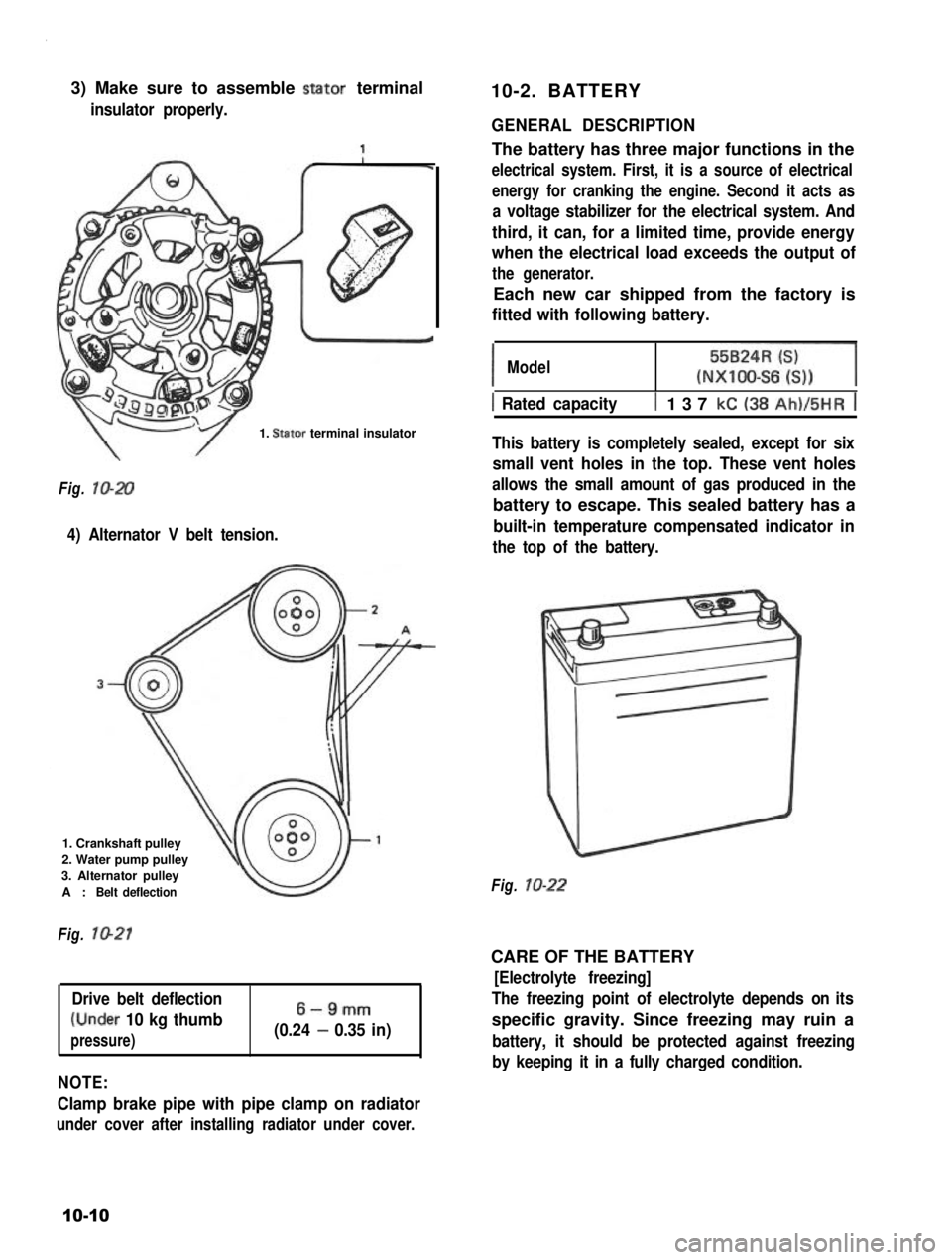
Each new car shipped from the factory is
fitted with following battery.
IModel55BzR=l(NXIOO-S6 6))
1 Rated capacityt 137 kC (38 Ah)/5HR j
This battery is completely sealed, except for six
small vent holes in the top. These vent holes
allows the small amount of gas produced in the
battery to escape. This sealed battery has a
built-in temperature compensated indicator in
the top of the battery.
Fig. lo-22
CARE OF THE BATTERY
[Electrolyte freezing]
The freezing point of electrolyte depends on its
specific gravity. Since freezing may ruin a
battery, it should be protected against freezing
by keeping it in a fully charged condition.
10-10
Page:
< prev 1-8 9-16 17-24