1987 SUZUKI GRAND VITARA steering
[x] Cancel search: steeringPage 52 of 962

2-9. SUSPENSION, STEERING SYSTEM AND TIRES
Condition
Hard steering
Possible causeCorrection
1. Wheel tires not adequately inflatedAdjust the pressure
2. Bind in tie rod end ball studReplace
3. Linkage connections tending to seizeRepair or replace
4. Steering gearbox out of adjustmentAdjust as prescribed
5. Unevenly worn steering shaft bushReplace
6. Disturbed front wheel alignmentAdjust as prescribed
Wobbly steering wheel1. Wheel tires inflated unequallyAdjust tire pressure
(Shimmy, shake or2. Wobbly wheelsRepair or replace
vibration)3. Large difference in tire diameter betweenReplace._
right and left wheels
4. Loose hub nutsRetighten
5. Damaged or worn wheel bearingsReplace
6. Worn or loose tie rod endsReplace or retighten
7. Steering gearbox out of adjustmentAdjust as prescribed
8. Steering gearbox mounted looseRetighten
9. Worn steering knuckle oil sealReplace
10. Tire or wheel out of balanceBalance wheel or replace tire
and/or wheel
11. Blister or bump on tireReplace tire
12. Disturbed front wheel alignmentCheck front wheel alignment
Steering wheel
pulling to one
side (car pulls)
1. Unevenly worn wheel tires
2. Brake dragging in one road wheel
3. Wheel tires unequally inflated
4. Worn or distorted link rods
5. Disturbed front wheel alignment
6. Loose, bent or broken front or rear
suspension parts
Replace
Repair
Adjust tire pressure
Replace
Adjust as prescribed
Tighten or replace suspension
parts
Shocks coming to1. Tire inflating pressure too highReduce to the specification
steering wheel2. Poor shock absorber performanceReplace
(or wheel tramp)3. Differences in tire diameter among fourAdjust
road wheels
4. Worn steering linkage connectionsReplace
5. Worn or broken front wheel bearingsReplace
6. Loose front wheelRetighten
7. Steering wheel loose in placeRetighten the nut
8. Blister or bump on tireReplace tire
Rapid wear or uneven1. Wheel tires imporperly inflatedAdjust tire pressure
wear of wheel tires2. Differences in diameter among four tiresAdjust or replace
(Abnormal or excessive3. Worn or loose road wheel bearingsReplace
tire wear)4. Wobbly wheel tiresRepair or replace
2-14
Page 53 of 962
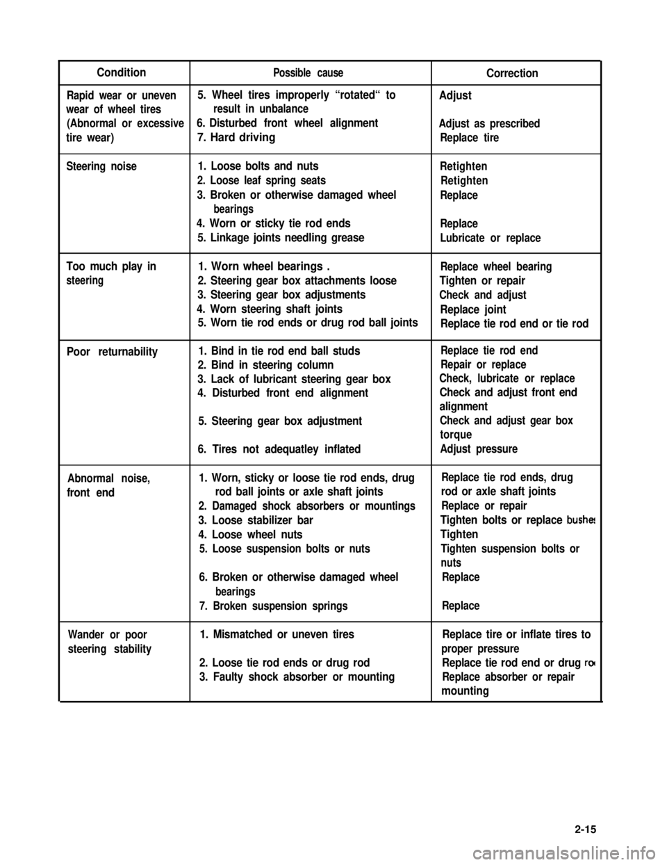
ConditionPossible causeCorrection
Rapid wear or uneven5. Wheel tires improperly “rotated“ toAdjust
wear of wheel tiresresult in unbalance
(Abnormal or excessive6. Disturbed front wheel alignmentAdjust as prescribed
tire wear)7. Hard drivingReplace tire
Steering noise1. Loose bolts and nuts
2. Loose leaf spring seats
3. Broken or otherwise damaged wheel
bearings
4. Worn or sticky tie rod ends
5. Linkage joints needling grease
Retighten
Retighten
Replace
Replace
Lubricate or replace
Too much play in
steering
1. Worn wheel bearings .Replace wheel bearing
2. Steering gear box attachments looseTighten or repair
3. Steering gear box adjustmentsCheck and adjust
4. Worn steering shaft jointsReplace joint
5. Worn tie rod ends or drug rod ball jointsReplace tie rod end or tie rod
Poor returnability1. Bind in tie rod end ball studs
2. Bind in steering column
3. Lack of lubricant steering gear box
4. Disturbed front end alignment
5. Steering gear box adjustment
6. Tires not adequatley inflated
Replace tie rod end
Repair or replace
Check, lubricate or replace
Check and adjust front end
alignment
Check and adjust gear box
torque
Adjust pressure
Abnormal noise,
front end
1. Worn, sticky or loose tie rod ends, drug
rod ball joints or axle shaft joints
2. Damaged shock absorbers or mountings
3. Loose stabilizer bar
4. Loose wheel nuts
5. Loose suspension bolts or nuts
6. Broken or otherwise damaged wheel
bearings
7. Broken suspension springs
Replace tie rod ends, drug
rod or axle shaft joints
Replace or repair
Tighten bolts or replace bushe!
Tighten
Tighten suspension bolts or
nuts
Replace
Replace
Wander or poor
steering stability
1. Mismatched or uneven tires
2. Loose tie rod ends or drug rod
3. Faulty shock absorber or mounting
Replace tire or inflate tires to
proper pressure
Replace tie rod end or drug ro(
Replace absorber or repair
mounting
2-15
Page 54 of 962
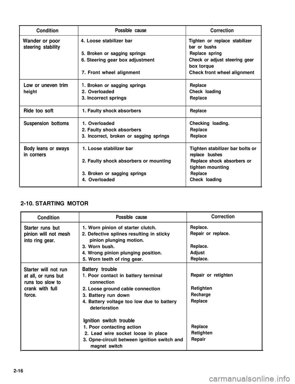
Condition
Wander or poor
steering stability
Low or uneven trim
height
Ride too soft
Suspension bottoms
Body leans or sways
in corners
Possible cause
4. Loose stabilizer bar
5. Broken or sagging springs
6. Steering gear box adjustment
7. Front wheel alignment
1. Broken or sagging springs
2. Overloaded
3. Incorrect springs
1. Faulty shock absorbers
1. Overloaded
2. Faulty shock absorbers
3. Incorrect, broken or sagging springs
1. Loose stabilizer bar
2. Faulty shock absorbers or mounting
3. Broken or sagging springs
4. Overloaded
Correction
Tighten or replace stabilizer
bar or bushs
Replace spring
Check or adjust steering gear
box torque
Check front wheel alignment
Replace
Check loading
Replace
Replace
Checking loading.
Replace
Replace
Tighten stabilizer bar bolts or
replace bushes
Replace shock absorbers or
tighten mounting
Replace
Check loading
STARTING MOTOR
Condition
Starter runs but
pinion will not mesh
into ring gear.
Starter will not run
at all, or runs but
runs too slow to
crank with full
force.
Possible cause
1. Worn pinion of starter clutch.
2. Defective splines resulting in sticky
pinion plunging motion.
3. Worn bush.
4. Wrong pinion plunging position.
5. Worn teeth of ring gear.
Battery trouble
1, Poor contact in battery terminal
connection
2. Loose ground cable connection
3. Battery run down
4. Battery voltage too low due to battery
deterioration
Correction
Replace.
Repair or replace.
Replace.
Adjust
Replace.
Repair or retighten
Retighten
Recharge
Replace
Ignition switch trouble
1. Poor contacting actionReplace
2. Lead wire socket loose in placeRetighten
3. Opne-circuit between ignition switch andRepair
magnet switch
2-10.
2-16
Page 174 of 962
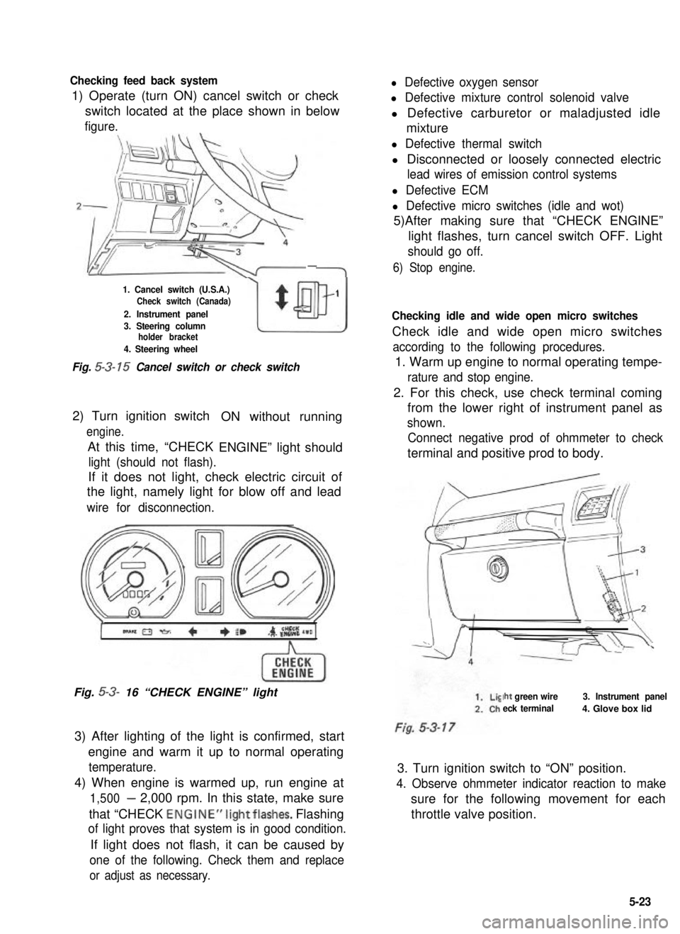
Checking feed back system
1) Operate (turn ON) cancel switch or check
l Defective oxygen sensor
l Defective mixture control solenoid valve
switch located at the place shown in belowl Defective carburetor or maladjusted idle
figure.mixture
-
1. Cancel switch (U.S.A.)Check switch (Canada)
2. Instrument panel
w
$
1
3. Steering columnholder bracket
4. Steering wheel
Fig. 5-3- 15 Cancel switch or check switch
2) Turn ignition switch
engine.
At this time, “CHECK
ON without running
ENGINE” light should
light (should not flash).
If it does not light, check electric circuit of
the light, namely light for blow off and lead
wire for disconnection.
Fig. 5-3- 16 “CHECK ENGINE” light
3) After lighting of the light is confirmed, start
engine and warm it up to normal operating
temperature.
4) When engine is warmed up, run engine at
1,500- 2,000 rpm. In this state, make sure
that “CHECK ENGINE”lightflashes. Flashing
of light proves that system is in good condition.
If light does not flash, it can be caused by
one of the following. Check them and replace
or adjust as necessary.
l Defective thermal switch
l Disconnected or loosely connected electric
lead wires of emission control systems
l Defective ECM
l Defective micro switches (idle and wot)
5)After making sure that “CHECK ENGINE”
light flashes, turn cancel switch OFF. Light
should go off.
6) Stop engine.
Checking idle and wide open micro switches
Check idle and wide open micro switches
according to the following procedures.
1. Warm up engine to normal operating tempe-
rature and stop engine.
2. For this check, use check terminal coming
from the lower right of instrument panel as
shown.
Connect negative prod of ohmmeter to check
terminal and positive prod to body.
Iht green wire
eck terminal
3. Instrument panel
4. Glove box lid
3. Turn ignition switch to “ON” position.
4. Observe ohmmeter indicator reaction to make
sure for the following movement for each
throttle valve position.
5-23
Page 208 of 962
![SUZUKI GRAND VITARA 1987 Service Repair Manual 7-4. REMOVAL AND INSTALLATION
Removal
[Heater and blower motor]
1. Disconnect battery negative cable.
2. Drain cooling system.
WARNING:
To help avoid the danger of being burned, do
not remove the drai SUZUKI GRAND VITARA 1987 Service Repair Manual 7-4. REMOVAL AND INSTALLATION
Removal
[Heater and blower motor]
1. Disconnect battery negative cable.
2. Drain cooling system.
WARNING:
To help avoid the danger of being burned, do
not remove the drai](/manual-img/20/57437/w960_57437-207.png)
7-4. REMOVAL AND INSTALLATION
Removal
[Heater and blower motor]
1. Disconnect battery negative cable.
2. Drain cooling system.
WARNING:
To help avoid the danger of being burned, do
not remove the drain plug and the radiator
cap while the engine and radiator are still hot.
Scalding fluid and steam can be blown out
under pressure if the plug and cap are taken
off too soon.
Fig 7-51. Drain plug2. Radiator
3. Disconnect heater inlet and outlet hoses
from heater unit pipes.
4. Remove instrument panel ass’y with speedo-
meter ass’y as follows.
1) Take off horn pad and remove steering
wheel using special tool @.
2) If equipped with radio and cigarette lighter,
disconnect radio and cigarette lighter lead
wires, and pull out radio case with radio
and cigarette lighter after loosening case
stay screw, and remove radio case bracket.
3) Pull out ashtray and loosen ashtray plate
screws.
4) Disconnect front food opening cable from
lock ass’y.
5) Loosen panel box stay screw and hood
opening cable lock nut on back side of
panel box cover.
6) Disconnect lead wires to control lever at
the coupler and heater control cables.
7) Pull out lever knobs and plate, and loosen
lever case screws.
8) Remove defroster and side ventilator hoses.
9) Disconnect lead wires to speedometer and
switches installed instrument panel at the
couplers.
10) Disconnect speedometer cable from speedo-
meter.
11) Release wire harness clamps installed to
instrument panel.
12) Loosen screws securing instrument panel.
13) Remove instrument panel.
NOTE:
l Before removing, recheck to ascertain all
hoses, wire harness, cables and screws are
disconnected from instrument paneL
l When removing heater lever case which is
fitted in steering column holder, be very
careful not to damage it
5. Remove steering column holder after loosen-
ing front door open stopper screws.
Fig. 7-7Fig. 7-6@ Special tool (Steering wheel
remover 09944-360 10)
7-5
Page 209 of 962
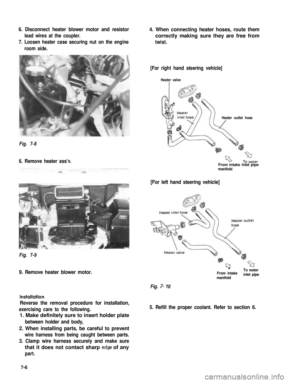
6. Disconnect heater blower motor and resistor
lead wires at the coupler.
7. Loosen heater case securing nut on the engine
room side.
4. When connecting heater hoses, route them
correctly making sure they are free from
twist.
Fig. 7-8
6. Remove heater ass’v.
Fig. 7-9
9. Remove heater blower motor.
Installation
Reverse the removal procedure for installation,
exercising care to the following.
1. Make definitely sure to insert holder plate
between holder and body,
2. When installing parts, be careful to prevent
wire harness from being caught between parts.
3. Clamp wire harness securely and make sure
that it does not contact sharp edge of any
part.
[For right hand steering vehicle]
Heater valve
Heater outlet hose
From intake inlet pipemanifold
[For left hand steering vehicle]
VTo waterFrom intakemanifoldinlet pipe
Fig. 7- 10
5. Refill the proper coolant. Refer to section 6.
7-6
Page 210 of 962
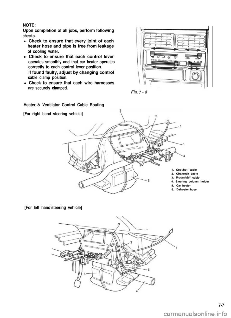
NOTE:
Upon completion of all jobs, perform following
checks.
l Check to ensure that every joint of each
heater hose and pipe is free from leakage
of cooling water.
l Check to ensure that each control lever
operates smoothly and that car heater operates
correctly to each control lever position.
If found faulty, adjust by changing control
cable clamp position.
l Check to ensure that each wire harnessesI
are securely clamped.Ff- -r/g. 7-l 1
Heater & Ventilator Control Cable Routing
[For right hand steering vehicle]
6
1.Cool/hot cable2.Circ/fresh cable3.Room/def. cable4. Steering column holder
5.Car heater6. I Defroster hose
[For left hand’steering vehicle]
7-7
Page 254 of 962
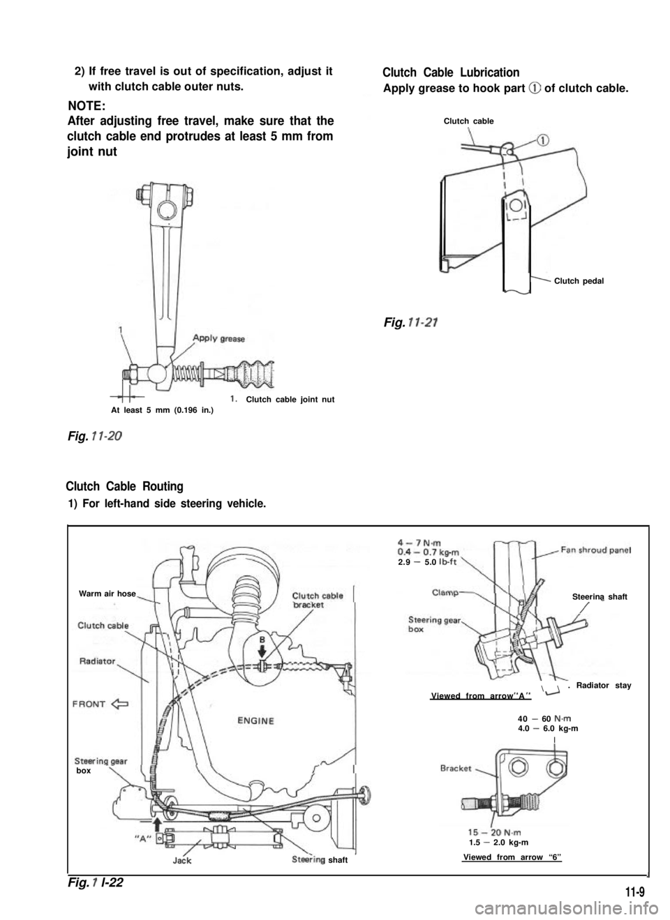
2) If free travel is out of specification, adjust it
with clutch cable outer nuts.
NOTE:
After adjusting free travel, make sure that the
clutch cable end protrudes at least 5 mm from
joint nut
1.Clutch cable joint nutAt least 5 mm (0.196 in.)
Fig. 1 l-20
Clutch Cable Routing
1) For left-hand side steering vehicle.
Clutch Cable Lubrication
Apply grease to hook part @ of clutch cable.
Clutch cable
1 Clutch pedaly-v
Fig. 11-21
Warm air hose
box -
Jadk
15-i0N.m1.5 - 2.0 kg-m
SteeTing shaft’Viewed from arrow “6”
4-7N.m
2.9- 5.0lb-ft
Steerina shaft
/ -
\. Radiator stayI, ,IViewed from arrow A-
40 - 60 N.m4.0 - 6.0 kg-m
I
Fig. 1 l-221
11-9