Page 425 of 962

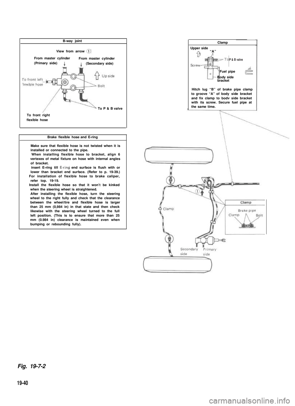
B-way joint
View from arrow @
From master cylinderFrom master cylinder(Primary side)4(Secondary side)
To P & B valve
To front rightflexible hose
Brake flexible hose and E-ring
Make sure that flexible hose is not twisted when it isinstalled or connected to the pipe.When installing flexible hose to bracket, align 6vertexes of metal fixture on hose with internal anglesof bracket.insert E-ring till Ewing end surface is flush with orlower than bracket end surface. (Refer to p. 19-39.) For installation of flexible hose to brake caliper,refer top. 19-19. Install the flexible hose so that it won’t be kinkedwhen the steering wheel is straightened.After installing the flexible hose, turn the steeringwheel to the right fully and check that the clearancebetween the wheel/tire and flexible hose is largerthan 25 mm (0,984 in) in that state and then checklikewise with the steering wheel turned to the fullleft position. (This is to ensure that more than 25mm (0.984 in) clearance is maintained even whenbumping or rebounding fully).
Clamp
Upper sideA“A”71’/
sre~~To
Tr
Fuel pipe0Body sidebracket
Hitch lug “B” of brake pipe clampto groove “A” of body side bracketand fix clamp to bodv side bracketwith its screw. Secure fuel pipe atthe same time.
Fig. 19-7-2
19-40
P & B valve
Page 450 of 962

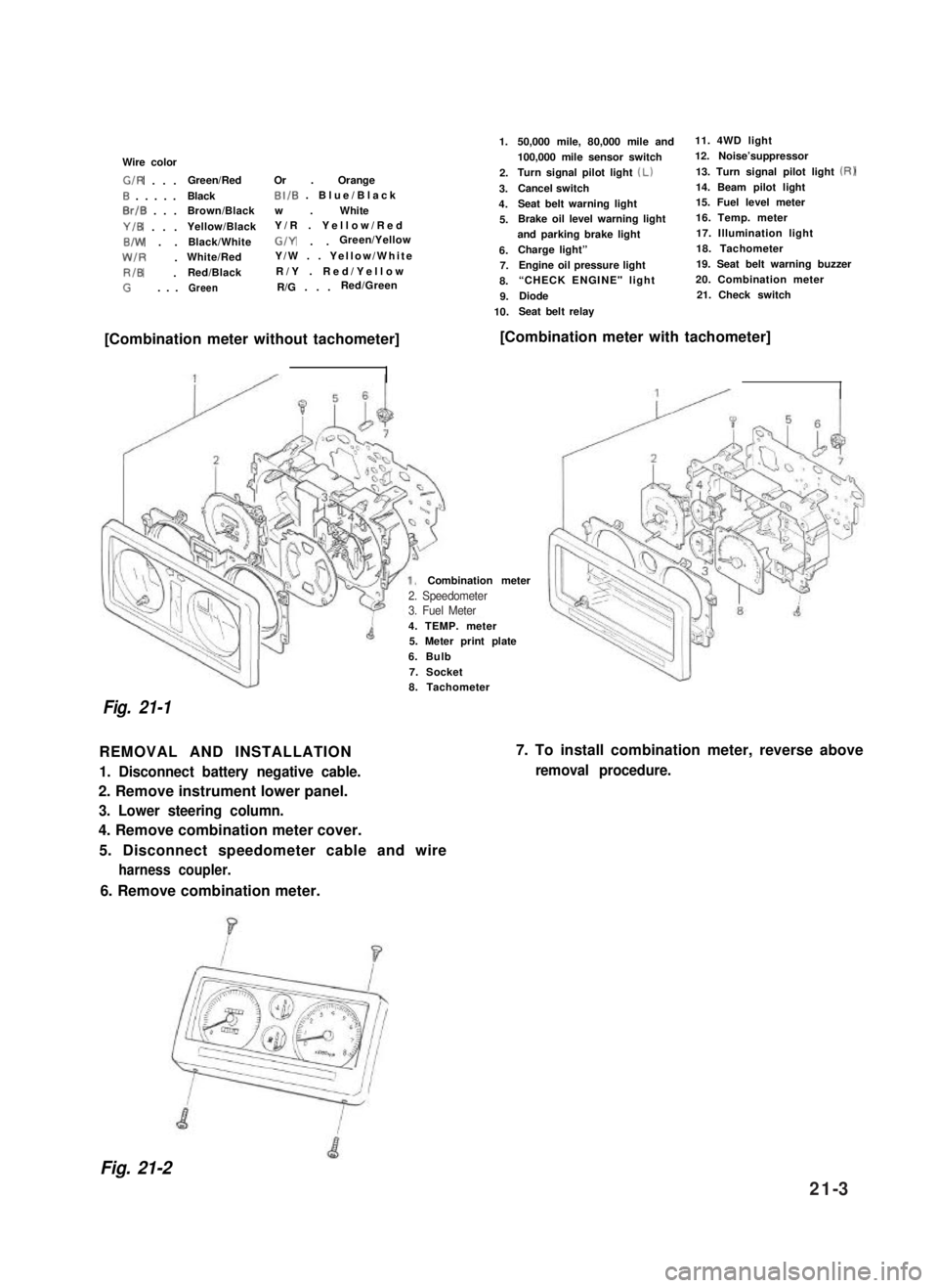
Wire color
G/R . . .Green/RedOr . Orange
0 . . . . .BlackBI/B . Blue/Black
0rlB . . .Brown/Blackw . White
Y/B . . .Yellow/BlackY/R . Yellow/Red
B/W . .Black/WhiteG/Y . .Green/Yellow
W/R .White/RedY/W . . Yellow/White
RIB .Red/BlackR/Y . Red/Yellow
G. . .GreenR/G . . .Red/Green
1.
2.
3.
4.
5.
6.7.
8.
9.
10.
50,000 mile, 80,000 mile and11. 4WD light
100,000 mile sensor switch12. Noise’suppressor
Turn signal pilot light (Lb13. Turn signal pilot light (RI
Cancel switch14. Beam pilot light
Seat belt warning light15. Fuel level meter
Brake oil level warning light16. Temp. meter
and parking brake light17. Illumination light
Charge light”18. Tachometer
Engine oil pressure light19. Seat belt warning buzzer
“CHECK ENGINE" light 20. Combination meter
Diode21. Check switch
Seat belt relay
[Combination meter without tachometer][Combination meter with tachometer]
4. TEMP. meter5. Meter print plate
6. Bulb
7. Socket
Combination meter
Fig. 21-1
8. Tachometer
REMOVAL AND INSTALLATION
1. Disconnect battery negative cable.
2. Remove instrument lower panel.
3. Lower steering column.
4. Remove combination meter cover.
5. Disconnect speedometer cable and wire
harness coupler.
7. To install combination meter, reverse above
removal procedure.
6. Remove combination meter.
Fig. 21-2
2. Speedometer3. Fuel Meter
21-3
Page 469 of 962
1.Instrument panel
2.Steering column
3. Steering column holder4.Wiring harness No.1
5. To combination switch
6. To ignition switch
7. To clutch switch
8. Defroster hose9. Brake pedal
10. Clutch pedal
11. Clamp lead wires of ignition switch and combination switch,using care not to allow lead wires to contact the edge of steer-
ing column bracket.
Fig. 21-41
21-16. WIRING DIAGRAM
Wiring diagrams are attached at the end of this manual.
21-22
Page 472 of 962
Convertible/Hard Top
WHEEL AND SUSPENSIONI
Tire size: front and rear1 P205/70 R15I
Tire pressurefront
rear
Suspension typefront
rear
140 kPa (1.40 kg/cm’, 20 psi)
140 kPa (1.40 kg/cm’, 20 psi)-unladen
180 kPa (1.80 kg/cm*, 26 psi)-laden
Leaf spring
Leaf spring
STEERING
Turning radius1 5.1 m (16.7ft)
1 Steering gear box1Ball nut typeI
Toe-in
Camber angle
Caster angle
King pin angle
BRAKE SYSTEM
Type
Wheel brake
Parking brake
CAPACITIES
Cooling solution
Fuel tank
2 - 6 mm (0.08 - 0.24 in.)
lo 00’
) 3º 30’I
front
rear
9º 00’
4-wheel, hydraulic
Disc brake (floating caliper type)
Drum brake (leading and trailing)
Mechanical actuated on rear wheels
4.8 Q (10.1/8.4 US/Imp pt)
4OQ (10.6/8.8 US/Imp cral)
Engine oil
Transmission oil
Differential gear
box oil
Transfer gear box oil
front
rear
3.5 II (7.4/6.2 US/Imp pt)
1.3 II (2.7/2.3 US/Imp pt)
2.0 Q (4.2/3.5 US/Imp pt)
1.5 II (3.2/2.6 US/Imp pt)
0.8 !? (1.7/l .4 US/Imp pt)
22-3