1987 SUZUKI GRAND VITARA check engine light
[x] Cancel search: check engine lightPage 141 of 962

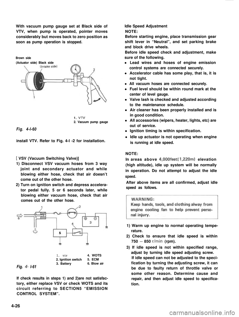
With vacuum pump gauge set at Black side of
VTV, when pump is operated, pointer moves
considerably but moves back to zero position as
soon as pump operation is stopped.
Brown side
(Actuator side) Black side
Fig. 4-l-60
1. VTV
2. Vacuum pump gauge
install VTV. Refer to Fig. 4-l -2 for installation.
[ VSV (Vacuum Switching Valve)]
1) Disconnect VSV vacuum hoses from 3 way
joint and secondary actuator and while
blowing either hose, check that air doesn’t
come out of the other hose.
2) Turn on ignition switch and depress accelera-
tor pedal fully. 5 or 6 seconds later, while
blowing either vacuum hose, check that air
comes out of the other hose.
J5
Fig. 4- l-61
1I
1. vsv4. WOTS
2. Ignition switch5. ECM
3. Battery6. Blow air
If check results in steps 1) and 2)are not satisfac-
tory, either replace VSV or check WOTS and its
circuit referring to SECTION5 “EMISSION
CONTROL SYSTEM”.
Idle Speed Adjustment
NOTE:
Before starting engine, place transmission gear
shift lever in “Neutral”, and set parking brake
and block drive wheels.
Before idle speed check and adjustment, make
sure of the following.
l Lead wires and hoses of engine emission
control systems are connected securely.
l Accelerator cable has some play, that is, it is
not tight.
l All vacuum hoses are connected securely.
l Fuel level should be within round mark at the
center of level gauge.
l Valve lash is checked and adjusted according
to the maintenance schedule.
l Air cleaner has been properly installed and is
in good condition.
l All accessories (wipers, heater, lights, etc) are
out of service.
l Ignition timing is within specification.
l Idle up actuator is not operating when engine
is running at idle speed.
NOTE:
In areas above 4,00Ofeet( 1,220m) elevation
(high altitude), idle up system will be normally
in operation. Do not attempt to adjust the idle
speed.
After above items are all confirmed, adjust idle
speed as follows.
1) Warm up engine to normal operating tempe-
rature.
2) Check to ensure that idle speed is within
750 - 850 r/min (rpm).
3) If idle speed is not within specified range,
adjust by turning idle speed adjusting screw.
If idle speed can not be adjusted to the speci-
fication by turning the adjusting screw, it can
be due to faulty return of throttle valve or
some other reason. Determine cause and
repair, and then adjust idle speed to specifica-
tion.
4-26
Page 142 of 962

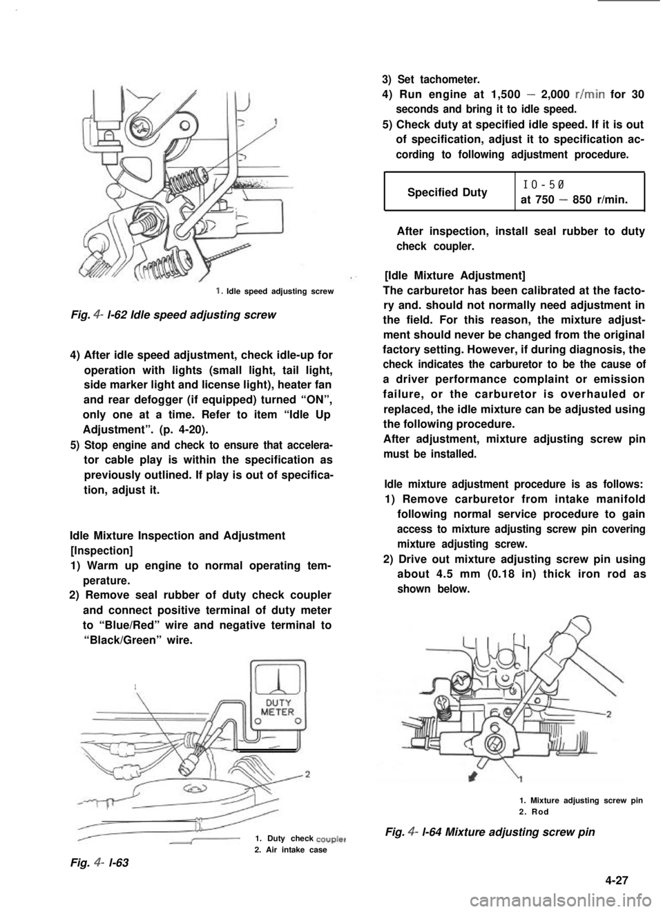
1. Idle speed adjusting screw
Fig. 4- l-62 Idle speed adjusting screw
4) After idle speed adjustment, check idle-up for
operation with lights (small light, tail light,
side marker light and license light), heater fan
and rear defogger (if equipped) turned “ON”,
only one at a time. Refer to item “Idle Up
Adjustment”. (p. 4-20).
5) Stop engine and check to ensure that accelera-
tor cable play is within the specification as
previously outlined. If play is out of specifica-
tion, adjust it.
Idle Mixture Inspection and Adjustment
[Inspection]
1) Warm up engine to normal operating tem-
perature.
2) Remove seal rubber of duty check coupler
and connect positive terminal of duty meter
to “Blue/Red” wire and negative terminal to
“Black/Green” wire.
1
1. Duty check
3) Set tachometer.
4) Run engine at 1,500 - 2,000 r/min for 30
seconds and bring it to idle speed.
5) Check duty at specified idle speed. If it is out
of specification, adjust it to specification ac-
cording to following adjustment procedure.
Specified DutyIO-50
at 750 - 850 r/min.
After inspection, install seal rubber to duty
check coupler.
[Idle Mixture Adjustment]
The carburetor has been calibrated at the facto-
ry and. should not normally need adjustment in
the field. For this reason, the mixture adjust-
ment should never be changed from the original
factory setting. However, if during diagnosis, the
check indicates the carburetor to be the cause of
a driver performance complaint or emission
failure, or the carburetor is overhauled or
replaced, the idle mixture can be adjusted using
the following procedure.
After adjustment, mixture adjusting screw pin
must be installed.
Idle mixture adjustment procedure is as follows:
1) Remove carburetor from intake manifold
following normal service procedure to gain
access to mixture adjusting screw pin covering
mixture adjusting screw.
2) Drive out mixture adjusting screw pin using
about 4.5 mm (0.18 in) thick iron rod as
shown below.
1. Mixture adjusting screw pin2. Rod
Fig. 4- l-64 Mixture adjusting screw pin
2. Air intake case
Fig. 4- l-63
4-27
Page 143 of 962

3) Reinstall carburetor following normal service
procedures.
Connect emission control system hoses and
lead wires. Make specified play on accelerator
cable and refill cooling system.
4) Place transaxle gear shift lever in “Neutral”,
set parking brake and block drive wheels.
5) Start engine, and warm it up to normal
operating temperature, stop engine.
6) Be sure to check the following before idle
mixture adjustment.
l Fuel level is within round mark at the
center of level gauge.
l Valve lash is checked and adjusted accord-
ing to the maintenance schedule.
l Air cleaner has been properly installed
and is in good condition.
l All accessories (wipers, heater, lights etc)
are out of service.
l Ignition timing is within specification.
l Choke valve opens fully.
l Idle-up actuator does not operate.
7) Check and adjust idle speed to specification
if necessary.
8) Remove seal rubber of duty check coupler
and connect positive terminal of duty
meter to“Blue/Red” wire and negative
terminal to “Black/Green” wire.
9) Run engine at 1,500 - 2,000 r/min for 30
seconds and bring it to idle speed.
10) With engine running at idle speed, adjust idle
mixture adjusting screw slowly in small incre-
ment allowing time for duty to stabilize after
turning screw to obtain duty of 10 - 50.
If duty is too low, back screw out; if too
high, screw it in. After obtaining duty of
10 - 50, recheck idle speed, and adjust if
necessary.
NOTE:
If adjustment can’t be made because duty meter
indicator does not deflect, check feed back
system according to the checking procedure of
system described in section of Emission Control
System.
11) After adjustment, install seal rubber to duty
check coupler and drive in idle mixture
adjusting screw pin.
4-28
Page 167 of 962

EGR DIAGNOSIS
Condition
Engine idles abnormally rough
and/or stalls.
Possible CauseCorrection
EGR valve vacuum hoses mis-Check EGR valve vacuum hose routing.
routed.Correct as required.
Leaking EGR valve.Check EGR valve for correct operation.
EGR valve gasket failed or looseCheck EGR attaching bolts for tightness.
EG R attaching bolts.If no loose, remove EGR valve and inspect
gasket.
Improper vacuum to EGR valveCheck vacuum from carburetor EGR port with
at idle.engine at stabilized operating temperature and
at idle speed.
Engine runs rough on light
throttle acceleration and has
poor part load performance.
Sticky EGR valve
EGR valve vacuum hose mis-
routed.
Loose EGR attaching bolts
Sticky or binding EGR valve.
Check EGR valve for correct operation,
Check EGR valve vacuum hose routing.
Correct as required.
Torque bolts.
Same as listing in “Engine idles Abnomrally
Rough and/or Stalls” condition.
Clean EGR passage deposits.
Perform EGR System Check.
EGR modulator valve blocked
or air flow restricted.
Check EGR modulator valve operation.
Engine stalls on decelerations.
Wrong or no EGR gasket.
EGR modulator valve blocked
of air flow restricted.
Install new gasket, torque attaching parts.
Check EGR modulator valve operation.
Restriction in EGR vacuum line.Check EGR vacuum lines for kinks, bends, etc.
Remove or replace hoses as required.
VSV filter plugged.
Sticking or binding EGR valve.
Check VSV for correct operation.
Check EGR valve for excessive deposits causing
sticky or binding operation.
Part throttle engine detonation.EGR modulator valve blockedCheck internal control valve operation.
of air flow restricted.
NOTE:
Non-functioning EGR valveInsufficient exhaust gas recircu-Check EGR valve hose routing. Check EGR
could contribute to partlation flow during part throttlevalve operation. Repair or replace as required.
throttle detonation. Detonationaccelerations.Replace valve as required. Check EGR passages
can be caused by several otherand valve for excessive deposit.
engine variables. Perform igni-Clean as required. Check VSV operation.
tion and carburetor related
diagnosis.
5-16
Page 172 of 962
![SUZUKI GRAND VITARA 1987 Service Repair Manual [Hoses]
Visually inspect hoses and pipe for cracks,
damage, or excessive bends, and hose connec-
tion for tightness.
Fig. 5-3-9
HOT IDLE COMPENSATOR (HIC)
Checking Hot Idle Compensator
1) Remove air i SUZUKI GRAND VITARA 1987 Service Repair Manual [Hoses]
Visually inspect hoses and pipe for cracks,
damage, or excessive bends, and hose connec-
tion for tightness.
Fig. 5-3-9
HOT IDLE COMPENSATOR (HIC)
Checking Hot Idle Compensator
1) Remove air i](/manual-img/20/57437/w960_57437-171.png)
[Hoses]
Visually inspect hoses and pipe for cracks,
damage, or excessive bends, and hose connec-
tion for tightness.
Fig. 5-3-9
HOT IDLE COMPENSATOR (HIC)
Checking Hot Idle Compensator
1) Remove air intake case with hose.
2) Check temperature around HIC with thermo-
meter.
3) If temperature is below 45°C (113” F), air
should not come out of HIC when air is
blown into hose. If temperature is above
65°C (149” F), air comes out of HIC.
Replace H IC if defective.
4) After checking, install air intake case and
connect hose to intake manifold.
NOTE:
l To check HIC for operation at higher than
65°C (149°F) temperature when HIC (bi-
metal) temperature is lower than 45°C
(113”F), warm it up with hair drier or photo
light before checking.
l Never touch bimetal or valve in HIC.
1
Below 45°C (113’F)Above 65’C (149’F)
Fig.5-i- 10
DECELERATION MIXTURE CONTROL
SYSTEM
Checking
[Hoses]
Inspect each hose for pinholes, cracks or damage.
Also check to ensure that each joint is securely
connected. Any part found defective must be
corrected or replaced.
.
Fig. 5-3- 11
[Mixture control valve (MCV)]
1) Warm up the engine to normal operating
temperature.
2) Disconnect hose @ and reconnect it. At this
time, check that air is drawn into MCV.
NOTE:
At this time, the engine will idle rough or die,
but this is normal.
A piece of paper
If the above checks show anything wrong,
replace it.
5-21
Page 173 of 962

[Jet1
1) Remove jet.
2) When blowing air into pipe 0, air should
come out of pipe 0.
Replace clogged jet.
3) Install jet with its gray side directed toward
MCV.
1. Pipe (Gray side)2.Pipe
33.Jet
Fig.53-134.Blowair
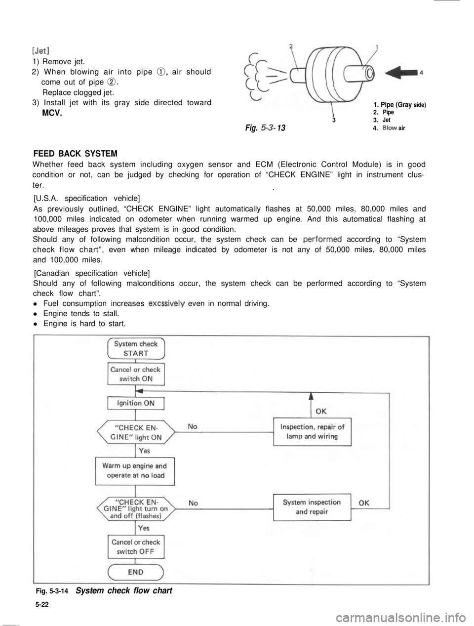
FEED BACK SYSTEM
Whether feed back system including oxygen sensor and ECM (Electronic Control Module) is in good
condition or not, can be judged by checking for operation of “CHECK ENGINE” light in instrument clus-
ter..
[U.S.A. specification vehicle]
As previously outlined,“CHECK ENGINE” light automatically flashes at 50,000 miles, 80,000 miles and
100,000 miles indicated on odometer when running warmed up engine. And this automatical flashing at
above mileages proves that system is in good condition.
Should any of following malcondition occur, the system check can be .performed according to “System
check flow chart”,even when mileage indicated by odometer is not any of 50,000 miles, 80,000 miles
and 100,000 miles.
[Canadian specification vehicle]
Should any of following malconditions occur, the system check can be performed according to “System
check flow chart”.
l Fuel consumption increases excssively even in normal driving.
l Engine tends to stall.
l Engine is hard to start.
System check
STARTI
Cancel or check
switch ON
“CHECK EN-
Yes
Inspection, repair of
lamp and wiring1
Warm up engine and
operate at no load
I
“CHECK EN-GINE”light turnonand off (flashes)I
NoSystem inspection OK
and repair
Cancel or check
Fig. 5-3-14System check flow chart
5-22
Page 174 of 962

Checking feed back system
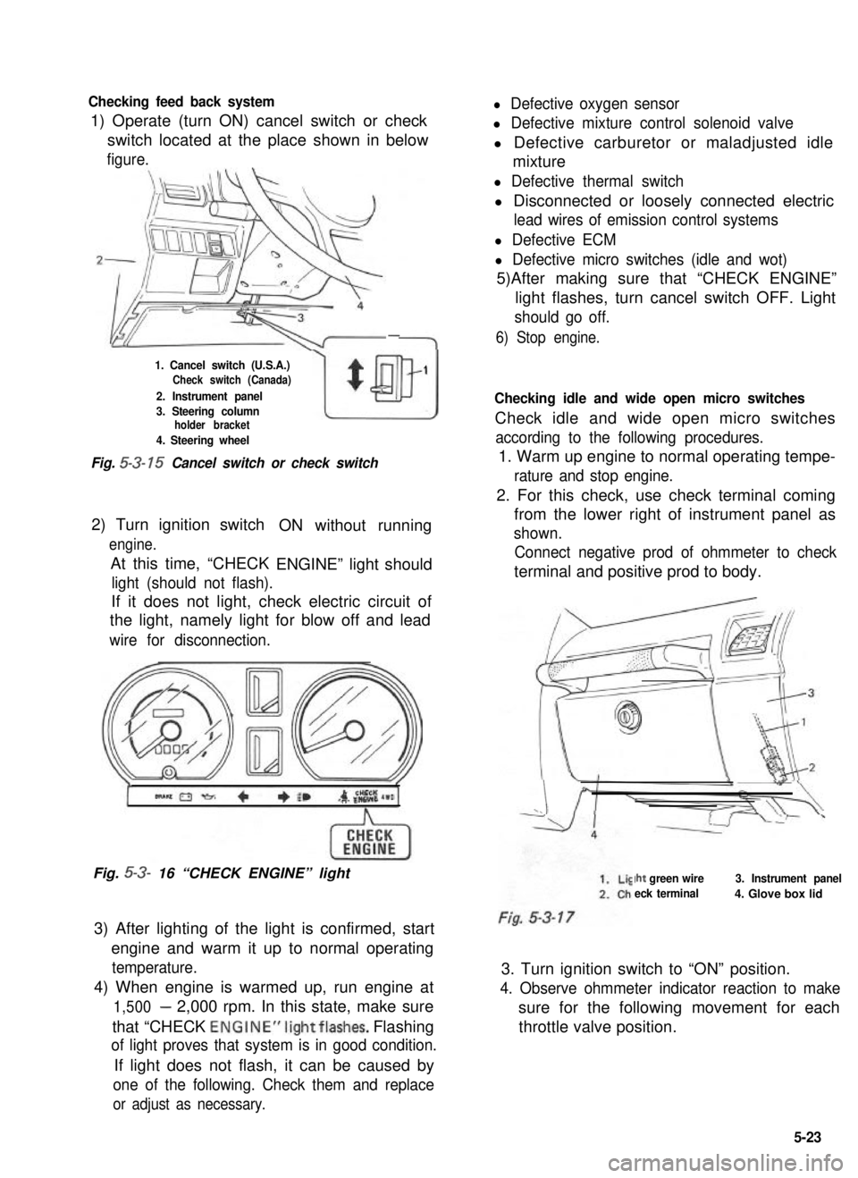
1) Operate (turn ON) cancel switch or check
l Defective oxygen sensor
l Defective mixture control solenoid valve
switch located at the place shown in belowl Defective carburetor or maladjusted idle
figure.mixture
-
1. Cancel switch (U.S.A.)Check switch (Canada)
2. Instrument panel
w
$
1
3. Steering columnholder bracket
4. Steering wheel
Fig. 5-3- 15 Cancel switch or check switch
2) Turn ignition switch
engine.
At this time, “CHECK
ON without running
ENGINE” light should
light (should not flash).
If it does not light, check electric circuit of
the light, namely light for blow off and lead
wire for disconnection.
Fig. 5-3- 16 “CHECK ENGINE” light
3) After lighting of the light is confirmed, start
engine and warm it up to normal operating
temperature.
4) When engine is warmed up, run engine at
1,500- 2,000 rpm. In this state, make sure
that “CHECK ENGINE”lightflashes. Flashing
of light proves that system is in good condition.
If light does not flash, it can be caused by
one of the following. Check them and replace
or adjust as necessary.
l Defective thermal switch
l Disconnected or loosely connected electric
lead wires of emission control systems
l Defective ECM
l Defective micro switches (idle and wot)
5)After making sure that “CHECK ENGINE”
light flashes, turn cancel switch OFF. Light
should go off.
6) Stop engine.
Checking idle and wide open micro switches
Check idle and wide open micro switches
according to the following procedures.
1. Warm up engine to normal operating tempe-
rature and stop engine.
2. For this check, use check terminal coming
from the lower right of instrument panel as
shown.
Connect negative prod of ohmmeter to check
terminal and positive prod to body.
Iht green wire
eck terminal
3. Instrument panel
4. Glove box lid
3. Turn ignition switch to “ON” position.
4. Observe ohmmeter indicator reaction to make
sure for the following movement for each
throttle valve position.
5-23
Page 183 of 962
![SUZUKI GRAND VITARA 1987 Service Repair Manual [Checking sensors and their lead wires]
The sensors constituting the feed back system are; wide open micro switch, idle micro switch, thermal
switch, high altitude compensator, thermal engine room swi SUZUKI GRAND VITARA 1987 Service Repair Manual [Checking sensors and their lead wires]
The sensors constituting the feed back system are; wide open micro switch, idle micro switch, thermal
switch, high altitude compensator, thermal engine room swi](/manual-img/20/57437/w960_57437-182.png)
[Checking sensors and their lead wires]
The sensors constituting the feed back system are; wide open micro switch, idle micro switch, thermal
switch, high altitude compensator, thermal engine room switch and fifth switch. If any of the above
sensors malfunctions or if the sensor circuit has some trouble, signals are not sent to the ECM and conse-
quently the feed back system will not function properly.
Therefore, check each sensor and its circuit according to the following procedure.
1) Turn OFF the ignition switch.
2) Disconnect the coupler from the ECM.
3) Connect the ohmmeter between the terminal @ of the disconnected coupler and the terminal @
(ground) as shown in below figure and measure the resistance. And then repeat the same with each of
the terminals 0, @I, @I, @ and @I.
1. Coupler (Viewed from wireharness side)
2. Wide open micro switch3. idle micro switch
4. Thermal switch
5. Thermal engine room switch6. Fifth switch
7. High altitude compensator
8. Gr/R (Gray/Red) lead wire9. Gr/Y (Gray/Yellow) lead wire10. 81 (Blue) lead wire
11. P/B (Pink/Black) lead wire
12. Gr/B (Gray/Black) lead wire
13. Lg/R (Light green/Red) lead wire
14. B/G (Black/Green) lead wire
Fig. 5-3-43 Checking sensors and their circuits
4) If each ohmmeter reading is as given below, the sensor and its circuit are in good condition. But if not,
the sensor itself may be defective or the lead wire disconnected or out of contact. After checking,
connect the coupler to ECM securely.
Idle micro switch
High altitude compensator
Thermal engine room switch
Wide open micro switch
1 Fifth switch
Ohmmeter
Terminal reading (S2)Condition
When coolant temp. is low.
When coolant temp. is above 46.5’C (I 16’F).
0 1
When engine is warm and accelerator pedal is not depressed.
When accelerator pedal is depressed a little.
00
@
When altitude is below 1,220 m (4,000 ft.).
0When altitude is above 1,220 m (4,000 ft.).
0
When temp. in engine room is low.
When temp. in engine room is above 19.5’C (67°F).
0When accelerator pedal is not depressed or depressed only a
0little.
CoWhen accelerator pedal is depressed all the way.
@ Oa
When gear shift lever is shifted to low, second, third, forth or
reverse gear position.
0When gear shift lever is shifted to fifth gear position.
5-32