1987 SUZUKI GRAND VITARA check engine light
[x] Cancel search: check engine lightPage 184 of 962
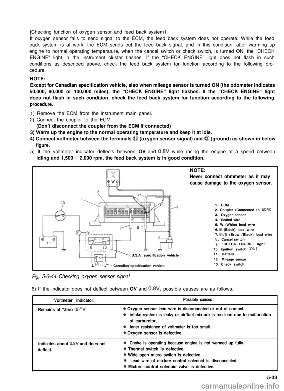
[Checking function of oxygen sensor and feed back system1
If oxygen sensor fails to send signal to the ECM, the feed back system does not operate. While the feed
back system is at work, the ECM sends out the feed back signal, and in this condition, after warming up
engine to normal operating temperature, when the cancel switch or check switch, is turned ON, the “CHECK
ENGINE” light in the instrument cluster flashes. If the “CHECK ENGINE” light does not flash in such
conditions as described above, check the feed back system for function according to the following pro-
cedure.
NOTE:
Except for Canadian specification vehicle, also when mileage sensor is turned ON (the odometer indicates
50,000, 80,000 or 100,000 miles), the “CHECK ENGINE” light flashes. If the “CHECK ENGINE” light
does not flash in such condition, check the feed back system for function according to the following
procedure.
1) Remove the ECM from the instrument main panel.
2) Connect the coupler to the ECM..
(Don’t disconnect the coupler from the ECM if connected)
3) Warm up the engine to the normal operating temperature and keep it at idle.
4) Connect voltmeter between the terminals @I (oxygen sensor signal) and @ (ground) as shown in below
figure.
5) If the voltmeter indicator deflects between OV and 0.8V while racing the engine at a speed between
idling and 1,500 - 2,000 rpm, the feed back system is in good condition.
Fig,
NOTE:
Never connect ohmmeter as it may
cause damage to the oxygen sensor.
U.S.A. specification vehicle
1.ECM2. Coupler (Connected to ECM)
3.Oxygen sensor
4.Sealed wire5. W (White) lead wire
6. I3 (Black) lead wire7. Br/B (Brown/Black) lead wire8.Cancel switch9.“CHECK ENGINE” light
10. Ignition switch (ON)11.Battery
12.Mileage sensor115 'L----JA Canadian specification vehicle
I 5-3-44 Checking oxygen sensor signal
13. Check switch
6) If the indicator does not deflect between OV and 0.8V, possible causes are as follows.
Voltmeter indicator:
Remains at “Zero (0)“V
Possible causes
0 Oxygen sensor lead wire is disconnected or out of contact.
0intake system is leaky or air/fuel mixture is too lean due to malfunction
of carburetor,
0Inner resistance of voltmeter is too small.
0 Oxygen sensor is defective.
Indicates about 0.8V and does not
deflect.
0Choke is operating because engine is not warmed up fully.
0 Thermal switch is defective.
0 Wide open micro switch is defective.
0Lead wire of mixture control solenoid is disconnected.
0 Mixture control solenoid valve is defective.
5-33
Page 185 of 962
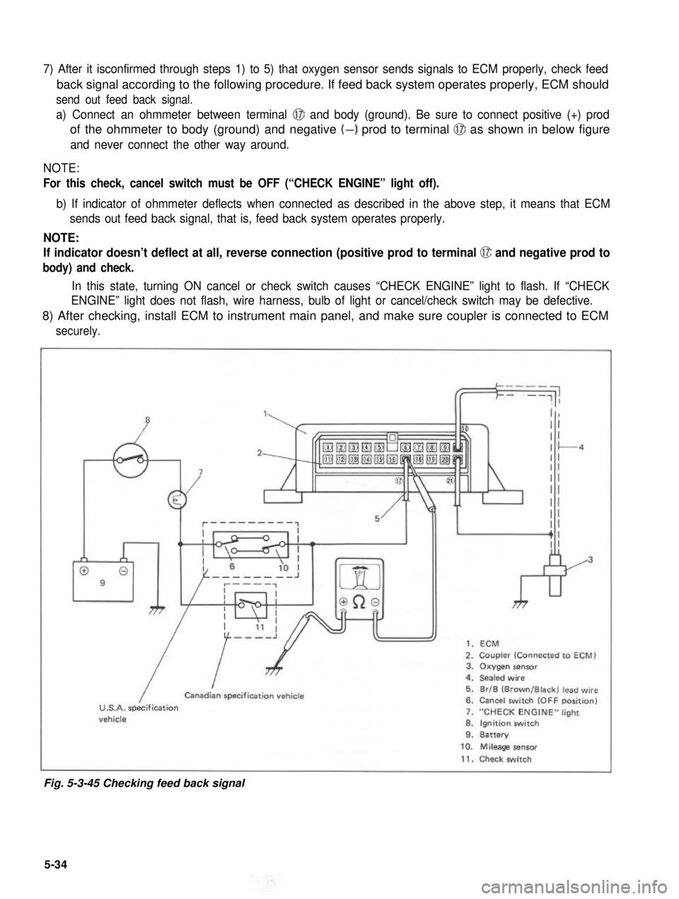
7) After it isconfirmed through steps 1) to 5) that oxygen sensor sends signals to ECM properly, check feed
back signal according to the following procedure. If feed back system operates properly, ECM should
send out feed back signal.
a) Connect an ohmmeter between terminal @I and body (ground). Be sure to connect positive (+) prod
of the ohmmeter to body (ground) and negative (-) prod to terminal @J as shown in below figure
and never connect the other way around.
NOTE:
For this check, cancel switch must be OFF (“CHECK ENGINE” light off).
b) If indicator of ohmmeter deflects when connected as described in the above step, it means that ECM
sends out feed back signal, that is, feed back system operates properly.
NOTE:
If indicator doesn’t deflect at all, reverse connection (positive prod to terminal @ and negative prod to
body) and check.
In this state, turning ON cancel or check switch causes “CHECK ENGINE” light to flash. If “CHECK
ENGINE” light does not flash, wire harness, bulb of light or cancel/check switch may be defective.
8) After checking, install ECM to instrument main panel, and make sure coupler is connected to ECM
securely.
”1,
009
7
kr
1. ECM
2. Coupler (Connected to ECM)3. Oxygen sensor4. Sealed wire
5. Br/B (Brown/Black) lead wire6. Cancel switch (OFF position)
7. “CHECK ENGINE” light
8. Ignition switch9. Battery
/
ICanadian specification vehicle
U.S.A. specificationvehicle
10. Mileage sensor
11. Check switch
Fig. 5-3-45 Checking feed back signal
5-34
Page 186 of 962
![SUZUKI GRAND VITARA 1987 Service Repair Manual [Checking idle-up signal]
The idle-up system operates when any of the small lights (such as tail light, side marker light and license
light), heater fan and rear defogger is put in operation. If the i SUZUKI GRAND VITARA 1987 Service Repair Manual [Checking idle-up signal]
The idle-up system operates when any of the small lights (such as tail light, side marker light and license
light), heater fan and rear defogger is put in operation. If the i](/manual-img/20/57437/w960_57437-185.png)
[Checking idle-up signal]
The idle-up system operates when any of the small lights (such as tail light, side marker light and license
light), heater fan and rear defogger is put in operation. If the idle-up actuator fails to operate even when
any of such equipments is put in operation, check if signal is sent to the ECM according to the following
procedure.
1) Disconnect the coupler from the ECM.
2) Turn ON the ignition switch but don’t run the engine.
3) Connect a voltmeter between the @ terminal and the body (ground) as shown in below figure. If the
voltmeter indicates 11 - 14V when each equipment is operated individually, it means that idle-up
signal is sent to the ECM.
If the voltmeter does not indicate 11- 14V, the particular circuit is disconnected or in poor contact.
Check the circuit for such conditions.
4) After checking, connect the coupler to ECM securely.
1.Coupler
2. 3.Small Heater lights fan
4. Rear defogger (if equipped)5. Ignition switch (ON)6. Battery
7. Br/Y (Brown/Yellow)
4
&
lead wire
Fig. 5-3-46 Checking idle-up signal
5-35
Page 193 of 962
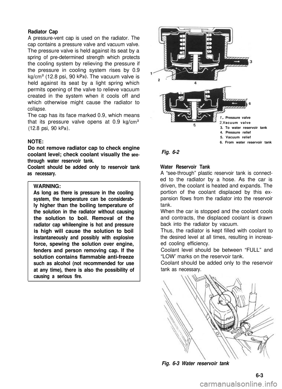
Radiator Cap
A pressure-vent cap is used on the radiator. The
cap contains a pressure valve and vacuum valve.
The pressure valve is held against its seat by a
spring of pre-determined strength which protects
the cooling system by relieving the pressure if
the pressure in cooling system rises by 0.9
kg/cm2 (12.8 psi, 90 kPa). The vacuum valve is
held against its seat by a light spring which
permits opening of the valve to relieve vacuum
created in the system when it cools off and
which otherwise might cause the radiator to
collapse.
The cap has its face marked 0.9, which means
that its pressure valve opens at 0.9 kg/cm2
(12.8 psi, 90 kPa).
NOTE:
Do not remove radiator cap to check engine
coolant level; check coolant visually the see-
through water reservoir tank.
Coolant should be added only to reservoir tank
as necessary.
4
WARNING:
As long as there is pressure in the cooling
system, the temperature can be considerab-
ly higher than the boiling temperature of
the solution in the radiator without causing
the solution to boil. Removal of the
radiator cap whileengine is hot and pressure
is high will cause the solution to boil
instantaneously and possibly with explosive
force, spewing the solution over engine,
fenders and person removing cap. If the
solution contains flammable anti-freeze
such as alcohol (not recommended for use
at any time), there is also the possibility of
causing a serious fire.
2’
I6
. Pressure valve
Vacuum valve
3. To water reservoir tank4. Pressure relief5. Vacuum relief
6. From water reservoir tank
Fig. 6-2
Water Reservoir Tank
A “see-through” plastic reservoir tank is connect-
ed to the radiator by a hose. As the car is
driven, the coolant is heated and expands. The
portion of the coolant displaced by this ex-
pansion flows from the radiator into the reservoir
tank.
When the car is stopped and the coolant cools
and contracts, the displaced coolant is drawn
back into the radiator by vacuum.
Thus, the radiator is kept filled with coolant to
the desired level at all times, resulting in increas-
ed cooling efficiency.
Coolant level should be between “FULL” and
“LOW’ marks on the reservoir tank.
Coolant should be added only to the reservoir
tank as necessary.
Fig. 6-3 Water reservoir tank
6-3
Page 208 of 962
![SUZUKI GRAND VITARA 1987 Service Repair Manual 7-4. REMOVAL AND INSTALLATION
Removal
[Heater and blower motor]
1. Disconnect battery negative cable.
2. Drain cooling system.
WARNING:
To help avoid the danger of being burned, do
not remove the drai SUZUKI GRAND VITARA 1987 Service Repair Manual 7-4. REMOVAL AND INSTALLATION
Removal
[Heater and blower motor]
1. Disconnect battery negative cable.
2. Drain cooling system.
WARNING:
To help avoid the danger of being burned, do
not remove the drai](/manual-img/20/57437/w960_57437-207.png)
7-4. REMOVAL AND INSTALLATION
Removal
[Heater and blower motor]
1. Disconnect battery negative cable.
2. Drain cooling system.
WARNING:
To help avoid the danger of being burned, do
not remove the drain plug and the radiator
cap while the engine and radiator are still hot.
Scalding fluid and steam can be blown out
under pressure if the plug and cap are taken
off too soon.
Fig 7-51. Drain plug2. Radiator
3. Disconnect heater inlet and outlet hoses
from heater unit pipes.
4. Remove instrument panel ass’y with speedo-
meter ass’y as follows.
1) Take off horn pad and remove steering
wheel using special tool @.
2) If equipped with radio and cigarette lighter,
disconnect radio and cigarette lighter lead
wires, and pull out radio case with radio
and cigarette lighter after loosening case
stay screw, and remove radio case bracket.
3) Pull out ashtray and loosen ashtray plate
screws.
4) Disconnect front food opening cable from
lock ass’y.
5) Loosen panel box stay screw and hood
opening cable lock nut on back side of
panel box cover.
6) Disconnect lead wires to control lever at
the coupler and heater control cables.
7) Pull out lever knobs and plate, and loosen
lever case screws.
8) Remove defroster and side ventilator hoses.
9) Disconnect lead wires to speedometer and
switches installed instrument panel at the
couplers.
10) Disconnect speedometer cable from speedo-
meter.
11) Release wire harness clamps installed to
instrument panel.
12) Loosen screws securing instrument panel.
13) Remove instrument panel.
NOTE:
l Before removing, recheck to ascertain all
hoses, wire harness, cables and screws are
disconnected from instrument paneL
l When removing heater lever case which is
fitted in steering column holder, be very
careful not to damage it
5. Remove steering column holder after loosen-
ing front door open stopper screws.
Fig. 7-7Fig. 7-6@ Special tool (Steering wheel
remover 09944-360 10)
7-5
Page 219 of 962
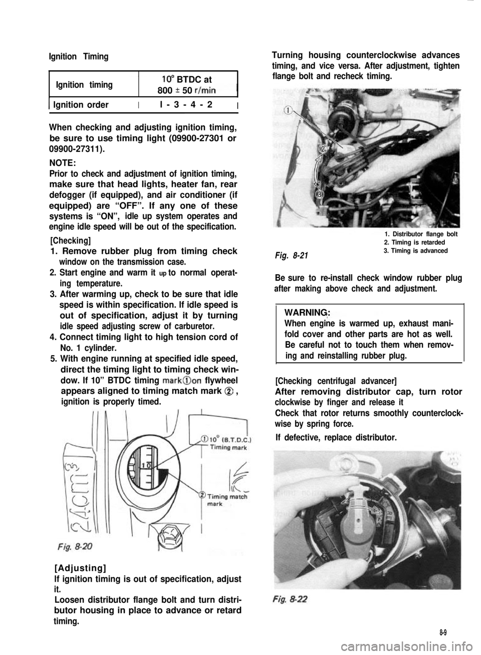
Ignition Timing
Ignition timing10” BTDC at
800 * 50 r/min
1 Ignition orderIl-3-4-2I
When checking and adjusting ignition timing,
be sure to use timing light (09900-27301 or
09900-27311).
NOTE:
Prior to check and adjustment of ignition timing,
make sure that head lights, heater fan, rear
defogger (if equipped), and air conditioner (if
equipped) are “OFF”. If any one of these
systems is “ON”,idle up system operates and
engine idle speed will be out of the specification.
[Checking]
1. Remove rubber plug from timing check
window on the transmission case.
2. Start engine and warm it up to normal operat-
ing temperature.
3. After warming up, check to be sure that idle
speed is within specification. If idle speed is
out of specification, adjust it by turning
idle speed adjusting screw of carburetor.
4. Connect timing light to high tension cord of
No. 1 cylinder.
5. With engine running at specified idle speed,
direct the timing light to timing check win-
dow. If 10” BTDC timing mark@on flywheel
appears aligned to timing match mark @ ,
ignition is properly timed.
Fig. 8-20
[Adjusting]
lf ignition timing is out of specification, adjust
it.
Loosen distributor flange bolt and turn distri-
butor housing in place to advance or retard
timing.
Turning housing counterclockwise advances
timing, and vice versa. After adjustment, tighten
flange bolt and recheck timing.
Fig. 8-21
1. Distributor flange bolt
2. Timing is retarded
3. Timing is advanced
Be sure to re-install check window rubber plug
after making above check and adjustment.
WARNING:
When engine is warmed up, exhaust mani-
fold cover and other parts are hot as well.
Be careful not to touch them when remov-
ing and reinstalling rubber plug.
[Checking centrifugal advancer]
After removing distributor cap, turn rotor
clockwise by finger and release it
Check that rotor returns smoothly counterclock-
wise by spring force.
If defective, replace distributor.
Fig. 8-22
8-9
Page 237 of 962
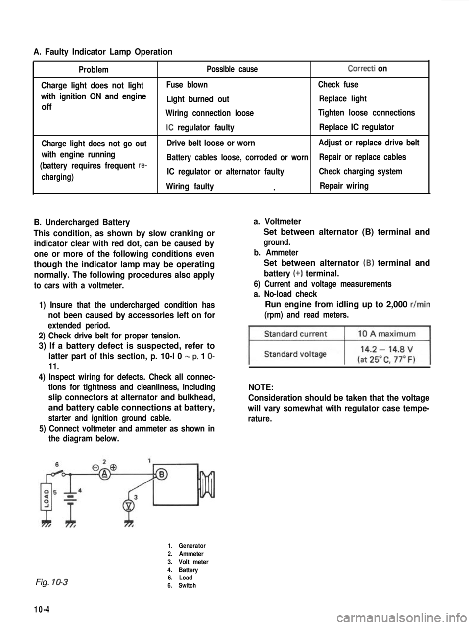
A. Faulty Indicator Lamp Operation
Problem
Charge light does not light
with ignition ON and engine
off
Charge light does not go out
with engine running
(battery requires frequent
re-
charging) Possible cause
Correcti on
Fuse blown
Check fuse
Light burned outReplace light
Wiring connection loose Tighten loose connections
IC regulator faultyReplace IC regulator
Drive belt loose or worn Adjust or replace drive belt
Battery cables loose, corroded or worn Repair or replace cables
IC regulator or alternator faultyCheck charging system
Wiring faulty.Repair wiring
B. Undercharged Battery a. Voltmeter
This condition, as shown by slow cranking or indicator clear with red dot, can be caused by
one or more of the following conditions even
though the indicator lamp may be operating
normally. The following procedures also apply
to cars with a voltmeter.
1) Insure that the undercharged condition has
not been caused by accessories left on for
extended period.
2) Check drive belt for proper tension.
3) If a battery defect is suspected, refer to
latter part of this section, p. 10-l 0 - p, 1 O-
11.
4) Inspect wiring for defects. Check all connec- tions for tightness and cleanliness, including
slip connectors at alternator and bulkhead,
and battery cable connections at battery,
starter and ignition ground cable.
5) Connect voltmeter and ammeter as shown inthe diagram below.
Set between alternator (B) terminal and
ground.
b. Ammeter
Set between alternator (B) terminal and
battery (+) terminal.
6) Current and voltage measurements
a. No-load check
Run engine from idling up to 2,000 r/min
(rpm) and read meters.
NOTE:
Consideration should be taken that the voltage
will vary somewhat with regulator case tempe-
rature.
Fig. 10-3
10-4
1.Generator
2.Ammeter
3. Volt meter
4. Battery
6. Load
6. Switch
Page 244 of 962
![SUZUKI GRAND VITARA 1987 Service Repair Manual [Carrier and hold-down]
The battery carrier and hold-down clamp should
be clean and free from corrosion before instal-
ling the battery. The carrier should be in good
condition so that it will support SUZUKI GRAND VITARA 1987 Service Repair Manual [Carrier and hold-down]
The battery carrier and hold-down clamp should
be clean and free from corrosion before instal-
ling the battery. The carrier should be in good
condition so that it will support](/manual-img/20/57437/w960_57437-243.png)
[Carrier and hold-down]
The battery carrier and hold-down clamp should
be clean and free from corrosion before instal-
ling the battery. The carrier should be in good
condition so that it will support the battery
securely and keep it level.
Make certain there are no parts in carrier before
installing the battery.
To prevent the battery from shaking in its
carrier, the hold-down bolts should be tight but
not over tightened.
[Visual inspection]
Check for obvious damage, such as cracked or
broken case or cover, that could permit loss of
electrolyte. If obvious damage is noted, replace
the battery. Determine cause of damage and
correct as needed.
Check the battery terminal and cords for corro-
sion. If any, it should be cleaned.
[Built-in indicator]
This sealed battery has a built-in temperature
compensated indicator in the top of the battery.
This indicator is to be used with the following
diagnostic procedure. When observing the
indicator, make sure that the battery has a clean
top. A light may be needed in some poorly-lit
areas.
Under normal operation, two indications can
be seen
2
Clear
RedCHARGING
NECESSARY
Fig. lo-23
l Clear with Red Dot
This means the discharging battery. In this case,
charge the battery until the indicator will be
blue with red dot. The charging and electrical
systems should also be checked at this time. If
any defective is found, correct it. While charging
it, if the battery feels hot 52°C (125” F), or if
violent gassing or spewing of electrolyte through
the vent hole occurs, discontinue charging or
reduce charging rate.
[Jump starting in case of emergency with
auxiliary (booster) battery]
NOTE:
l Do not push or tow the vehicle to start.
Damage to the emission system and/or to
other parts of the vehicle may result.
8 Both booster and discharged battery should
be treated carefully when using jumper cables.
Follow the procedure outlined below, being
careful not to cause sparks:
CAUTION:
l Departure from these conditions or the
procedure below could result in: (1)
Serious personal injury (particularly to
eyes) or property damage from such
causes as battery explosion, battery acid,
or electrical burns; and/or (2) damage to
electronic components of either vehicle.
l Never expose battery to open flame or
electric spark-batteries generate a gas
which is flammable and explosive.
l Remove rings,watches,and other
jewelry. Wear approved eye protection.
l Do not allow battery fluid to contact
eyes, skin, fabrics, or painted surfaces -
fluid is a corrosive acid. Flush any con-
tacted area with water immediately and
thoroughly. Be careful that metal tools
or jumper cables do not contact the
positive battery terminal (or metal in
contact with it) and any other metal on
the car, because a short circuit could
occur. Batteries should always be kept
out of the reach of children.
1) Set parking brake and place transmission in
neutral. Turn off the ignition, turn off lights
and all other electrical loads.
2) Check electrolyte level. If level is below low
level line, replace battery.
NOTE:
When jump starting an engine with charging
equipment, be sure equipment used is 12volt
and negative ground. Do not use 24volt charging
equipment. Using each equipment can cause
serious damage to the electrical system or
electronic parts.
10-11